
Related Manuals for Regulus CSE TC W iPWM MFB


Summary of Contents for Regulus CSE TC W iPWM MFB
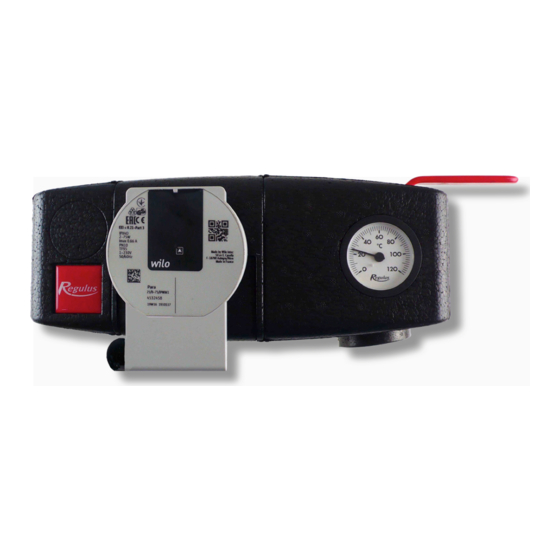
- Page 1 Installation and Operation Manual CSE TC W iPWM MFB PUMP STATION CSE TC W iPWM MFB...
- Page 2 1. Introduction CSE TC W iPWM MFB pump station is designed to be installed on the return pipe to the heat pump, where it ensures circulation through the heat pump circuit. The circulation pump is switched by an external controller, the pump speed controlled by PWM signal. With no PWM signal the pump runs at max.
-
Page 3: Flow Direction
3. Flow direction FLOW DIRECTION SMĚR PROUDĚNÍ 4. Wilo-Para iPWM1 Pump 4.1. General Information The Wilo Para 25/8 iPWM1 is a wet running circulation pump. The pump speed is controlled by the PWM signal. When the PWM signal is disconnected, the pump runs at its maximum speed. - Page 4 4.2. Permitted and Prohibited Pump Positions 4.3. Pump Wiring The pump must be wired / disconnected by a qualified person in compliance with EN 50110-1! Wilo PARA 25/8 iPWM1 pump wiring 1.POWER SUPPLY (1 ~ 230V, 50 Hz) 2.CONTROL (iPWM) PWM in (brown) L (brown) PWM GND (blue)
-
Page 5: Technical Data
4.4. Technical Data Wilo PARA 25/8 iPWM1 Electric Data Electric Data 230 V, 50 Hz Power input (min./max.) 2 / 75 W Current (min./max.) 0.03 / 0.66 A Max. speed 4800 pm Speed control frequency converter Energy Efficiency Index ≤ 0,21 by EN 16 297/3 IP rating IPX4D Motor protection... - Page 6 4.6. Performace curves for Wilo Para 25/8 iPWM1 pump │...
-
Page 7: Maintenance And Cleaning
5. Ball Valve w. filter & magnet 5.1. Maintenance and cleaning 1. Close the ball valve by turning the lever clockwise by 90° (Fig. 1). 2. Unscrew the lid with magnet manually and take out the strainer (Fig. 2, 3). 3. - Page 8 ©2020 We reserve the right to errors, changes and improvements without prior notice. REGULUS spol. s r.o. E-mail: sales@regulus.eu Web: www.regulus.eu...
Need help?
Do you have a question about the CSE TC W iPWM MFB and is the answer not in the manual?
Questions and answers