
Related Manuals for Regulus CSE OTS MFB+ZV G


Summary of Contents for Regulus CSE OTS MFB+ZV G
- Page 1 Installation and Operation Manual CSE OTS MFB+ZV G PUMP STATION CSE OTS MFB+ZV G...
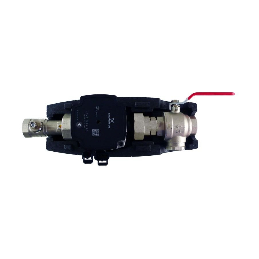
- Page 2 1. Introduction CSE OTS MFB+ZV G Pump Station is designed for installation on a heating system flow pipe. The pump station contains two ball valves, one ball valve is fitted with an integrated filter and magnet. The filter can be easily removed and cleaned without any tools. The pump station is intended for installation directly on a pipe, the minimum pipe centre distance from wall is 100mm.
- Page 3 3. Direction of Flow through the Pump Station SMĚR PROUDĚNÍ FLOW DIRECTION │...
- Page 4 4. UPM3 FLEX AS 25-75 130 mm Pump Design Wet-running circulation pump with G 6/4“ M threaded connections. Electric Data Power supply 230 V, 50 Hz Power input (min./max.) 2/52 W Current (min./max.) 0.04/0.50 A IP rating IP44 Max. speed 5766 rpm Weighted average power ≤...
- Page 5 Performance Display DISPLAY STATE PERFORMANCE in % of P STANDBY MODE 1 flashing green LED (EXTERNAL CONTROL ONLY) 1 green + 1 yellow LED LOW PERFORMANCE 0-25 1 green + 2 yellow LEDs MEDIUM-LOW PERFORMANCE 25-50 1 green + 3 yellow LEDs MEDIUM-HIGH PERFORMANCE 50-75 1 green + 4 yellow LEDs...
- Page 6 Prohibited pump positions Permissible pump (actuator) positions Pump Wiring N (blue) L (brown) PE (yellow-green) PWM GDN (blue) PWM out (black) PWM in (brown) power supply (A) and socket for power supply (A) signal (B) connectors and signal transmission (B) │...
- Page 7 5. Ball Valve with Filter & Magnet 5.1. Maintenance, Cleaning 1. Close the ball valve by turning the lever by 90° in the direction of the OFF arrow (Fig. 1). 2. Unscrew the lid with magnet manually and take out the strainer (Fig. 2, 3). 3.
- Page 8 ©2020 We reserve the right to errors, changes and improvements without prior notice. REGULUS spol. s r.o. E-mail: sales@regulus.eu Web: www.regulus.eu...
Need help?
Do you have a question about the CSE OTS MFB+ZV G and is the answer not in the manual?
Questions and answers