Table of Contents
Advertisement
Quick Links
Advertisement
Table of Contents

Subscribe to Our Youtube Channel
Related Manuals for Atlas EVBL3310


Summary of Contents for Atlas EVBL3310
- Page 1 1 / 25 REV. 01 2023...
- Page 2 PRINTING CHARACTERS AND SYMBOLS Throughout this manual, the following symbols and printing characters are used to facilitate reading: Indicates the operations which need proper care Indicates prohibition Indicates a possibility of danger for the operators BOLD Important information TYPE WARNING: before operating the lift and carrying out any adjustment, read carefully chapter 7 “installation”...
-
Page 3: Table Of Contents
CONTENTS GENERAL INFORMATION PRODUCT IDENTIFICATION PACKING, TRANSPORT AND STORAGE PRODUCT DESCRIPTION TECHNICAL SPECIFICATION SAFETY INSTALLATION OPERATION AND USE MAINTENANCE TROUBLESHOOTING 3 / 25 REV. 01 2023... -
Page 4: General Information
CHAPTER 1 – GENERAL INFORMATION This chapter contains warning instructions to operate the lift properly and prevent injury to operators or objects. This manual has been written to be used by shop technicians in charge of the lift (operator) and routine maintenance technician (maintenance operator). - Page 5 CAUTIONS FOR THE SAFETY OF THE OPERATOR Operators must not be under the influence of sedatives, drugs or alcohol when operating the machine. Before operating the lift, operators must be familiar with the position and function of all controls, as well as with the machine features shown in the chapter “Operation and use”...
-
Page 6: Product Identification
CHAPTER 2 – PRODUCT IDENTIFICATION The identification data of the machine are shown in the label placed on the control unit. LOGO ………. Type: ………. Model: ………. Serial Number: ………. Year of manufacturing: ………. Capacity: ………. Voltage: ………. Power: Use the above data both to order spare parts and when getting in touch with the manufacturer (inquiry). -
Page 7: Packing, Transport And Storage
CHAPTER 3 - PACKING, TRANSPORT AND STORAGE PACKING The packing of the lift is delivered in following components: ➢ N. 1 Lift packed in steel frame ➢ N. 1 Accessories packed in a carton box (If requested, optional accessories are available to satisfy each customer’s requirements). The average weight of the package is 1,590 lbs. -
Page 8: Product Description
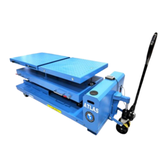
CHAPTER 4 - PRODUCT DESCRIPTION LIFT DESCRIPTION (Ref. Figure 1) The lift has been designed for the lifting of battery or engine of electric vehicles for maintenance. The maximum lifting weight is as specified on the serial plate. All mechanical frames, such as platforms, base frames and arms have been built in steel plate to make the frame stiff and strong while keeping a low weight. -
Page 9: Technical Specification
CHAPTER 5 - TECHNICAL SPECIFICATION SIZE AND MAIN FEATURES (Ref. Figure 2) CAPACITY 3,310 lbs (1500KG) Max. lifting height 71 in (1810mm) Min. lift height 29 in (738mm) Length of the platform 68-79.75 in (1728 - 2026mm) Width of platform 32 in (810mm) Tilting angle in left/right side +/- 5.1°... - Page 10 Figure 2 - LAYOUT 10 / 25 REV. 01 2023...
- Page 11 HYDRUALIC POWER UNIT The following hydraulic power unit (Fig.3) can be found by removing the mobile jack (Fig.1-10) and the cover (Fig.1-7). Oil tank Oil dipstick Lowering solenoid valve Motor Pressure Valve block overload valve Fig.3 Use wear proof oil for hydraulic drive, in conformity with ISO 6743/4 rules (HM class). The oil with features similar to those shown in the table is recommended.
- Page 12 Figure 4 – HYDRAULIC PLAN Oil filter Non return valve Gear pump Lowering solenoid valve Motor Speed control valve Pressure overload valve Hydraulic cylinders 12 / 25 REV. 01 2023...
- Page 13 Figure 5a – ELECTRICAL WIRING DIAGRAM (400V/380V-3PH) Power switch KA1/KA3 Relay Breaker KA2/KA4 Relay Motor 1.5KW Lifting button M2/M3 Linear actuator Lowering button Thermal relay Not available for this model Switch power Tilting forward button Contactor AC Tilting backward button Lowering solenoid valve Tilting leftward button Beeper...
- Page 14 Figure 5b – ELECTRICAL WIRING DIAGRAM (230V/220V-1PH) Power switch KA1/KA3 Relay Breaker KA2/KA4 Relay Motor 1.5KW Lifting button M2/M3 Linear actuator Lowering button Thermal relay Not available for this model Switch power Tilting forward button Contactor AC Tilting backward button Lowering solenoid valve Tilting leftward button Beeper...
-
Page 15: Safety
CHAPTER 6 – SAFETY Read this chapter carefully and completely because it contains important information for the safety of the operator and the person in charge of maintenance. The lift has been designed and built for lifting vehicles and making them stand above level in a closed area. - Page 16 PERSONNEL CRUSHING RISKS During lowering the lift, personnel must not be within the area covered by the lowering trajectory. The operator must be sure no one is in danger before operating the lift. Fig. 7a Fig. 7c Fig. 7b BUMPING RISK When the lift is stopped at relatively low height for working, the risk of bumping against projecting parts occurs.
- Page 17 RISKS RESULTING FROM IMPROPER LIGHTING Make sure all areas next to the lift are well and uniformly lit, according to local regulations. 6.10 RISKS OF BREAKING COMPONENT DURING OPERATION Materials and procedures, suitable for the designed parameters of the lift, have been used by the manufacturer to build a safe and reliable product.
-
Page 18: Installation
CHAPTER 7 – INSTALLATION Only skilled technicians, appointed by the manufacturer, or by authorized dealers, must be allowed to carry out installation. Serious damage to people and to the lift can be caused if installations are made by unskilled personnel. CHECKING FOR PLACE SUITABILITY The lift has been designed to be used in covered and sheltered places free of overhead obstructions. - Page 19 MAKE THE ELECTRICAL HOOKUP TO HYDRAULIC POWER UNIT The hookup work must be carried out by a qualified electrician. Make sure that the power supply is right. Make sure the connection of the phases is right. Improper electrical hook-up can damage motor and will not be covered under warranty.
- Page 20 INSTALLATION OF MOBILE JACK • Use the supplied M8X30 screws and D.8 washers to fix the main jack (Fig.15-1) to the support welded on the base frame according to Fig.15. • Install the jack handle (Fig.15-2) on the main jack by the supplied shaft and cotter pin. Fig.15 7.8 CHECKS LESS LOAD During this procedure, observe all operating components and check for proper...
-
Page 21: Operation And Use
CHAPTER 8 - OPERATION AND USE Never operate the lift with any person or equipment below. Never exceed the rate lifting capacity. Do not permit the electric control unit to get wet! CONTROLS CONTROL PANEL (Figure 16) Controls for operating the lift are: POWER SWITCH (1) The switch can be set in two positions: ➢... - Page 22 SPEED UP BUTTON (7): NOT AVAILABLE FOR THIS MACHINE TILTING FORWARD BUTTON (8) ➢ When pressed, the top table is tilted forward. TILTING BACKWARD BUTTON (9) ➢ When pressed, the top table is tilted backward. TILTING LEFTWARD BUTTON (10) ➢ When pressed, the top table is tilted leftward. TILTING RIGHTWARD BUTTON (10) ➢...
- Page 23 TO MOVE THE LIFT • Make sure to lower the lift completely before moving the lift. • Check to be sure the mobile jack is connected to the lift tightly; • Before moving, check to make sure to provide an accessible exit. •...
-
Page 24: Maintenance
CHAPTER 9 - MAINTENANCE Only trained personnel who knows how the lift works, must be allowed to service the lift. To service properly the lift, the following has to be carried out: • use only genuine spare parts as well as equipment suitable for the work required; •... -
Page 25: Troubleshooting
CHAPTER 10 – TROUBLESHOOTING A list of possible troubles and solutions is given below ROUBLE OSSIBLE AUSE OLUTION The main switch is not turned on Turn the switch on There is no power Check Power on to restore if necessary The lift does not work The electrical wires are Reconnect...
Need help?
Do you have a question about the EVBL3310 and is the answer not in the manual?
Questions and answers