Table of Contents
Advertisement
Advertisement
Table of Contents

Subscribe to Our Youtube Channel
Related Manuals for Atlas OH-10X


Summary of Contents for Atlas OH-10X
- Page 1 Model: OHX10000X Revised: 05/26/2021...
-
Page 2: Table Of Contents
CONTENTS Product Features and Specifications ..........3 Installation Requirement .............4 Steps of Installation ..............6 Exploded View ................22 Test Run ...................30 Operation Instruction ..............32 Maintenance ................33 Trouble Shooting ...............34 Lift Disposal ..................34 Warranty ...................35... -
Page 3: Product Features And Specifications
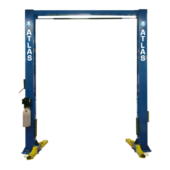
I. PRODUCT FEATURES AND SPECIFICATIONS CLEARFLOOR DIRECT-DRIVE MODEL FEATURES MODEL OHX10000X (See Fig.1) · Direct-drive design minimizes the lift wear parts and breakdown ratio. · Dual hydraulic cylinders, designed and made to high standards, with high quality seals. · Self-lubricating UHMW Polyethylene sliders and bronze bushings. ·... -
Page 4: Installation Requirement
II. INSTALLATION REQUIREMENT A. TOOLS REQUIRED ✓ Rotary Hammer Drill (Φ19) Carpenter’s Chalk ✓ ✓ Hammer Screw Sets ✓ ✓ Level Bar Tape Measure (7.5m) ✓ ✓ English Spanner (12") Pliers ✓ ✓ Ratchet Spanner With Socket (28 Socket Head Wrench (3 ✓... - Page 5 B. Equipment storage and installation requirements. The equipment should be stored or installed in a shady, normal temperature, ventilated and dry place. B. The equipment should be unloaded and transferred by forklift. Fig.4 D. SPECIFICATIONS OF CONCRETE (See Fig. 10) Concrete must adhere to the specifications listed below, failure to do so may result in lift and/or vehicle falling.
-
Page 6: Steps Of Installation
III. STEPS OF INSTALLATION A. Location of Installation Check and ensure the installation location (concrete, layout, space size etc.) is suitable for lift installation. B. Use a carpenter’s chalk line to establish installation layout of columns (See Fig. 6). Fig. 6 Chalk Line 144 3/8”... - Page 7 3. Loosen the screws of the upper package stand, take off the upper column and remove the package stand. 4. Move aside the parts and check the parts according to the shipment parts list (See Fig. 9,10). Fig. 9 Fig. 10 Parts in the shipment parts list Parts in the parts box (37) 5.Open the bag of parts and check the parts of the parts bag according to parts bag...
- Page 8 D. Position power side column Lay columns parallel at installation site, position the power-side column according to the actual installation site. It is suggested to install the power-side column on the front-right side from which vehicles are driven onto the lift however the power-side column can be on either side.
- Page 9 F. Position columns Place the columns on the installation layout of base plate. Install the anchor bolts. Do not tighten the anchor bolts (See Fig.14) Width between columns:118 1/8” Fig.14 Note: Minimum embedment of anchors is 4”. Drilling Cleaning Bolting Fig.
- Page 10 G. Install the top beam on the lift. (Fig.16) Fig. 16...
- Page 11 H. Check the vertical plumbness of the columns with a level and adjust with the shims if the columns are not vertical. Tighten the anchor bolts (See Fig.17) Measure the vertical of column from front and side by a lever bar or not.
- Page 12 Install the limit switch control bar and limit switch (See Fig. 18). Use 3# Socket Head Wrench to loosen the Screw of drive rod for adjustment Connect the blue wire to terminal #11 on limit switch and terminal A1 on AC contactor of power unit.
- Page 13 J. Install safety cable (See Fig. 19) 2. Pass the other end of the cable up from the 1. Pass one end of the cable through the bottom of the other lift bottom of the carriage. carriage. Cable through the bottom of the carriage Cables pass through the top plate of the carriages After installation...
- Page 14 . Install cables (See Fig. 20). Fig. 20...
- Page 15 L. Install oil hoses and tighten all the oil hose connections, using thread tape where possible (See Fig. 21) Fig. 21...
- Page 16 Install power unit and connect oil hose (See Fig. 22) The hose goes through the clamp After installing the fitting in the power unit, tighten the nut with 19 Wrench 用 19 梅开扳手锁紧螺母 Fig. 22...
- Page 17 N. Install safety cable (See Fig. 23) Pass through safety cable View B View A Fig. 23...
- Page 18 O. Install lifting arms and adjust the arm locks 1. Install the lifting arms (See Fig. 24). 2. Lower the carriages to the lowest position, then use the wrench to loosen the nut of gear (See Fig. 25). 3. Adjust the arm lock as direction of arrow (See Fig.
- Page 19 Q. Install electrical system Connect the power source according to the requirements on the power unit. Note: 1. For operator safety the power unit must be properly grounded. Single phase motor ( See Fig. 28). 1. Connecting the two power supply lines ( L and Wire N) to terminals of AC Active...
- Page 20 Motor Wire Fig. 29 Remove this wire before Fig. 30 connecting the Limit Switch Three phase motor 1. Circuit diagram (See Fig. 31) Push button Limit switch Fig. 31...
- Page 21 2. Connection step (See Fig. 32) a. The source wires (L1, L2, L3) connected with terminals of AC contactor marked L1, L2, L3 respectively. b. Terminals 4# of control button connected with wire 12# (brown wire) of limit switch; wire 11# (blue wire) connected with A1 terminals of AC contactor, Earth wire (yellow and green wire) of limit switch is connected with terminal earth wire of the motor.
-
Page 22: Exploded View
IV. EXPLODED VIEW Model 210CX Fig. 33... - Page 23 PARTS LIST FOR MODEL 210CX Item Part# Description Qty. 11209206 Power side Column 81513001 Power Unit 10209003 Hex Bolt 10209004 Rubber Ring 10209005 MS Self-locking Nut 11206002 Safety block Pin 10209007 Safety Spring 10209008 Safety Cover 10209009 Cup Head Bolt M6*8 10209010 φ10 Snap Ring 10620059...
- Page 24 Item Part# Description Qty. 10201002 Hex Bolt M8*16 10209039 φ10 Lock Washer 11217114A Rubber Pad Assy. 10420138 M6*16 Socket bolt 10209134 Rubber Pad 11680030B Rubber Pad Support Frame 10206025A Foam Cushion for control bar 10201005 Split pin 11206025C Connecting Pin for Control Bar 11202011 Control Bar 11206042...
- Page 25 4.1 Lifting arm assy. (10203156) exploded view Fig.34 Part no Name 10206048 Hex nut 10209039 washer 10209022 washer 11206049 Moon gear 11203146 Outer arm 11203147 Middle arm 10201149 Cup head bolt 11203148 Inner arm...
- Page 26 (10209014-01) exploded view 4.5 Cylinders Fig. 35 Part list for cylinder Part no Name 17-1 10209069 O-ring 17-2 10209070 Bleeding Plug 17-3 10209071 Support Ring 17-4 10209072 Y-ring 17-5 10209073 O-ring 17-6 11209074 Piston 17-7 10209075 O-Ring 17-8 11217076 Piston rod 17-9 11209077 Piston Rod Fitting...
- Page 27 POWER UNIT 220V/60HZ/1Phase Fig. 36...
- Page 28 PARTS LIST FOR MANUAL POWER UNIT Parts for Manual Power Unit, 220V/60Hz/1 phase Item Part# Description Qty. Note 81400180 Rubber pad 81400130 Starting capacitor 81400088 Running capacitor 10420148 Screw with washer 81400066 Capacitor cover 81400363 Motor connector 80101013 Manifold block 10209149 Washer 81400276...
-
Page 29: Test Run
Illustration of hydraulic valve for hydraulic power unit Release valve Oil return port Relief valve Oil output port Release valve handle throttle valve Check valve Fig 48 V. TEST RUN 1. Adjustment of synchronous cables (See Fig. 49) Use wrench to hold the cable end, meanwhile using ratchet spanner tighten the cable nut until the two cables are in the same tension. - Page 30 3. Bleeding air from oil cylinder (See Fig. 50) This hydraulic system is designed to bleed air by loosening Bleeding Plug the bleeding screw. Lift the carriages to about 12 inches and loosen the bleeding plug on the cylinder. Then lower the lift until fluid comes out.
-
Page 31: Operation Instruction
Fig. 52 Hydraulic System VI. OPERATION INSTRUCTIONS Please read the safety tips carefully before operating the lift To lift vehicle 1. Keep work site near the lift clean and clear at all times; 2. Position carriages and lift arms to the lowest position; 3. -
Page 32: Maintenance
3. Open the arms and position them to the shortest length; 4. Drive away the vehicle. Note: In order to extend the service life of the cylinder and seals, raise the machine to top at least once a day VII. MAINTENANCE SCHEDULE Monthly: 1. -
Page 33: Trouble Shooting
VIII.TROUBLE SHOOTING TROUBLE CAUSE REMEDY 1. Button does not work 1. Replace button 2. Wiring connections are not in good 2.Repair all wiring connections Motor does not condition 3. Motor burned out 3. Repair or replace motor 4. Height Limit Switch is damaged 4.Replace the Limit Switch 5. -
Page 34: Warranty
X. WARRANTY: This item is warranted for five (5) years on structural components, two (2) years on hydraulic cylinders, and one (1) year on electric or air / hydraulic power units from invoice date. Wear items are covered by a 90 day warranty.
Need help?
Do you have a question about the OH-10X and is the answer not in the manual?
Questions and answers