Advertisement
Quick Links
50
Q
YEARS
ISO 9001
1969-2019
Certified Quality
EN-61010-1
Security
4/20 m A
0/10 V dc
Process
Process
±20 m A
±10 V dc
Process
Process
1. Installation and start-up
1. Read how to operate the instrument (see section 9)
2. Install the instrument at the panel
• consider to move the panel installation to the last step if your panel prevents access to
the rear configuration keys.
3. Connect the power supply to power-up the instrument (see section 5)
• for a list of display errors see section 11
4. Connect the input signal to the instrument (see section 5)
5. Configure the input signal (see section 10)
• default configuration is 4/20 mA=0/100 %
• if you need as different reading, operate span and offset configurations to adjust the read-
ing to your needs.
6. Modify the offset (see section 9) if needed
7. Modify the span (see section 9) if needed
Access the user's manual (see section 3) for detailed explanations. Do not
forget to read the 'installation precautions' section at the user's manual.
When the marks 'Attention' or 'Risk of electrical shock' appear, read
the documentation for information about the nature of the risk.
2. Material included
The instrument is provided with the following elements :
• 1 x instrument EBR
• 1x plug-in screw terminals, connected to the instrument (for input signal and power)
• 2x metal side fixations for panel mount
• 1 x quick installation guide
3. Additional documentation
User's manual EBR
www.fema.es/docs/5495_EBR_manual_en.pdf
Datasheet EBR
www.fema.es/docs/5497_EBR_datasheet_en.pdf
Quick installation guide EBR
www.fema.es/docs/5499_EBR_installation_en.pdf
CE Declaration of conformity
www.fema.es/docs/5250_CE-Declaration_MBR_en.pdf
Warranty
www.fema.es/docs/4153_Warranty1_en.pdf
Web
www.fema.es/Series_BAR
Scan the QR code to directly
access the user's manual of
this instrument.
FEMA
· MANUFACTURING FOR INDUSTRIAL AUTOMATION
EBR · QUICK INSTALLATION GUIDE
5
4. How to order
YEARS
Extended Warranty
Reference
Description
EN-61326-1
EBR
Indicador de barra
Electromagnetic C.
EBR.1442
Indicador de barra con personalización
5. Connections
O+
Offset
O-
S+
S-
Span
Input
I+
I-
1 2 3
4 5
Table 1
|
INPUT SIGNAL CONNECTIONS
INPUT
Input terminals
signal
1
2
3
4/20 mA
mA+
mA -
0/10 Vdc
comm.
+ Vdc
±20 mA
± mA
comm.
±10 Vdc
comm.
± Vdc
6. Dimensions and panel cut-out 'mm' (in)
24 mm
(0.95 in.)
96 mm
15
(3.78 in.)
(0.60 in.)
power 0 Vdc
-
fuse
Power 24 V dc isolated, consumption <2 W
+
power +24 Vdc
Power fuse 200 m A time-lag
Vdc signal
common
mA signal
Table 2
|
POWER CONNECTIONS
POWER
Power terminals
4
5
24 Vdc ±10%
+ 24 Vdc
0 Vdc
(isolated)
7. How to panel the instrument
1.
Remove the two metal side fixations at the sides of the instrument.
2.
Insert the instrument, through the panel front, into the panel cut out.
3.
Place again the two metal side fixations, and screw them against the panel.
55 mm
8
(2.16 in.)
(0.31 in.)
Panel
cut-out
21.5 mm
(0.85 in.)
92.5 mm
(3.64 in.)
SERIES · BAR
Section SPECIAL . BAR METERS
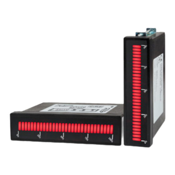
8. Front view
Table 3
|
FRONT VIEW
Bar graph
Percentage
Table 4
|
HORIZONTAL AND VERTICAL MOUNTINGS
5499r00
www.fema.es
Advertisement

Related Manuals for Fema EBR Series


Summary of Contents for Fema EBR Series
- Page 1 6. Dimensions and panel cut-out ‘mm’ (in) 7. How to panel the instrument Remove the two metal side fixations at the sides of the instrument. User’s manual EBR www.fema.es/docs/5495_EBR_manual_en.pdf 24 mm Insert the instrument, through the panel front, into the panel cut out. (0.95 in.) Datasheet EBR www.fema.es/docs/5497_EBR_datasheet_en.pdf...
- Page 2 1 second, the display is powered off for 1 second, and the displays restarts with the new 4 mA 20 mA Input legislation. Free of cost warranty extension of 5 years, avail- configuration active. able at (see section 3). FEMA · MANUFACTURING FOR INDUSTRIAL AUTOMATION www.fema.es...
Need help?
Do you have a question about the EBR Series and is the answer not in the manual?
Questions and answers