
Related Manuals for H3C WSG1812X-PWR


Summary of Contents for H3C WSG1812X-PWR
- Page 1 H3C WSG1812X-PWR Wireless Integrated Services Gateway Installation Guide New H3C Technologies Co., Ltd. http://www.h3c.com Document version: 5W104-20231205...
- Page 2 The information in this document is subject to change without notice. All contents in this document, including statements, information, and recommendations, are believed to be accurate, but they are presented without warranty of any kind, express or implied. H3C shall not be liable for technical or editorial errors or omissions contained herein.
- Page 3 Preface This installation guide describes the installation procedures for the WSG1812X-PWR wireless integrated services gateway, including preparing for installation, installing the wireless integrated services gateway, and accessing the wireless integrated services gateway. This preface includes the following topics about the documentation: •...
- Page 4 It is normal that the port numbers, sample output, screenshots, and other information in the examples differ from what you have on your device. Documentation feedback You can e-mail your comments about product documentation to info@h3c.com. Your comments or suggestions would be highly appreciated.
-
Page 5: Table Of Contents
Contents 1 Preparing for installation ············································································· 1 Safety recommendations ··································································································································· 1 Safety symbols ··········································································································································· 1 General safety recommendations ·············································································································· 1 Electrical safety ·········································································································································· 1 Laser safety ················································································································································ 2 Examining the installation site ···························································································································· 2 Temperature and humidity ························································································································· 2 Cleanliness ················································································································································· 2 Cooling ·······················································································································································... -
Page 6: Preparing For Installation
Preparing for installation Safety recommendations To avoid any equipment damage or bodily injury, read the following safety recommendations before installation. Note that the recommendations do not cover every possible hazardous condition. Safety symbols When reading this document, note the following symbols: WARNING means an alert that calls attention to important information that if not understood or followed can result in personal injury. -
Page 7: Laser Safety
Laser safety WARNING! Do not stare into any open apertures of operating transceiver modules or optical fiber connectors. The laser light emitted from these apertures might hurt your eyes. CAUTION: • Before you remove the optical fiber connector from a fiber port, execute the shutdown command in interface view to shut down the port. -
Page 8: Cooling
Substance Concentration limit (particles/m Dust particle diameter ≥ 5 µm To eliminate corrosion and premature aging of components, the equipment room must also meet limits on salts, acids, and sulfides, as shown in Table1-3. Table1-3 Harmful gas limits in an equipment room Max. -
Page 9: Emi
• Before working with the device, wear ESD gloves and ESD garment, and remove conductive objects such as jewelry or watch. Make sure the wrist strap makes good skin contact and is reliably grounded. • Always remember to wear an ESD wrist strap when working with a transceiver module. No ESD wrist strap is provided with the device. -
Page 10: Lightning Protection
• Keep the device far away from radio transmitting stations, radar stations, and high-frequency devices. • Use electromagnetic shielding, for example, shielded interface cables, when necessary. • To prevent signal ports from getting damaged by overvoltage or overcurrent caused by lightning strikes, route interface cables only indoors. -
Page 11: Pre-Installation Checklist
Figure1-4 Installation tools Pre-installation checklist Table1-4 Pre-installation checklist Item Requirements Result • There is a minimum clearance of 100 mm (3.94 in)) around the device for heat dissipation. Ventilation • A good ventilation system is available at the installation site. Temperature 0°C to 45°C (32°F to 113°F) Humidity... - Page 12 Item Requirements Result • The front and rear of the rack are a minimum of 0.8 m (31.50 in) away from walls or other devices. • The device is far away from any moist area and heat source. Safety • precautions You have located the emergency power switch in the equipment room.
- Page 13 Contents 1 Installing the device ···················································································· 1 Confirming installation preparations ··················································································································· 1 Installation flowchart··········································································································································· 2 Mounting the device on a workbench ················································································································ 2 Installing the device in a 19-inch rack ················································································································ 3 Grounding the device ········································································································································· 5 (Optional) Installing network port lightning protectors ························································································ 7 (Optional) Installing a surge protected power strip·····························································································...
-
Page 14: Installing The Device
WARNING! Keep the tamper-proof seal on a mounting screw on the chassis cover intact, and if you want to open the chassis, contact H3C Support for permission. Otherwise, H3C shall not be liable for any consequence caused thereby. Confirming installation preparations Before you install the device, verify that you have read "Preparing for installation"... -
Page 15: Installation Flowchart
Installation flowchart Figure1-1 Installation flowchart Mounting the device on a workbench CAUTION: • Mount the device on a workbench in the equipment room. • Do not place heavy objects on the device. If a standard 19-inch rack is not available, you can mount the device on an anti-static workbench in the equipment room. -
Page 16: Installing The Device In A 19-Inch Rack
Place the device on the workbench with the upside up. Make sure the four rubber feet stand firmly on the workbench. Figure1-2 Mounting the device on a workbench Installing the device in a 19-inch rack IMPORTANT: • Mount the device in a 19-inch rack in the equipment room. •... - Page 17 Figure1-3 Installing cage nuts Unpack the M4 screws (packed with the mounting brackets), and then use the M4 screws to attach the mounting brackets to the device. Figure1-4 Attaching the mounting brackets to the device Supporting the device bottom with one hand and holding the device front with the other, push the device gently into the rack.
-
Page 18: Grounding The Device
Figure1-5 Attaching the mounting brackets to the front rack posts Grounding the device WARNING! • Correctly connecting the grounding cable is crucial to lightning protection and EMI protection. Before installing or using the device, connect the grounding cable for it correctly. •... - Page 19 Figure1-6 Grounding the device with a grounding strip Grounding the device through the rack If the device is installed in a rack, you can connect the other end of the grounding cable to the grounding point on the rack. Make sure the rack is grounded reliably. Figure1-7 Grounding the device through the rack...
-
Page 20: (Optional) Installing Network Port Lightning Protectors
Grounding the device with a grounding conductor buried in the earth If earth is available at the installation site, you can ground the device with a grounding conductor buried in the earth. Hammer a 0.5 m (1.64 ft) or longer angle iron or steel tube into the earth to serve as a grounding conductor. -
Page 21: (Optional) Installing A Surge Protected Power Strip
Examine the port LED to verify that the port is operating correctly. Figure1-9 Installing a lightning protector for a network port (Optional) Installing a surge protected power strip CAUTION: If you use an AC power line routed from outdoors for the device, use a surge protected power strip for the device to protect against damages caused by lightning strikes. -
Page 22: Connecting Ethernet Cables
Connecting Ethernet cables Connecting an Ethernet copper port Connect one end of the Ethernet cable to the Ethernet copper port on the device, and the other end to the Ethernet port on the peer device. After powering on the device, examine the LEDs of the fixed Ethernet copper port. For more information about the LED description, see "Appendix B LEDs."... -
Page 23: Connecting The Power Cord
Figure1-10 Connecting an optical fiber Connecting the power cord WARNING! To avoid bodily injury, first connect the power cord to the device, and then connect the power cord to the power source in the equipment room. CAUTION: Before connecting the power cord, make sure the device is grounded correctly. To connect the power cord: Connect one end of the AC power cord to the AC-input power receptacle on the device. -
Page 24: Verifying The Installation
System is starting... Press Ctrl+T to xmodem download... Press Ctrl+D to access BASIC-BOOTWARE MENU... Booting Normal Extended BootWare The Extended BootWare is self-decompressing..Done **************************************************************************** H3C WSG1812X-PWR BootWare, Version 1.00 **************************************************************************** Compiled Date : Jun 6 2022 Memory Type : DDR4 SDRAM... - Page 25 Cryptographic algorithms tests passed. Line con0 is available. Press ENTER to get started. Press Enter at the prompt, and you can configure the device when the prompt <H3C> appears. During the startup process, the CPLD is automatically upgraded to the latest version.
- Page 26 Contents Log in to the device ························································································ 1 Log in through Telnet or SSH····························································································································· 1 Configure Telnet login ································································································································ 1 Configure SSH login ··································································································································· 1 Log in through the console port·························································································································· 1 About this task ············································································································································ 1 Prerequisites ·············································································································································· 1 Configure terminal parameters ···················································································································...
- Page 27 Log in to the device You can log in to a device through Telnet, SSH, or the Console port, or from the Web interface. • Telnet/SSH login—Log in to the device through a remote connection to configure or manage the device. •...
- Page 28 • When you disconnect a PC from the device, first remove the RJ-45 connector and then remove the DB-9 connector as a best practice. • If the PC does not have an RS-232 interface but has an USB port, use a USB-to-RS-232 adapter to connect the console cable.
- Page 29 Procedure To log in to the device from the Web interface through a wired connection: Visit the default IP address 192.168.0.100 to access the local Web interface. Enter the default username and password, and then click the login button. For security purposes, change the login password as prompted.
- Page 30 WSGContents 1 Hardware management and maintenance ·················································· 1 Displaying hardware information about the device ···························································································· 1 Displaying software and hardware version information about the device ·················································· 1 Displaying the operational statistics about the device················································································ 1 Displaying information about the device ···································································································· 2 Displaying electrical label information for the device ·················································································...
-
Page 31: Hardware Management And Maintenance
<H3C> display version H3C Comware Software, Version 7.1.064, Alpha 5611 Copyright (c) 2004-2022 New H3C Technologies Co., Ltd. All rights reserved. H3C WSG1812X-PWR uptime is 0 weeks, 0 days, 0 hours, 3 minutes Last reboot reason : Power on Boot image: flash:/boot.bin Boot image version: 7.1.064, Alpha 5611... -
Page 32: Displaying Information About The Device
===============display version=============== H3C Comware Software, Version 7.1.064, Alpha 5611 Copyright (c) 2004-2022 New H3C Technologies Co., Ltd. All rights reserved. H3C WSG1812X-PWR uptime is 0 weeks, 0 days, 0 hours, 12 minutes Last reboot reason : Power on Boot image: flash:/boot.bin Boot image version: 7.1.064, Alpha 5611... -
Page 33: Displaying Electrical Label Information For The Device
An electrical label is a profile of a device. It contains the permanent configuration, including the serial number, manufacturing date, MAC address, and vendor name. Use the command to display the electrical label information for the display device manuinfo device. <H3C> display device manuinfo DEVICE_NAME:WSG1812X-PWR DEVICE_SERIAL_NUMBER:DPPMWWB123456 MAC_ADDRESS:000f-e212-6103 MANUFACTURING_DATE:2006-08-08 VENDOR_NAME:H3C... -
Page 34: Displaying The Memory Usage Of The Device
CPU usage at the interval of 5 minutes). Displaying the memory usage of the device Use the command to display the memory usage statistics for the device. display memory <H3C> display memory Memory statistics are measured in KB: Slot 1: Total Used... -
Page 35: Restrictions And Guidelines
Before you reboot the device, perform the following tasks: Use the command to save the running configuration. For more information about the save command, see configuration file management commands in H3C WSG1812X-PWR save Wireless Integrated Services Gateway Fundamentals Command Reference. Use the commands to verify that you... - Page 36 Contents 1 Troubleshooting ·························································································· 1 Power supply failure ··········································································································································· 1 Symptom ···················································································································································· 1 Solution ······················································································································································ 1 No display or garbled display on the configuration terminal ·············································································· 1 Symptom ···················································································································································· 1 Solution ······················································································································································ 1 Software loading failure······································································································································ 2 Symptom ···················································································································································· 2 Solution ······················································································································································...
- Page 37 Troubleshooting Power supply failure Symptom The device cannot be powered on. The system status LED (SYS) is off. Solution To resolve the issue: Verify that the power source is as required. Verify that the power cord is connected securely. Verify that the power cord is in good condition. If the issue persists, contact Technical Support.
- Page 38 Software loading failure Symptom The device fails in software loading. Solution To resolve the issue: Verify that the physical ports are connected securely and correctly. If a port is not connected securely, reconnect the port and make sure the connections are correct. View the software loading process displayed on the HyperTerminal to check for errors.
- Page 39 Contents 1 Appendix A Chassis views and technical specifications ····························· 1 Chassis views ···················································································································································· 1 Technical specifications ····································································································································· 1...
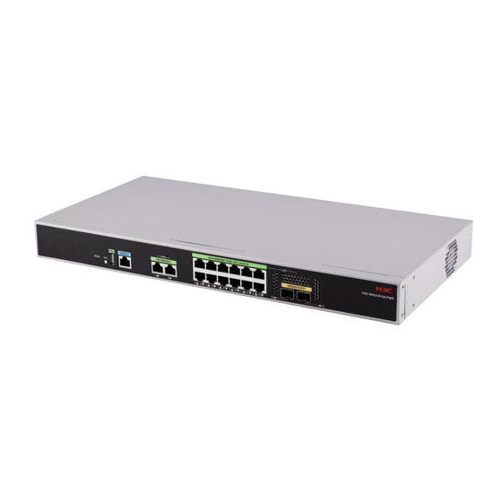
- Page 40 Appendix A Chassis views and technical specifications Chassis views Figure1-1 Front view (1) Reset button (RESET) (2) USB port (4) 100/1000BASE-T autosensing Ethernet ports (3) Console port WAN 1 and WAN 2 (5) 100/1000BASE-T-PoE+ autosensing Ethernet ports LAN 3 to LAN 14 (6) 10GBASE-R-SFP+ ports Figure1-2 Rear view (1) Grounding screw...
- Page 41 Item Specification than 15 ms. Memory 2GB DDR4 Storage media 4GB eMMC memory Dimensions (H × W × D) (excluding the 43.6 × 440 × 220 mm (1.72 × 17.32 × 8.66 in) rubber feet and mounting brackets) AC power supply Rated voltage range: 100 to 240 VAC @ 50/60 Hz System power consumption 11.8W to 173 W (including 150W PoE output)
- Page 42 Contents 1 Appendix B LEDs ······················································································· 1 LEDs ·································································································································································· 1 LED description ·················································································································································· 1...
- Page 43 Appendix B LEDs LEDs Figure1-1 LEDs (1) System status LED (SYS) (2) 100/1000MBASE-T autosensing port LEDs (3) 100/1000BASE-T-PoE+ autosensing port LEDs (4) 10GBASE-R-SFP+ port LED (5) 10GBASE-R-SFP+ port LED LED description Table1-1 LED description Mark Status Description Flashing green (4 The system is starting up.
- Page 44 Contents 1 Appendix C Optional transceiver modules ·············································· 1-1 Views······························································································································································· 1-1 Specifications ·················································································································································· 1-1...
- Page 45 A transceiver module that has "MM" in its name supports multi-mode optical fibers. A transceiver module that has "SM" in its name supports single-mode optical fibers. The H3C transceiver modules are subject to change over time. For the most recent list of H3C transceiver modules, contact Technical Support or marketing staff.
- Page 46 Item SFP-GE-SX-MM850-A Max transmission distance 550 m (1804.46 ft) Data rate 1250 Mb/s Connector type Duplex LC connector Fiber mode 50 μm Fiber diameter Output power –9.5 to 0 dBm ≤ –17 dBm Receiver sensitivity ≤ –3 dBm Light saturation Table1-2 SFP-GE-LX-SM1310-A specifications Item SFP-GE-LX-SM1310-A...
- Page 47 Item SFP-XG-SX-MM850-E Data rate 10.31 Gb/s Connector type Duplex LC connector Fiber mode 50 μm Fiber diameter Output power –7.3 to –1 dBm ≤ –9.9 dBm Receiver sensitivity ≤ 0.5 dBm Light saturation...
Need help?
Do you have a question about the WSG1812X-PWR and is the answer not in the manual?
Questions and answers