
Subscribe to Our Youtube Channel
Related Manuals for Beckhoff C6640-0020


Summary of Contents for Beckhoff C6640-0020
- Page 1 Installation and Operating instructions for Control Cabinet Industrial PC C6640/ C6650 up to -0030 Version: 1.6 Date: 2018-01-24...
-
Page 3: Table Of Contents
Mains Socket Power supply cords Power Supply Connection with 24 V power supply unit (optional) Beckhoff power supply technology Electrical Data Pin assignment of the connectors Pin assignment power supply Pin assignment external wiring Fitting the Cables... - Page 4 Disposal UPS Software Components (optional) Installation on the PC Help files Troubleshooting Fault correction Beckhoff Support and Service Beckhoff branches and partner companies Beckhoff company headquarters Beckhoff Support Beckhoff Service Assembly dimensions C6640, Configuration with 100-240 V Power Supply C6640, Configuration with 24 V...
-
Page 5: Foreword
Beckhoff Automation GmbH & Co.KG. Delivery conditions In addition, the general delivery conditions of the company Beckhoff Automation GmbH & Co.KG apply. C6640, C6650... -
Page 6: Description Of Safety Symbols
Foreword Description of safety symbols The following safety symbols are used in this operating manual. They are intended to alert the reader to the associated safety instructions. Acute risk of injury!! If you do not adhere the safety advise adjoining this symbol, there is DANGER immediate danger to life and health of individuals! Risk of injury! -
Page 7: Basic Safety Measures
Foreword Basic safety measures Only switch the PC off after Before the Industrial PC is switched off, software that is running must closing the software be properly closed. Otherwise it is possible that data on the hard disk is lost. Please read the section on Switching the Industrial PC on and off. -
Page 8: Operator's Obligation To Exercise Diligence
Foreword Operator's obligation to exercise diligence The operator must ensure that • the Industrial PC is only used for its intended use (see also Product Description). • the Industrial PC is in a sound condition and in working order during operation (see also chapter Servicing). •... -
Page 9: Product Description
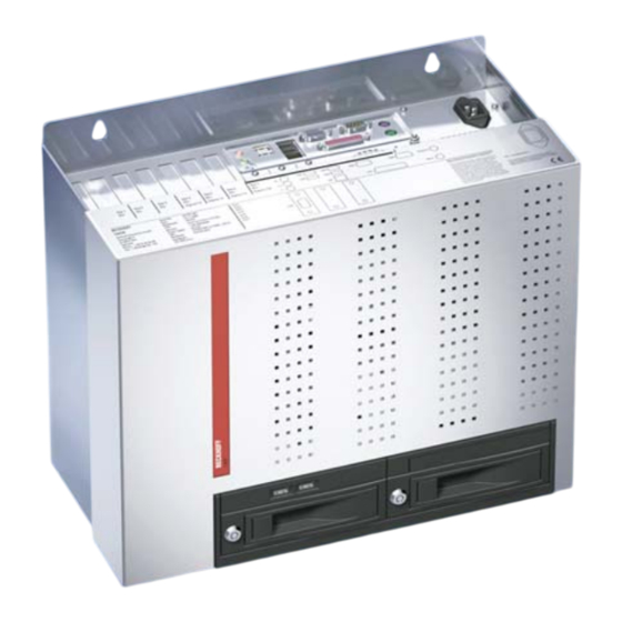
Product Description Product Description Appropriate Use The C6640 and C6650 Industrial PCs are designed for mounting in control cabinets for machine and plant engineering applications. Opening the Housing View of the C6650, configuration with 100-240 V power supply unlock key (1) The housing cover is locked by a latch. - Page 10 Product Description Taking off the housing cover slides on both sides (2) Now the housing cover can be taken off completely, so providing access to the components. The reassembly of the cover takes place in reverse order. Ensure that the cover engages into the slides (2).
-
Page 11: Ac Full Range Power Supply
Product Description Configuration with 100-240 V Full Range Power Supply View of the C6650 with 100-240 V full range power supply. Removing the card holder card holder knurled screw After loosening the knurled screw the card holder can be lifted off (see arrow). -
Page 12: Interfaces Up To C6640/ C6650-0020
Product Description Interfaces up to C6640/ C6650-0020 ATX motherboard X103 X114 X110 X108 interfaces X107 X105 X111 X109 X115 X104 X113 X112 X106 X116 PS/2 connections PS/2 A PC keyboard can be connected to the upper PS/2 connector (X103), while the lower PS/2 connector (X104) allows a PS/2 mouse to be used. Serial interface RS 232 The basic version of the Industrial PC has one serial interface COM1,... -
Page 13: Interfaces C6640/ C6650-0030
Product Description Interfaces C6640/ C6650-0030 ATX motherboard X116 X105 interfaces X104 X117 X115 X112 X113 X103 X118 X109 X111 X114 X119 X108 X110 PS/2 connections PS/2 The upper PS/2 connector (X104) allows a PS/2 mouse to be used, while a PC keyboard can be connected to the lower PS/2 connector (X103). -
Page 14: Installation Instructions
4. Please keep the associated paperwork. It contains important information for handling the unit. 5. Check the contents for visible shipping damage. 6. If you notice any shipping damage or inconsistencies between the contents and your order, you should notify Beckhoff Service. C6640, C6650... -
Page 15: Installation Of The Pc In The Control Cabinet
Installation Instructions Installation of the PC in the control cabinet The C6640 and C6650 Industrial PCs are designed for mounting in control cabinets for machine and plant engineering applications. The ambient conditions specified for operation must be observed (see chapter Technical data). -
Page 16: Power Supply Connection With 100-240
Installation Instructions Power Supply Connection with 100-240 V power supply unit Supplied mains power unit The Industrial PC is serially fitted with a 100-240 V , 50-60 Hz full range power supply unit . Current carrying capacity of Output voltages from the Current loading 100-240 V power supply unit maximum... -
Page 17: Beckhoff Power Supply Technology
However, over time this reduces the service life of the battery. The new Beckhoff power supply technology approach addresses this problem and now offers the user the option of switching the PC off without the need for using the battery, thereby reducing the load on the battery. -
Page 18: Electrical Data
Installation Instructions signal lamp connection or via a contactor. With this solution the main switch generally only has to be switched off if the control cabinet has to be opened. The battery will only be used in the event of a power failure. In order to maintain a screen display for the Industrial PC in the event of a power failure, the power supply unit is equipped with a UPS output 27 V / 1.4 A for connecting a Control Panel with a display dimension up to 19... -
Page 19: Pin Assignment Power Supply
Installation Instructions Pin assignment power supply Pin assignment for X101 Function connecting the power Power Supply supply and the battery pack (optional) Battery Pack (with USV) Pin assignment external wiring Pin assignment for X102 Function connecting PC-ON, Power- UPS-Output Status und UPS-Output Power-Status PC-ON power supply +pole... -
Page 20: Fitting The Cables
Installation Instructions Fitting the Cables Wiring in accordance with Fit the cables for the power supply of the Industrial PC, the connection of wiring diagram the battery pack as well as the connection of the power-switch in accordance with the wiring diagram, using the included material for assembling the connectors. -
Page 21: Connecting 24V
Installation Instructions Connecting 24V Power Supply The external wiring consists of the connection of the power supply, the battery pack (optional) and the connection of customized components for shutting down the PC. Cable Cross Sections Note cable cross sections, For the connection of the power supply, wiring with a cable-cross-section avoid voltage drop! of 1.5 mm must be used. -
Page 22: Wiring Diagram
Installation Instructions Wiring diagram Wiring according to the wiring diagram (the circuit of PC_ON and Power- Status is symbolical): Wiring diagram power supply and external switch Connection of the Battery Pack and UPS Output Connection of the Battery Pack and UPS Output only in combination with Note integrated UPS (order option). -
Page 23: Connecting Devices
Installation Instructions Connecting devices Power supply plug The power supply plug must be withdrawn! Attention Please read the documentation for the external devices prior to connecting them. During thunderstorms, plug connector must neither be inserted nor removed. When disconnecting a plug connector, always handle it at the plug. Do not pull the cable! Connecting cables The connections are located at the top of the Industrial PC and are... -
Page 24: Operating Instructions
Operating Instructions Operating Instructions Please also refer to chapter Foreword. Switching the Industrial PC on and off Switch on • The Industrial PC C6640 is switched on via the main switch beside the mains socket (see chapter Power Supply Connection with 24 VDC power supply unit). -
Page 25: Servicing And Maintenance
Operating Instructions Servicing and Maintenance Please also refer to chapter Foreword. Cleaning the Industrial PC Disconnect from power supply Switch off the Industrial PC and all connected devices, and disconnect the Industrial PC from the power supply. Attention The Industrial PC can be cleaned with a soft, damp cloth. Do not use any aggressive cleaning materials, thinners, scouring material or hard objects that could cause scratches. -
Page 26: Emergency Procedures
The driver software comes with a detailed help function. System The help files can be called up either directly from the configuration register by clicking the Help button, or under via Start > Programs > Beckhoff > UPS software components. C6640, C6650... -
Page 27: Troubleshooting
Nothing happens after the Industrial No power supply to the Industrial Check power supply cable PC has been switched on Other cause Call Beckhoff Service The Industrial PC does not boot Setup settings are incorrect Check the setup settings fully... -
Page 28: Beckhoff Support And Service
Please contact your Beckhoff branch office or partner company for local support and service on Beckhoff products! The contact addresses for your country can be found in the list of Beckhoff branches and partner companies: www.beckhoff.com You will also find further documentation for Beckhoff components there. -
Page 29: Assembly Dimensions
Assembly dimensions Assembly dimensions The following pages show diagrams of the Industrial PC, with dimensions in mm. C6640, Configuration with 100-240 V Power Supply Assembly orientation The assembly of the unit must take place with the orientation diagrammed here. Attention C6640, C6650... -
Page 30: C6640, Configuration With 24 V Dc -Power Supply (Optional)
Assembly dimensions C6640, Configuration with 24 V -Power Supply (optional) Assembly orientation The assembly of the unit must take place with the orientation diagrammed here. Attention C6640, C6650... -
Page 31: Ac Power Supply
Assembly dimensions C6650, Configuration with 100-240 V Power Supply Assembly orientation The assembly of the unit must take place with the orientation diagrammed here. Attention C6640, C6650... -
Page 32: Dc -Power Supply (Optional)
Assembly dimensions C6650, Configuration with 24 V -Power Supply (optional) Assembly orientation The assembly of the unit must take place with the orientation diagrammed here. Attention C6640, C6650... -
Page 33: Appendix
Appendix Appendix Technical data Industrial PC Dimensions (W x H x D): see chapter Assembly dimensions C6640, C6650 Weight: C6640: 11 kg (basic configuration) C6650: 12 kg (basic configuration) Do not use the PC in areas The Industrial PC may not be used in areas of explosive hazard. of explosive hazard The following conditions must be observed during operation: Environmental conditions...
Need help?
Do you have a question about the C6640-0020 and is the answer not in the manual?
Questions and answers