Table of Contents
Advertisement
Quick Links
Advertisement
Chapters
Table of Contents

Related Manuals for Beckhoff C6675


Summary of Contents for Beckhoff C6675
- Page 1 Manual | EN C6675 Industrial PC 2024-03-27 | Version: 1.4...
-
Page 3: Table Of Contents
Grounding of the industrial PC .................. 23 4.3.2 Connecting cables and power supply ................ 25 Switching the industrial PC on and off .................... 26 5 Beckhoff Device Manager ........................ 28 6 Decommissioning ........................... 30 Disconnecting the power supply and cables ................... 30 Disassembly and disposal....................... 31 7 Maintenance ............................ 32... - Page 4 Table of contents 10.2 Approvals ............................ 48 Version: 1.4 C6675...
-
Page 5: Notes On The Documentation
EP1590927, EP1789857, EP1456722, EP2137893, DE102015105702 and similar applications and registrations in several other countries. ® EtherCAT is registered trademark and patented technology, licensed by Beckhoff Automation GmbH, Germany Copyright © Beckhoff Automation GmbH & Co. KG, Germany. The distribution and reproduction of this document as well as the use and communication of its contents without express authorization are prohibited. -
Page 6: For Your Safety
Exclusion of liability Beckhoff shall not be liable in the event of non-compliance with this documentation and thus the use of the devices outside the documented operating conditions. -
Page 7: Fundamental Safety Instructions
• the operating instructions are in good condition and complete, and always available for reference at the location where the products are used. C6675 Version: 1.4... -
Page 8: Notes On Information Security
For your safety Notes on information security The products of Beckhoff Automation GmbH & Co. KG (Beckhoff), insofar as they can be accessed online, are equipped with security functions that support the secure operation of plants, systems, machines and networks. Despite the security functions, the creation, implementation and constant updating of a holistic security concept for the operation are necessary to protect the respective plant, system, machine and networks against cyber threats. -
Page 9: Product Overview
Product overview Product overview The industrial PC C6675 belongs to the series of powerful industrial PCs for control cabinet installation with ATX motherboard. The device is suitable for various applications and requirements. Thanks to the available processors, the industrial PC can be used for the following applications, among others: •... -
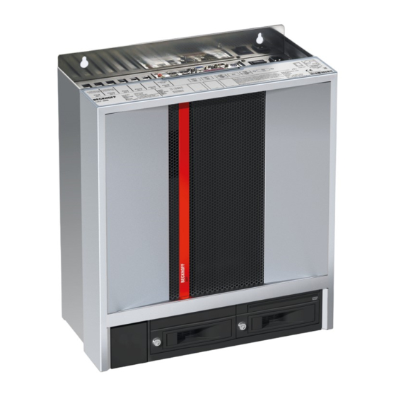
Page 10: Structure
Product overview Structure Fig. 1: Structure Table 1: Key - C6675 structure Component Description Mounting concept Holes for mounting the industrial PC in the control cabinet Connection compartment Access to interfaces of the industrial PC Name plate Information on the equipment of the industrial PC... -
Page 11: Interface Description
The power supply is connected via the IEC socket (X101) on the top of the industrial PC. The assignment includes a protective conductor (1), a neutral conductor (2) and an outer conductor (2) (see Fig. 3). X101 Fig. 3: Voltage socket 100-240 V C6675 Version: 1.4... -
Page 12: Fig. 4 Ps/2 Mouse And Keyboard
Mouse Data Reserved Ground (S)VCC 5 V supply voltage MCLK Mouse Clock Reserved Table 4: PS/2 interface keyboard pin assignment Name Description KDAT Keyboard data MDAT Mouse Data Ground (S)VCC 5 V supply voltage KCLK Keyboard Clock MCLK Mouse Clock Version: 1.4 C6675... -
Page 13: Usb
USB interfaces. The following table shows the interface assignment based on the device generation: Table 5: USB interfaces based on device generation Device generation USB interfaces C6675-0060 4x USB 3.0 C6675-0070 4x USB 3.2 Gen. 2 Each of the four interfaces supplies 900 mA current and is electronically protected. -
Page 14: Ethernet Rj45
The controllers are used as follows, based on the device generation: Table 7: Controller classification based on device generation Generation Controller ® C6675-0060 Intel i219 for LAN1 and i210 for LAN2 C6675-0070 If you use the Ethernet ports with EtherCAT or for Real-Time Ethernet applications, you have to regard the... -
Page 15: Dvi
BIOS setup if required. X116 Fig. 8: RS232 interface pin numbering Table 10: RS232 pin assignment Signal Description Data Carrier Detect Receive Data Transmit Data Data Terminal Ready Ground Data Set Ready Request to Send Clear to Send Ring Indicator C6675 Version: 1.4... -
Page 16: Displayport
LVDS lane 2 + Ground LVDS lane 2 - LVDS lane 3 + Ground LVDS lane 3 - Config 1 Config 2 AUX channel + Ground AUX channel - Hot-plug detection Power supply: ground Power supply: 3.3 V / 500 mA Version: 1.4 C6675... -
Page 17: Audio Connections
The three sockets are brought out for 3.5 mm jack plugs. The pins of the jack plugs are assigned as follows: Fig. 11: Jack plug pin assignment Table 12: Jack plug pin assignment Connection Left sound signal Right sound signal Common ground (return) C6675 Version: 1.4... -
Page 18: Optional Interfaces
Slot bracket for a serial interface module C9900-E209, C9900-E210 or C9900-E211, can only be ordered together with module C9900-M569 Slot bracket for two serial interface modules C9900-E209, C9900-E210 or C9900-E211, can only be ordered together with module Version: 1.4 C6675... -
Page 19: Name Plate
9 10 11 12 Fig. 12: Name plate Table 16: Legend C6675 name plate Description Manufacturer, including address Serial number (BTN) Model: The last four digits indicate the device generation Date of manufacture... -
Page 20: Commissioning
3. Check your delivery for completeness by comparing it with your order. 4. Check the contents for visible shipping damage. 5. In case of discrepancies between the package contents and the order, or in case of transport damage, please inform Beckhoff Service (see Chapter 10.1 Service and Support). Version: 1.4 C6675... -
Page 21: Control Cabinet Installation
• Mount the device only in the orientations shown in the documents. The C6675 Industrial PC is designed for mounting in control cabinets in machine and plant engineering applications. Please observe the environmental conditions prescribed for the operation (see Chapter 9 Technical data [} 46]). -
Page 22: Fig. 14 Dimensions
1. Insert the fastening screws into the drill holes in the control cabinet. 2. Hang the PC on the screws at the marked points of the mounting concept (see Fig. 15). 3. Tighten the fastening screws. ð You have successfully installed the industrial PC in the control cabinet. Version: 1.4 C6675... -
Page 23: Connecting The Industrial Pc
10 mm for the ground connection. In the case of a round conductor, also use a cable lug with a ring and place the ring over the grounding bolt. C6675 Version: 1.4... -
Page 24: Fig. 16 Grounding Bolt For Functional Earthing
Commissioning Fig. 16: Grounding bolt for functional earthing Version: 1.4 C6675... -
Page 25: Connecting Cables And Power Supply
Proceed as follows to connect the 100-240 V power supply unit: 1. Check that the mains voltage is correct. 2. Plug the corresponding IEC power cable into the IEC socket of the industrial PC. 3. Connect the industrial PC to a Schuko socket. C6675 Version: 1.4... -
Page 26: Switching The Industrial Pc On And Off
You can then switch off the power supply. If you remove the 24 V from the PC-ON input before you have switched off the power supply, the operating system restarts. Therefore, 24 V must be applied to the input until you have switched off the power supply. Version: 1.4 C6675... - Page 27 You then use the installation package to install the UPS software components. The UPS software components come with a detailed help function. Call up the help files either directly from the configuration register by clicking the Help button or start the file under Start > Programs > Beckhoff > UPS software components.
-
Page 28: Beckhoff Device Manager
• User name: Administrator • Password: 1 You also have the option of using the Beckhoff Device Manager to remotely configure the industrial PC via a web browser. More detailed information is available in the Beckhoff Device Manager manual. First start Beckhoff Device Manager When your industrial PC is booted for the first time, the Beckhoff Device Manager also starts automatically for the first time. -
Page 29: Fig. 18 Beckhoff Device Manager - Start Page
Secure passwords Strong passwords are an important prerequisite for a secure system. Beckhoff supplies the device images with standard user names and standard passwords for the operating system. It is imperative that you change these. Controllers are shipped without a password in the UEFI/BIOS setup. Beckhoff recommends assigning a password here as well. -
Page 30: Decommissioning
To disconnect the cables from the industrial PC, proceed as follows: 1. Make a note of the wiring configuration, if you wish to restore it with another device. 2. Disconnect the data transmission cables from the industrial PC. 3. Finally, disconnect the grounding strap. Version: 1.4 C6675... -
Page 31: Disassembly And Disposal
• Electronic parts such as fans and circuit boards must be disposed of in accordance with national electronic scrap regulations. • Stick insulating tape over the poles of the CR2032 battery on the motherboard and dispose of the battery via the local battery recycling. C6675 Version: 1.4... -
Page 32: Maintenance
• Always keep the ventilation grilles free. • Only use a vacuum cleaner to clean the PC. The industrial PC does not have to be switched off for this. • Never use compressed air to clean the PC. Version: 1.4 C6675... -
Page 33: Table 17 Device Component Replacement Recommendations
NOTICE Use of incorrect spare parts The use of spare parts not ordered from Beckhoff Service can lead to unsafe and faulty operation. • Only use spare parts that you have ordered from Beckhoff Service. Beckhoff devices are manufactured from components of the highest quality and robustness. They are selected and tested for best interoperability, long-term availability and reliable function under the specified environmental conditions. - Page 34 • Only remove new electronic components from the ESD packaging (tinted plastic bag) after putting on the wrist grounding strap. • Do not walk around with electronic components in your hand if they are not in ESD packaging. Version: 1.4 C6675...
-
Page 35: Access To Device Components
3. Keep the card holder pressed onto the edge of the industrial PC while tightening the knurled screw again (section C). 4. For each plug-in card, press down the associated plastic element of the card holder until the plug-in card is firmly seated in its slot. ð You have mounted the card holder. C6675 Version: 1.4... -
Page 36: Fig. 21 Mounting Card Holder
2. Push the cover up as far as possible, inserting the hooks of the cover into the guides of the housing (2) (section B). 3. Place the cover into a straight position against the housing until the release handle snaps back into place (section C). ð You have mounted the cover on the housing. Version: 1.4 C6675... -
Page 37: Fig. 23 Mounting Housing Cover
Maintenance Fig. 23: Mounting housing cover C6675 Version: 1.4... -
Page 38: Replacing The Battery
Replace the battery with R/C (BBCV2), order number RC2032, nominal voltage 3 V. Using any other battery may cause fire or explosion. • Only replace the battery with a replacement battery from Beckhoff Service. • When replacing the battery, make sure that the polarity is correct. -
Page 39: Replacing The Storage Media
If you want to exchange a storage medium according to Beckhoff's recommendation, you must copy the data from the old to the new storage medium. You can use the Beckhoff Service Tool (BST) for this purpose. BST is a graphical backup and restore program for PCs with a Windows operating system. You can create an image of your operating system and use it to back up the operating system. -
Page 40: Fig. 25 Exchange Hard Disk
2. Pull the key of the hard drive caddy to unlock it (section B). 3. Open the hard drive caddy (section C). 4. Pull the SSD out of the hard drive caddy by the protruding Beckhoff sticker (section D). 5. Reinsert the new SSD in the same orientation. -
Page 41: Fig. 26 Exchange Ssd
Maintenance Fig. 26: Exchange SSD C6675 Version: 1.4... -
Page 42: Replacing The Fan
The device may be damaged if the wrong type of fan is installed. • Only replace the fans with replacement fans from Beckhoff Service. The fans ensure optimal cooling of the device. Order replacement fans only from Beckhoff. Please get in touch with your Beckhoff sales contact. -
Page 43: Fig. 28 Exchange Fan Top
Please contact Beckhoff Service for this. Exchange CPU cooler You can also replace the CPU cooler on the motherboard. Contact Beckhoff Service for a new cooler. To replace the CPU cooler, follow the steps below as shown in Figure 29: 1. -
Page 44: Fig. 29 Exchange Cpu Cooler
Maintenance Fig. 29: Exchange CPU cooler The old fan must be disposed of in accordance with the national electronic waste regulations. Version: 1.4 C6675... -
Page 45: Troubleshooting
Measures No function of the industrial PC Missing power supply of the Check the power supply cable industrial PC Call Beckhoff Service Other cause The industrial PC does not boot BIOS setup settings are incorrect Check BIOS setup settings (load... -
Page 46: Technical Data
Technical data Technical data Table 19: Technical data Product designation C6675 Dimensions (W x H x D) 410 x 480 x 201 mm Weight 15 kg basic configuration Supply voltage 100-240 V , 50-60 Hz, max. 5 A Power consumption Data sheet for calculating power consumption and power loss in the download finder - Data sheets: http://www.beckhoff.com/downloadfinder... -
Page 47: 10 Appendix
33415 Verl Germany Phone: + 49 5246/963-0 email: info@beckhoff.de The addresses of the worldwide Beckhoff branches and agencies can be found on our website at http:// www.beckhoff.com/. You will also find further documentation for Beckhoff components there. C6675 Version: 1.4... - Page 48 FCC approvals for Canada FCC: Canadian Notice This device does not exceed the class A limits for radiation, as specified by the Radio Interference Regulations of the Canadian Department of Communications. Version: 1.4 C6675...
- Page 49 Fig. 15 Control cabinet installation ......................Fig. 16 Grounding bolt for functional earthing ..................Fig. 17 Beckhoff Device Manager - Change passwords ................Fig. 18 Beckhoff Device Manager – Start page ..................Fig. 19 Positions of the fastening screws....................Fig. 20 Access device components......................
- Page 50 List of tables List of tables Table 1 Key - C6675 structure ........................Table 2 Current carrying capacity power supply unit ................Table 3 PS/2 interface mouse pin assignment..................Table 4 PS/2 interface keyboard pin assignment..................Table 5 USB interfaces based on device generation ................
- Page 52 More Information: Beckhoff Automation GmbH & Co. KG Hülshorstweg 20 33415 Verl Germany Phone: +49 5246 9630 info@beckhoff.com www.beckhoff.com...
Need help?
Do you have a question about the C6675 and is the answer not in the manual?
Questions and answers