Table of Contents
Advertisement
Quick Links
WAFER-IMX8MP SBC
WAFER-IMX8MP CPU Card
MODEL:
WAFER-IMX8MP
3.5" SBC with NXP i.MX 8M Plus Processor, 4GB LPDDR4,
16GB eMMC Flash, Dual Display via HDMI & MIPI DSI,
MIPI CSI, GPIO, Dual GbE, USB Type-C, RS-232/422/485,
Android 12 / Yocto 3.2 / Ubuntu 22.04, 0°C ~70°C and RoHS
User Manual
Page I
Rev. 1.00 - September 8, 2023
[MODEL NAME]
Advertisement
Table of Contents

Related Manuals for IEI Technology WAFER-IMX8MP Series


Summary of Contents for IEI Technology WAFER-IMX8MP Series
- Page 1 WAFER-IMX8MP SBC WAFER-IMX8MP CPU Card MODEL: WAFER-IMX8MP 3.5" SBC with NXP i.MX 8M Plus Processor, 4GB LPDDR4, 16GB eMMC Flash, Dual Display via HDMI & MIPI DSI, MIPI CSI, GPIO, Dual GbE, USB Type-C, RS-232/422/485, Android 12 / Yocto 3.2 / Ubuntu 22.04, 0°C ~70°C and RoHS User Manual Page I Rev.
- Page 2 WAFER-IMX8MP SBC Revision Date Version Changes September 8, 2023 1.00 Initial release Page II [MODEL NAME]...
- Page 3 WAFER-IMX8MP SBC Copyright COPYRIGHT NOTICE The information in this document is subject to change without prior notice in order to improve reliability, design and function and does not represent a commitment on the part of the manufacturer. In no event will the manufacturer be liable for direct, indirect, special, incidental, or consequential damages arising out of the use or inability to use the product or documentation, even if advised of the possibility of such damages.
- Page 4 WAFER-IMX8MP SBC Manual Conventions WARNING Warnings appear where overlooked details may cause damage to the equipment or result in personal injury. Warnings should be taken seriously. CAUTION Cautionary messages should be heeded to help reduce the chance of losing data or damaging the product. NOTE These messages inform the reader of essential but non-critical information.
-
Page 5: Table Of Contents
WAFER-IMX8MP SBC Table of Contents 1 INTRODUCTION ......................1 1.1 I ......................2 NTRODUCTION 1.2 M ....................3 ODEL ARIATIONS 1.3 F ........................3 EATURES 1.4 C ......................4 ONNECTORS 1.5 D ....................... 5 IMENSIONS 1.6 D ........................ 6 1.7 T .................. - Page 6 WAFER-IMX8MP SBC 3.2.11 Reset Button ....................27 3.2.12 Touch Connector .................... 28 3.2.13 USB Type-C Connector .................. 29 3.2.14 Wi-Fi/Bluetooth Module Slot ................. 30 3.3 E ......... 31 XTERNAL ERIPHERAL NTERFACE ONNECTOR ANEL 3.3.1 Audio Earphone Connector ................32 3.3.2 DC Power Input Connector ................32 3.3.3 HDMI Output Connector .................
- Page 7 WAFER-IMX8MP SBC List of Figures Figure 1-1: WAFER-IMX8MP ......................2 Figure 1-2: Connectors ........................4 Figure 1-3: Dimensions (mm) ......................5 Figure 1-4: Data Flow Diagram ...................... 6 Figure 3-1: Connector and Jumper Locations ................15 Figure 3-2: Debug Port Connector Location ................18 Figure 3-3: Download Key Location ...................
- Page 8 WAFER-IMX8MP SBC List of Tables Table 1-1: WAFER-IMX8MP Model Variations ................3 Table 1-2: Technical Specifications ....................8 Table 3-1: Peripheral Interface Connectors ................16 Table 3-2: Rear Panel Connectors ....................17 Table 3-3: Debug Port Connector Pinouts ................. 18 Table 3-4: GPIO Connector Pinouts ....................
-
Page 9: Introduction
WAFER-IMX8MP SBC Chapter Introduction Page 1... -
Page 10: Ntroduction
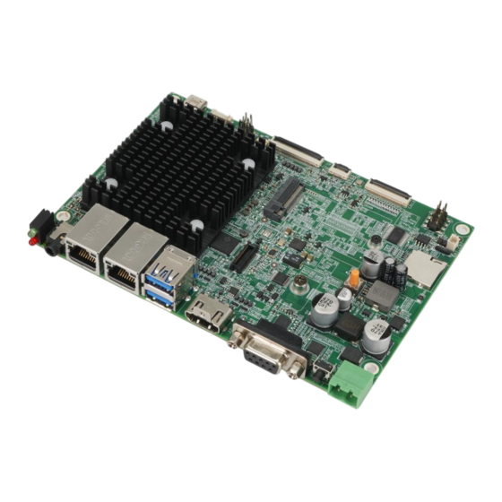
1.1 Introduction Figure 1-1: WAFER-IMX8MP The WAFER-IMX8MP series is a 3.5" form factor single bard computer. It has an on-board NXP i.MX 8M Plus which is an Arm® Cortex® -A53 quad-core processor with a Neural Processing Unit (NPU) operating at up to 2.3 TOPS. It is also pre-installed with 4 GB 3200 MHz LPDDR4 memory, and 16 GB eMMC NAND flash. -
Page 11: Model Variations
WAFER-IMX8MP SBC 1.2 Model Variations The model variations of the WAFER-IMX8MP series are listed below. Model No. Processor NXP i.MX 8M Plus Android 12 WAFER-IMX8MP-A/BD NXP i.MX 8M Plus Yocto 3.2 WAFER-IMX8MP-Y/BD NXP i.MX 8M Plus Ubuntu 22.04 WAFER-IMX8MP-U/BD Table 1-1: WAFER-IMX8MP Model Variations 1.3 Features... -
Page 12: Connectors
WAFER-IMX8MP SBC 1.4 Connectors The connectors on the WAFER-IMX8MP are shown in the figure below. Figure 1-2: Connectors Page 4... -
Page 13: Dimensions
WAFER-IMX8MP SBC 1.5 Dimensions The dimensions of the board are listed below: Figure 1-3: Dimensions (mm) Page 5... -
Page 14: Data Flow
WAFER-IMX8MP SBC 1.6 Data Flow Figure 1-4 shows the data flow between the system chipset, the CPU and other components installed on the motherboard. Figure 1-4: Data Flow Diagram Page 6... -
Page 15: Technical Specifications
WAFER-IMX8MP SBC 1.7 Technical Specifications WAFER-IMX8MP technical specifications are listed below. Specification WAFER-IMX8MP Processor NXP i.MX 8M Plus Quad (quad-core Cortex®-A53 up to 1.8 GHz) GC7000UL 3D (2 shaders), GC520L Up to 2.3 TOPS 4 GB LPDDR4-3200, up to 8GB Flash 16 GB eMMC NAND flash, up to 128GB 1 x microSD slot... -
Page 16: Table 1-2: Technical Specifications
WAFER-IMX8MP SBC Specification WAFER-IMX8MP Power Input 12 V DC Operating Temperature 0°C – 70°C (with air flow) Storage Temperature -20°C – 80°C Humidity 10% – 99%, non-condensing EMC & Safety EMC Class B Supported OS Android 12 / Yocto 3.2 (Linux Kernel 5.10) / Ubuntu 22.04 Table 1-2: Technical Specifications Page 8... -
Page 17: Unpacking
WAFER-IMX8MP SBC Chapter Unpacking Page 9... -
Page 18: Anti-Static Precautions
WAFER-IMX8MP SBC 2.1 Anti-static Precautions WARNING! Static electricity can destroy certain electronics. Make sure to follow the ESD precautions to prevent damage to the product, and injury to the user. Make sure to adhere to the following guidelines: Wear an anti-static wristband: Wearing an anti-static wristband can prevent electrostatic discharge. -
Page 19: Packing List
WAFER-IMX8MP SBC 2.3 Packing List NOTE: If any of the components listed in the checklist below are missing, do not proceed with the installation. Contact the IEI reseller or vendor the WAFER-IMX8MP was purchased from or contact an IEI sales representative directly by sending an email to sales@ieiworld.com. -
Page 20: Optional Items
WAFER-IMX8MP SBC 2.4 Optional Items The following are optional components which may be separately purchased: Item and Part Number Image 10.1" color TFT-LCD with projected capacitive touch (800x1280, 340 cd/m , LED, RoHS) (P/N : 23T00-01010AW01-RS) Camera module (2592x1944, 1/4", 8.5x14.5x5.45mm, sensor type: OV5640, RoHS) (P/N: 7I001-COD631A5SFE-RS) Speakers with cables (Speakers: 36.6x14x10.4mm, 8Ω,... - Page 21 WAFER-IMX8MP SBC Page 13...
-
Page 22: Connectors
WAFER-IMX8MP SBC Chapter Connectors Page 14... -
Page 23: Peripheral Interface Connectors
WAFER-IMX8MP SBC 3.1 Peripheral Interface Connectors This chapter details all the jumpers and connectors. 3.1.1 WAFER-IMX8MP Layout The figures below show all the connectors and jumpers. Figure 3-1: Connector and Jumper Locations Page 15... -
Page 24: Peripheral Interface Connectors
WAFER-IMX8MP SBC 3.1.2 Peripheral Interface Connectors The table below lists all the connectors on the board. Connector Type Label RTC battery connector 2-pin wafer BAT_CN1 Debug port connector 4-pin wafer CN16 Download key Onboard tact button GPIO connector 8-pin header LTE module slot M.2 B key 2242 microSD slot... -
Page 25: External Interface Panel Connectors
WAFER-IMX8MP SBC 3.1.3 External Interface Panel Connectors The table below lists the connectors on the external I/O panel. Connector Type Label Audio earphone jack Audio jack DC power input connector 2-pin terminal block CN26 HDMI output connector HDMI LAN connectors RJ-45 CN19, CN20 LED indicators... -
Page 26: Internal Peripheral Connectors
WAFER-IMX8MP SBC 3.2 Internal Peripheral Connectors The section describes all of the connectors on the WAFER-IMX8MP. 3.2.1 Debug Port Connector CN Label: CN16 CN Type: 4-pin wafer, p=1.25mm CN Location: See Figure 3-2 CN Pinouts: See Table 3-3 The connector is used to debug. Figure 3-2: Debug Port Connector Location Description DEBUG_TX... -
Page 27: Download Key
WAFER-IMX8MP SBC 3.2.2 Download Key CN Label: CN Type: On-board tact button CN Location: See Figure 3-3 The download key allows users to access the service mode for software update. Long-press the download key to boot the system into the service mode. Figure 3-3: Download Key Location 3.2.3 External GPIO Connector CN Label:... -
Page 28: Lte Module Slot
WAFER-IMX8MP SBC PIN NO. DESCRIPTION PIN NO. DESCRIPTION EXT_GPIO1 EXT_GPIO2 EXT_GPIO3 EXT_GPIO4 EXT_GPIO5 EXT_GPIO6 EXT_GPIO7 EXT_GPIO8 Table 3-4: GPIO Connector Pinouts 3.2.4 LTE Module Slot CN Label: CN Type: M.2 B-key 2242 slot CN Location: See Figure 3-5 See Table 3-5 CN Pinouts: The M.2 LTE module slot is keyed in the B position and accepts 2242 size of LTE modules. -
Page 29: Table 3-5: Lte Module Slot Pinouts
WAFER-IMX8MP SBC Description Description M2_DIS1 LTE_RXN LTE_UIM1_RESET LTE_RXP LTE_UIM1_CLK LTE_UIM1_DATA LTE_TXN LTE_UIM1_PWR LTE_TXP SIM2_SW PCIE_RXN LTE_UIM2_DATA PCIE_RXP LTE_UIM2_CLK LTE_UIM2_RESET PCIE_TXN LTE_UIM2_PWR PCIE_TXP PCIe_nCLKREQ_3V3 REF_CLKN PCIe_nWAKE_3V3 REF_CLKP SIM1_SW M2_PERST +3.3V +3.3V +3.3V Table 3-5: LTE Module Slot Pinouts Page 21... -
Page 30: Microsd Card Slot
WAFER-IMX8MP SBC 3.2.5 microSD Card Slot CN Label: CN Type: microSD slot CN Location: See Figure 3-6 The slot accepts microSD cards for data storage. Figure 3-6: MicroSD Card Location 3.2.6 MIPI DSI Output Connector CN Label: CN Type: 40-pin FPC, p=0.5 mm CN Location: See Figure 3-7 CN Pinouts:... -
Page 31: Table 3-6: Mipi Dsi Output Connector Pinouts
WAFER-IMX8MP SBC Description Description LCD_NC1 MIPI_D3P LCD_VDD LCD_VDD LCD_NC2 LCD_RESET LCD_NC3 LED_PWM MIPI_D0N LCD_NC4 MIPI_D0P LCD_NC5 MIPI_D1N LCD_LED- MIPI_D1P LCD_LED- LCD_NC6 MIPI_CKN LCD_NC7 MIPI_CKP LCD_VSN LCD_NC8 MIPI_D2N LCD_NC9 MIPI_D2P LCD_VSP LCD_LED+ MIPI_D3N LCD_LED+ Table 3-6: MIPI DSI Output Connector Pinouts Page 23... -
Page 32: Mipi Csi Connector
WAFER-IMX8MP SBC 3.2.7 MIPI CSI Connector CN Label: CN18 CN Type: 30-pin FPC, p=0.5 mm CN Location: See Figure 3-8 CN Pinouts: See Table 3-7 The MIPI CSI connector is used to connect to a camera module. Figure 3-8: MIPI CSI Connector Location Description Description CAM_LED-... -
Page 33: Sim Slot
WAFER-IMX8MP SBC 3.2.8 SIM Slot CN Label: U117 CN Type: Mini SIM slot, push-to-push CN Location: See Figure 3-9 CN Pinouts: See Table 3-8 The SIM card slot accepts a SIM card for LTE network communication. NOTE: A LTE module must be installed in the LTE module slot (J6) to provide WWAN communication. -
Page 34: Speaker Connector
WAFER-IMX8MP SBC 3.2.9 Speaker Connector CN Label: CN24 CN Type: 4-pin wafer CN Location: See Figure 3-10 CN Pinouts: See Table 3-9 This connector provides audio output to speakers. Figure 3-10: Speaker Connector Location Description SPK_LP SPK_LN SPK_RN SPK_RP Table 3-9: Speaker Connector Pinouts 3.2.10 RS-232/485 Serial Port Connector CN Label: CN Type:... -
Page 35: Reset Button
WAFER-IMX8MP SBC Figure 3-11: RS-232/485 Connector Location RS-232 RS-485 DATA- DATA+ Table 3-10: RS-232/485 Serial Port Connector Pinouts 3.2.11 Reset Button CN Label: CN Type: On-board tact button CN Location: See Figure 3-12 Use the reset button to reset the system. Figure 3-12: Reset Button Location Page 27... -
Page 36: Touch Connector
WAFER-IMX8MP SBC 3.2.12 Touch Connector CN Label: CN Type: 8-pin FPC, p=0.5 mm CN Location: See Figure 3-13 CN Pinouts: See Table 3-11 The touch connector is used to connect a touch panel. Figure 3-13: Touch Location Description TOUCH_VCC A_CPT_I2C_SCL A_CPT_I2C_SDA A_CPT_INT A_CPT_RST... -
Page 37: Usb Type-C Connector
WAFER-IMX8MP SBC 3.2.13 USB Type-C Connector CN Label: CN23 CN Type: USB Type-C CN Location: F igure 3-14 8 1 4 H CN Pinouts: Table 3-12 8 1 5 H The WAFER-IMX8MP has one USB Type-C port. The pinouts are shown below. Figure 3-14: USB Type-C Port Location Description Description... -
Page 38: Wi-Fi/Bluetooth Module Slot
WAFER-IMX8MP SBC 3.2.14 Wi-Fi/Bluetooth Module Slot CN Label: CN27 CN Type: 40-pin connector CN Location: F igure 3-15 7 9 1 H CN Pinouts: See Table 3-13 The slot supports Wi-Fi/Bluetooth modules. Figure 3-15: Wi-Fi/Bluetooth Module Slot Location Description Description BT_CTS WIFI_DATA0 BT_TXD... -
Page 39: External Peripheral Interface Connector Panel
WAFER-IMX8MP SBC Description Description WIFI_3V3 WIFI_INT_W WIFI_3V3 SD_RESET_W WIFI_3V3 WIFI_3V3 Table 3-13: Wi-Fi/Bluetooth Module Slot Pinouts 3.3 External Peripheral Interface Connector Panel Figure 3-16 shows the WAFER-IMX8MP external peripheral interface connector (EPIC) panel. The EPIC panel consists of the following: ... -
Page 40: Audio Earphone Connector
WAFER-IMX8MP SBC 3.3.1 Audio Earphone Connector CN Label: CN Type: Audio jack CN Location: See Figure 3-16 The audio earphone jack supports mic-in and line-out. Figure 3-17: Audio Earphone Connector 3.3.2 DC Power Input Connector CN Label: CN26 CN Type: 2-pin terminal block CN Location: See Figure 3-16... -
Page 41: Hdmi Output Connector
WAFER-IMX8MP SBC 3.3.3 HDMI Output Connector CN Label: CN Type: HDMI connector CN Location: See Figure 3-16 CN Pinouts: See Table 3-15 and Figure 3-19 The HDMI connectors can connect to HDMI devices. Description Description HDMI_DATA2 HDMI_DATA2# HDMI_DATA1 HDMI_DATA1# HDMI_DATA0 HDMI_DATA0# HDMI_CLK HDMI_ CLK#... -
Page 42: Lan Connectors
WAFER-IMX8MP SBC 3.3.4 LAN Connectors CN Label: CN19, CN20 CN Type: RJ-45 CN Location: F igure 3-16 8 0 8 H CN Pinouts: F igure 3-20 and Table 3-16 8 0 9 H The GbE LAN connector connects to a local network. Description Description MDIA0+... -
Page 43: Led Indicators
WAFER-IMX8MP SBC 3.3.5 LED Indicators CN Label: CN Type: CN Location: See Figure 3-16 The behaviors of the LED indicators are shown below. Status Description Green Power connected No power connected Turned on and boot into OS Not turned on / Failed to boot into OS Figure 3-21: LED Indicators Page 35... -
Page 44: Rs-232/422/485 Serial Port Connector
WAFER-IMX8MP SBC 3.3.6 RS-232/422/485 Serial Port Connector CN Label: CN25 CN Type: DB-9 connector CN Location: See Figure 3-16 CN Pinouts: See Table 3-18 and Figure 3-22 The pinouts for RS-232, RS-422 and RS-485 communication are shown below. The default mode is set to RS-232. Users can use software or app to configure the connector as RS-422 or RS-485. -
Page 45: Usb 5Gb/S Connectors
WAFER-IMX8MP SBC 3.3.7 USB 5Gb/s Connectors CN Label: CN21 CN Type: USB Type-A CN Location: F igure 3-16 8 1 4 H CN Pinouts: Table 3-19 and Figure 3-23 8 1 5 H The WAFER-IMX8MP has two external USB 5Gb/s ports. The USB connector can be connected to a USB 2.0 or USB 5Gb/s device. -
Page 46: Installation
WAFER-IMX8MP SBC Chapter Installation Page 38... -
Page 47: Anti-Static Precautions
WAFER-IMX8MP SBC 4.1 Anti-static Precautions WARNING: Failure to take ESD precautions during the installation of the WAFER-IMX8MP result permanent damage WAFER-IMX8MP and severe injury to the user. Electrostatic discharge (ESD) can cause serious damage to electronic components, including the WAFER-IMX8MP. Dry climates are especially susceptible to ESD. It is therefore critical that whenever the WAFER-IMX8MP or any other electrical component is handled, the following anti-static precautions are strictly adhered to. - Page 48 WAFER-IMX8MP SBC WARNING: The installation instructions described in this manual should be carefully followed in order to prevent damage to the WAFER-IMX8MP, WAFER-IMX8MP components and injury to the user. Before and during the installation please DO the following: Read the user manual: The user manual provides a complete description of the WAFER-IMX8MP installation instructions and configuration options.
-
Page 49: Module Installation
WAFER-IMX8MP SBC 4.3 M.2 Module Installation To install an M.2 module, please follow the steps below. Step 1: Locate the M.2 module slot. See Chapter 3. Step 2: Remove the retention screw secured on the motherboard. Step 3: Line up the notch on the module with the notch on the slot. Slide the M.2 module into the socket at an angle of about 20º... -
Page 50: Chassis Installation
WAFER-IMX8MP SBC 4.4 Chassis Installation 4.4.1 Airflow WARNING: Airflow is critical for keeping components within recommended operating temperatures. The chassis should have fans and vents as necessary to keep things cool. The WAFER-IMX8MP must be installed in a chassis with ventilation holes on the sides allowing airflow to travel through the heat sink surface. -
Page 51: Software Drivers
WAFER-IMX8MP SBC Chapter Software Drivers Page 43... -
Page 52: Available Drivers
WAFER-IMX8MP SBC 5.1 Available Drivers All the drivers for the WAFER-IMX8MP are available on IEI Resource Download Center (https://download.ieiworld.com). Type WAFER-IMX8MP and press Enter to find all the relevant software, utilities, and documentation. Figure 5-1: IEI Resource Download Center 5.2 Driver Download To download drivers from IEI Resource Download Center, follow the steps below. - Page 53 WAFER-IMX8MP SBC Step 3: Click the driver file name on the page and you will be prompted with the following window. You can download the entire ISO file ( ), or click the small arrow to find an individual driver and click the file name to download ( NOTE: To install software from the downloaded ISO image file in Windows 8, 8.1 or 10, double-click the ISO file to mount it as a virtual drive to view...
-
Page 54: A Regulatory Compliance
WAFER-IMX8MP SBC Appendix Regulatory Compliance Page 46... - Page 55 WAFER-IMX8MP SBC DECLARATION OF CONFORMITY This equipment has been tested and found to comply with specifications for CE marking. If the user modifies and/or installs other devices in the equipment, the CE conformity declaration may no longer apply. FCC WARNING This equipment complies with Part 15 of the FCC Rules.
-
Page 56: B Product Disposal
WAFER-IMX8MP SBC Appendix Product Disposal Page 48... - Page 57 WAFER-IMX8MP SBC CAUTION: Risk of explosion if battery is replaced by an incorrect type. Only certified engineers should replace the on-board battery. Dispose of used batteries according to instructions and local regulations. Outside the European Union–If you wish to dispose of used electrical and electronic products outside the European Union, please contact your local authority so as to comply with the correct disposal method.
-
Page 58: C Hazardous Materials Disclosure
WAFER-IMX8MP SBC Appendix Hazardous Materials Disclosure Page 50... -
Page 59: Rohs Ii Directive (2015/863/Eu)
WAFER-IMX8MP SBC C.1 RoHS II Directive (2015/863/EU) The details provided in this appendix are to ensure that the product is compliant with the RoHS II Directive (2015/863/EU). The table below acknowledges the presences of small quantities of certain substances in the product, and is applicable to RoHS II Directive (2015/863/EU). -
Page 60: China Rohs
WAFER-IMX8MP SBC C.2 China RoHS 此附件旨在确保本产品符合中国 RoHS 标准。以下表格标示此产品中某有毒物质的含量符 合中国 RoHS 标准规定的限量要求。 本产品上会附有”环境友好使用期限”的标签,此期限是估算这些物质”不会有泄漏或突变”的 年限。本产品可能包含有较短的环境友好使用期限的可替换元件,像是电池或灯管,这些 元件将会单独标示出来。 部件名称 有毒有害物质或元素 壳体 印刷电路板 金属螺帽 电缆组装 风扇组装 电力供应组装 电池 O: 表示该有毒有害物质在该部件所有物质材料中的含量均在 SJ/T11364-2014 與 GB/T26572-2011 标准规定的限量要求以下。 X: 表示该有毒有害物质至少在该部件的某一均质材料中的含量超出 SJ/T11364-2014 與 GB/T26572-2011 标准规定的限量要求。 Page 52...
Need help?
Do you have a question about the WAFER-IMX8MP Series and is the answer not in the manual?
Questions and answers