Table of Contents
Advertisement
Quick Links
Advertisement
Table of Contents

Related Manuals for LEMKEN Compact-Solitair 9 K H


Summary of Contents for LEMKEN Compact-Solitair 9 K H
- Page 1 Operating Instructions Seeding Combinations Compact-Solitair 9 K H - en - Item no. 175_4518 02/02.16 LEMKEN GmbH & Co. KG Weseler Straße 5, 46519 Alpen / Germany Telephone +49 28 02 81 0, Fax +49 28 02 81 220 lemken@lemken.com, www.LEMKEN.com...
- Page 3 However, this brief instruction is not a substitute for thorough study of the operating instructions. These operating instructions will help to familiarise you with the LEMKEN GmbH & Co. KG device and the options available for using it.
- Page 4 Remember that you should only use genuine LEMKEN spare parts. Reproduction parts have a negative influence on the function of the device, have a shorter ser- vice life and present risks and hazards that cannot be estimated by LEMKEN GmbH & Co. KG. They also increase the maintenance costs.
-
Page 5: Table Of Contents
CONTENTS General information ....................13 Liability ......................... 13 Guarantee ........................13 Copyright ........................14 Optional accessories ....................14 Notes ..........................14 Type plate ........................15 Symbols used in the Operating Instructions ............17 ... - Page 6 Operation on public highways ................... 32 3.7.1 Lighting system and identification ................32 3.7.2 Requirements of the tractor ..................32 3.7.3 Permissible lateral inclination during transportation ........... 33 3.7.4 Check before departure ..................... 33 ...
- Page 7 5.2.11 Leading implements ....................48 5.2.12 OptiDisc coulter bar / double disc coulter ............... 49 5.2.13 Sowing harrow ......................49 5.2.1 Advance marking ....................... 49 5.2.2 Pulse wheel ....................... 49 5.2.3 Hopper ........................
- Page 8 6.7.2 Tractors with ISOBUS implement control ..............63 Sockets required ......................64 Hydraulic spool valves required ................65 6.9.1 System setup, hydraulic fan drive ................67 6.9.2 Hydraulic system configuration .................. 68 ...
- Page 9 10.1.1 Unfolding the implement ..................102 10.1.2 Folding the implement ..................104 10.2 Sequence control ...................... 107 10.2.1 Operating modes ....................108 10.2.2 Stopping sequence control ................... 109 10.2.3 Setting the lift sensor for the soil working implement ..........110 ...
- Page 10 11.6 Stop slides ......................... 135 11.7 Section width control ....................135 11.7.1 Shut-off slider - manual ..................135 11.7.2 Shut-off slider - hydraulic ..................136 11.8 Bottom gates ......................136 11.8.1 Setting the bottom gates for seed .................
- Page 11 11.18.2 Strippers for pressure rollers ................153 11.18.3 Deposition depth of the seeding coulters ............154 11.18.4 Adjusting the coulter pressure ................155 11.19 Lane mode ......................... 157 11.20 Pulse wheel ........................ 158 ...
- Page 12 12.3 Emptying the hopper ....................180 12.3.1 Emptying using the distributor ................180 12.3.2 Emptying using the calibration tray ............... 182 Uncoupling the implement ................... 183 13.1 Detaching ........................183 Maintenance and servicing ..................
- Page 13 14.6.1 Draining the compressed air tank ................. 209 14.6.2 Cleaning the filter ....................209 14.7 Checking the scrapers on the trapeze packer roller ..........210 14.8 Checking the distributors ..................211 14.9 Cleaning the seed metering unit ................
- Page 14 17.10 Permissible lateral tilt ....................227 17.11 Equipment ........................227 17.12 Tightening torques ....................228 17.12.1 General information ................... 228 17.12.2 Bolts and nuts made of steel ................229 17.12.3 Bolts and nuts made of V2A ................
-
Page 15: General Information
Co. KG, in particular Section IX, shall apply. Liability. In line with the dimensions cited in these conditions the LEMKEN GmbH & Co. KG shall not be held liable for any personal or material damage, when such damage is caused by one or more of the following reasons: ... -
Page 16: Copyright
Infringements will result in a claim for damages. Optional accessories LEMKEN implements may be equipped with various accessories. The operating instructions below describe both series components and optional accessories. Please note: These accessories will vary depending on the type of equipment. -
Page 17: Type Plate
General information Type plate The implement carries a type plate. The type plate can be found at front right on the implement. The operating instructions may apply to different implement types or variants of the implement. The operating instructions indicate infor- mation which only applies to a specific im- plement type or a specific variant of the implement. - Page 18 General information 1 Series 2 Type designation 3 Serial number 4 Year of manufacture 5 Permissible drawbar load [kg] 6 Permissible axle load [kg] 7 Permissible gross weight [kg] 8 Company logo and address 9 CE marking (only within the European Union) 10 Name of manufacturer 11 Type, variant, version 12 Type approval date...
-
Page 19: Symbols Used In The Operating Instructions
Symbols used in the Operating Instructions SYMBOLS USED IN THE OPERATING INSTRUCTIONS Hazard classes The following symbols are used in the Operating Instructions for particularly im- portant information: DANGER Denotes an imminent hazard with high risk, which will result in death or severe physical injury, if not avoided. -
Page 20: Information
Symbols used in the Operating Instructions Information Denotes special user tips and other particularly useful or important information for operation and efficient utilisation. Environmental protection Indication of special recycling and environmental protection measures. Indication of passages The following symbols are used for particular passages in the operating instruc- tions: ... -
Page 21: Safety Measures And Precautions
Safety measures and precautions SAFETY MEASURES AND PRECAUTIONS General safety instructions for the operator are specified in the chapter entitled «Safety measures and precautions». At the start of some main chapters the safety instructions, which refer to all work to be carried out in this chapter, are listed to- gether. -
Page 22: Safety And Warning Signs
Safety measures and precautions Safety and warning signs 3.3.1 General information The implement features all equipment which ensures safe operation. If hazardous areas could not be completely secured with respect to operational safety, warning signs are affixed which indicate these resi- dual risks. -
Page 23: Meaning Of Warning Signs
Safety measures and precautions 3.3.3 Meaning of warning signs Please familiarise yourself with the meaning of the warning signs. The following explanations provide detailed information. Please read and observe the operating in- structions and safety instructions before starting up the implement for the first time. Before carrying out maintenance or repair work, switch off the engine and remove key. - Page 24 Safety measures and precautions Keep out of the folding area of the device. Hydraulic accumulator contains gas and oil under pressure. For removal and repair instructions in technical manual must be followed. Do not ride on the platform of the imple- ment.
- Page 25 Safety measures and precautions Before transporting, lock the side parts. Keep a sufficient distance away from elec- tric high-voltage lines. Load-securing points...
-
Page 26: Meaning Of Other Symbols
Safety measures and precautions 3.3.4 Meaning of other symbols. Setting the working depth with hydro-clips, Heliodor working section Connection overview, hydraulic hoses P2 / T2 Lift Heliodor working section, leading implements, coulter bar Swing in track marker Folding P5 / T5 levelling tine section P6 / T6 Fan T6: Oil return, control valve (non-... - Page 27 Safety measures and precautions Fan speeds The values given are approximate. The ac- tual speed will depend on factors in the specific situation. Switching between blower drive and filler hopper Seed table, see «Seed table, page 231».
- Page 28 Safety measures and precautions Coulter pressure Roller pressure AEF conformity ISOBUS functionalities conform to the ISO 11783 standard and supplementary AEF guidelines. Conforming implements carry an AEF ISOBUS certification label.
-
Page 29: Special Safety Instructions
Safety measures and precautions Special safety instructions Risk of injury due to non-observance of the currently valid occupational safety guidelines If the currently valid occupational safety guidelines are bypassed WARNING or safety equipment is rendered unusable when handling the de- vice, there is a risk of injury. - Page 30 Safety measures and precautions Risk of injury when freeing casualties When rescuing people trapped or injured by the device, there is a risk of additional serious injury to the casualty if the hydraulic con- nections were not connected according to their colour coding as described in the section entitled "Required hydraulic equipment".
-
Page 31: Danger Areas During Implement Operation
Safety measures and precautions 3.4.1 Danger areas during implement operation Moving danger area The danger area around the implement moves with the implement during operation. The danger area includes the area extending across the entire width (a) of the implement in the direction of WARNING travel. -
Page 32: Danger Areas When Folding And Unfolding
Safety measures and precautions 3.4.2 Danger areas when folding and unfolding Risk of impact and crushing from moving implement compo- nents There is a risk of impact or crush injuries from moving implement components. The danger area includes the area extending across the entire width of the implement (a). -
Page 33: Residual Risks
Safety measures and precautions Residual risks Residual risks are particular hazards which occur when handling the device and which cannot be eliminated despite a design in accordance with safety require- ments. Residual risks are not usually obvious and may be the source of a potential injury or health hazard. -
Page 34: Operation On Public Highways
Safety measures and precautions Operation on public highways 3.7.1 Lighting system and identification A proper lighting system, identification and equipment must be on the device if it is to be transported on public roads. Further information can be requested from the appropriate authorities. -
Page 35: Permissible Lateral Inclination During Transportation
Safety measures and precautions 3.7.3 Permissible lateral inclination during transportation Overturning of implement CAUTION If the maximum permissible lateral inclination is exceeded, the im- plement or the tractor will overturn. Never exceed the maximum permissible lateral inclination. When on slopes and slopes in a contour line, drive at reduced and suitable speed. -
Page 36: Correct Behaviour In Road Traffic
Safety measures and precautions 3.7.5 Correct behaviour in road traffic When driving on public highways, observe the relevant statutory national regu- lations. Driving behaviour, steering and braking performance are influenced by ballast weights. Ensure that the tractor has adequate steering and braking performance. ... -
Page 37: Safe Use Of The Implement
Safety measures and precautions Operate the device only in compliance with all connection and default values provided by the manufacturer! Use original spare parts only! Safe use of the implement 3.9.1 General Before starting work, familiarise yourself with all the equipment and controls and how they work. -
Page 38: Personnel Selection And Qualifications
Safety measures and precautions Do not stand between the tractor and the implement. This is only permitted when the tractor is secured by the parking brake and wheel chocks to prevent it from rolling away. Always keep the implement clean to avoid the risk of fire. ... -
Page 39: Hydraulic System
Safety measures and precautions 3.9.3 Hydraulic system The hydraulic system is under high pressure. When connecting hydraulic cylinders and motors, ensure that the specified hyd- raulic hose connection is used. When connecting the hydraulic hoses to the tractor hydraulics, make sure that the hydraulic system is depressurised on both the tractor and the implement. -
Page 40: Handing Over The Implement
Handing over the Implement HANDING OVER THE IMPLEMENT As soon as the implement is delivered, ensure that it corresponds with the order package. Also check the type and completeness of any supplied accessories. When the device is handed over, your dealer will explain how it works. ... -
Page 41: Layout And Description
Layout and description LAYOUT AND DESCRIPTION... -
Page 42: Safety Features Of The Device
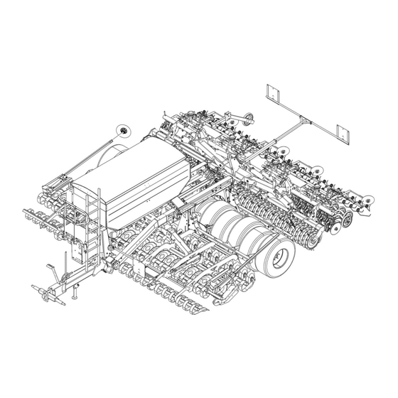
Layout and description Cross shaft Coulter bar Levelling tines Double disc coulters Holder for 10 Carrier for Wheelmark Sowing harrow eradicator discs (not shown) Track Pre-emergence markers levelling plates (not shown) Track marker 11 Impulse wheel Heliodor working section 12 Hopper ... -
Page 43: Lighting Equipment
Layout and description 5.1.1 Lighting equipment Front (1) Rear (2) -
Page 44: Safety Guard
Layout and description 5.1.2 Safety guard Wheelmark eradicator discs and track levelling plates (not shown) Hollow discs, Heliodor working section Double disc coulters, coulter bar (2) 5.1.3 Braking system Air brake system Hydraulic braking system 5.1.4 Stabiliser equipment ... -
Page 45: Transport Locking Device
Layout and description 5.1.5 Transport locking device Soil working implement (1) Coulter bar (2) -
Page 46: Shut-Off Valves
Layout and description 5.1.6 Shut-off valves Transport locking device (1) Soil working implement Track markers Tyre packer roller Coulter bar Pendulum lock right and left (2) For loading only (see separate loading in- structions) Three-point linkage (3) -
Page 47: Description
Layout and description Description 5.2.1 Cross shaft The cross shaft conforms to category 3N, 3, 4N or 4 in accordance with ISO 730-1. Cross shaft L2 Z3 conforms to category Cross shaft L3 Z3 conforms to category 3. Cross shaft L3 Z4 conforms to category Cross shaft L4 Z4 conforms to category 4. -
Page 48: Track Markers
Layout and description Wheelmark eradicator discs The track levelling discs loosen the tractor wheelmarks. The number of wavy discs is determined by the width of the wheel track. Track levelling plates Track levelling plates level the tractor wheelmarks. They are protected from over- loading by a spring. -
Page 49: Side Limitation
Layout and description 5.2.6 Side limitation Side limitation prevents the outer rear right hollow disc and the front left hollow disc from leaving grooves or raising ridges. They are screwed directly onto the frame with their brackets and can be adjusted laterally. 5.2.7 Depth control wheels The depth control wheels enable the im- plement to run more smoothly. -
Page 50: Harrow, Tyre Packer Roller
Layout and description 5.2.9 Harrow, tyre packer roller The tyre packer roller can be fitted with a harrow. The harrow levels any soil which has ac- cumulated between the individual tyres. 5.2.10 3-point interface The coulter bar is attached and removed at the 3-point interface. -
Page 51: Optidisc Coulter Bar / Double Disc Coulter
Layout and description 5.2.12 OptiDisc coulter bar / double disc coulter The seeds are sown in the soil using the OptiDisc double disc coulter for the coul- ter bar. 5.2.13 Sowing harrow The sowing harrow levels slightly uneven ground behind the disc coulter and co- vers the seeds with soil. -
Page 52: Weigher
Layout and description 5.2.5 Weigher The seed hopper can be fitted with a weig- her. The weigher is operated by a dedicated weighing computer on the platform. For operation of the weighing computer, see the separate operat- ing instructions. 5.2.6 Fan The fan transports the seed from the hopper to the seeding coulters via the supply hoses. -
Page 53: Air Brake
Layout and description Air brake Danger due to poor air brake maintenance WARNING A poorly maintained brake system has little or no braking effect. This means long braking distances, rear-ending other vehicles or even the tractor falling over. Make sure the brakes are maintained regularly. ... -
Page 54: Description Of Functions
Layout and description Membrane cylinder (6) Brake cord for parking brake (7) Brake lever (8) 5.3.2 Description of functions The air brake system consists of the following units: Parking brake Operational brake Tear-off brake The individual brake funds are activated depending on when the brake cylinder is actuated. - Page 55 Layout and description Operational brake A compressed air supply from the tractor is required to operate the operational brake. If the device's brake lines are connected to the tractor, the device's air brake sys- tem is supplied with compressed air via the red brake coupling. When the tractor's hand brake or foot brake is pressed, the device begins braking.
- Page 56 Layout and description Disconnecting the brake lines Before removing the device, prevent it from rolling away using the parking brake and chocks. If the brake lines are disconnected from the tractor, the system automatically brakes with the operational pressure of the compressed air container. Shunting ...
-
Page 57: Hydraulic Braking System
Layout and description Hydraulic braking system Danger from poorly maintained braking system A poorly maintained braking system has little or no braking effect. WARNING This may result in long braking distances, rear-end collisions or even overturning of the tractor. Ensure that the brakes are serviced regularly. ... -
Page 58: Functional Description
Layout and description 5.4.2 Functional description The hydraulic braking system consists of the following units: Parking brake Service brake Rapid emergency brake Parking brake The parking brake is used to prevent the implement from rolling away. To activate the parking brake: ... -
Page 59: Preparation Of The Tractor
Preparation of the tractor PREPARATION OF THE TRACTOR Tyres Ensure that all are at the manufacturer's recommended pressures and that left and right hand side tyre pressures are identical. (See manufacturer's instructions)! Lift Rods Adjust lift rods to equal length by means of the adjuster device. (See tractor manu- facturer's instructions) Check Chains or Sway Blocks of the Three Point Linkage Check chains or sway blocks must be adjusted so that the lower links of the trac-... -
Page 60: Lower Control Link Coupling
Preparation of the tractor Lower control link coupling Danger of injury through breakage of mounting studs WARNING A lower control link coupling with an undersize category may cau- se the mounting studs (2) to break. When tractors with a large output are used, the mounting studs (2) may break. -
Page 61: Hydraulic System
Preparation of the tractor Hydraulic system 6.6.1 Transport Lowering the three-point linkage CAUTION The implement may be damaged if the three-point linkage of the tractor is lowered due to an incorrect setting or operation. For transport, always switch the hydraulic system of the three- point linkage of the tractor to "position control". -
Page 62: Power Supply, Electronic Control System
Preparation of the tractor Power supply, electronic control system A supply voltage of 12 V is required for the electronic control system. Undervoltages and overvoltages cause malfunctions and may destroy electrical equipment. Power for the entire electronic control sys- tem is supplied via the power supply cable. The power supply cable is directly connec- ted to the tractor battery. -
Page 63: Connection To The Tractor Battery
Preparation of the tractor 6.7.1 Connection to the tractor battery Ensure that the contact surfaces are clean to provide a good en- ergy flow. The battery installation kit is needed for connection to the tractor battery. The battery installation kit contains: ... - Page 64 Preparation of the tractor Connect the socket connector (4) from the battery installation kit with the plug (6) for the power supply to the coupling box (2). Lock the plug-in connectors (4)+(6). Plug the 8-pin connection cable (7) from the job computer (1) into the operating terminal (8).
-
Page 65: Tractors With Isobus Implement Control
Preparation of the tractor 6.7.2 Tractors with ISOBUS implement control The switch box at the front of the imple- ment contains the following electronic equipment: Job computer (1) Coupling box (2) ISOBUS Gateway (3) ISOBUS connection cable connects the entire ISOBUS implement control system and supplies it with power. -
Page 66: Sockets Required
Preparation of the tractor If no other control devices are connected to the ISOBUS: The orange termination plug (3) is inserted into the socket (2) in the ISOBUS Gateway (1). Sockets required The tractor must have the power sources listed below to supply the electrical con- sumers on the implement: Consumer Power source... -
Page 67: Hydraulic Spool Valves Required
Preparation of the tractor Hydraulic spool valves required In order to activate the hydraulic devices, the tractor must be equipped with the following spool valves: Fan drive Pre-emergence markers Supply: Width section switch Yellow Sowing harrow, hydraulically raised Return: ... - Page 68 Preparation of the tractor Folding Levelling tines / wheelmark eradicator discs and track levelling plates Heliodor working section Platform Trapeze packer roller / harrow Coulter bar Tyre packer roller Working depth, levelling tines Black...
-
Page 69: System Setup, Hydraulic Fan Drive
Preparation of the tractor 6.9.1 System setup, hydraulic fan drive WARNING The hydraulic lines from the fan supply oil for important functions and activate the safety valves. Always connect the fan hydraulic lines to the tractor. If the fan speed falls below the minimum permissible speed, the oil supply to the hydraulic equipment in the fan hydraulics will be too low. -
Page 70: Hydraulic System Configuration
Preparation of the tractor 6.9.2 Hydraulic system configuration The following implement functions are activated by a double-acting spool valve. Function Settings Activation Folding and unfolding Heliodor working section Double-acting Tyre packer roller Operating terminal* spool valve Coulter bar ... -
Page 71: Signal Socket
Preparation of the tractor 6.9.3 Signal socket If the tractor is fitted with radar for speed detection, the speed signal can be selec- ted via the radar system. The speed signal is accessed via the 7-pin signal socket which conforms to DIN 9684. The speed signal is transferred from the signal socket to the operating terminal by an adapter cable. -
Page 72: Preparing The Implement
A range of supply hoses and distributors can be obtained from LEMKEN GmbH & Co. KG. 7.1.2 Changing the metering wheels In the fertiliser configuration, the implement is fitted with a fertiliser-compatible mete- ring system. - Page 73 Preparing the implement Scope of supply For implements which are configured for fertiliser, the following accessories are in- cluded in the scope of supply: (The metering shaft for fertiliser is pre- installed).
- Page 74 Preparing the implement Ref. no. Description Size Quantity Spray can, bodywork protection Hexagon bolt M6x22.5 Hexagon bolt M6x10 Washer D65/20 1x0.5 VA Washer D65/20 1x1 VA Bush D36.5 Bush D31.5 Hose clip 35-50 Hose clamp 25-40 Hose Pulse generator Sensor holder Metering wheel Catch hook Dust cap, front...
-
Page 75: Installing Metering Wheels For Fertiliser On The Implement
Preparing the implement 7.1.3 Installing metering wheels for fertiliser on the implement When distributing fertiliser, a lot of dust may be produced in the metering system. Special dust caps are used to discharge the dust close to the ground and protect the surrounding components from deposi- tion. - Page 76 Preparing the implement Remove the chain (7) Release the spring (9) on the chain ten- sioner (8). Open the chain (7) at the chain fastener. Remove the chain (7). Remove the chain wheel (10) Loosen the threaded pins on the chain wheel (10).
- Page 77 Preparing the implement Metering unit, rear Remove the bolts (2). Remove the perforated plate (1). Installing the metering shaft for fertiliser Components which are supplied with the implement are indicated as follows: (1), (2), (3)… Metering units ...
- Page 78 Preparing the implement Install the holder (11) with the sensor (17). Use the existing nuts (4) and washers. Connect the existing cable (3) to the sensor (17). Install the ball bearing (8) on both sides of the metering shaft. ...
- Page 79 Preparing the implement Install the chain guard (1) Install the chain guard (1) on the holder using a bolt (6), washers and a nut. Install the chain guard (1) directly on the metering system using a bolt (5) and a washer.
- Page 80 Preparing the implement Fit the rear dust cap (15) with bolts (2). Tighten the bolts (2). Hoses Install the hoses (9) on the front and rear dust caps. Fix the hose in place (9) with a hose clip (8).
-
Page 81: Removing The Coulter Bar
Preparing the implement Removing the coulter bar The implement can be fitted with a leading trapeze packer roller or harrow. The leading implements are installed on the coulter bar and are recognised by the electronic implement control system. Leading implements should always be installed and removed by an authorised specialist workshop. - Page 82 Preparing the implement Remove the connections Mark all the connections that will be removed so that you can match them up again at a later date. Remove the connections from the holder (2): Seed hoses Hydraulic lines ...
- Page 83 Preparing the implement Remove the top link Take the load off the top link (1) by turn- ing it. Remove the top link pin (2) from the headstock (3). Hold the top link firmly while doing this. Swivel the top link (1) away from the headstock (3) and place it somewhere safe.
- Page 84 Preparing the implement Store the components in a safe place Install these components on both sides of the catch hook: Locking bar (1) Washer (2) Bolt (3) Nut (4) Install these components on both sides of the cross shaft: ...
-
Page 85: Installing The Coulter Bar
Preparing the implement Installing the coulter bar Risk of injury from unsecured top link pin If the top link pin is not secured, it may slip out or get lost. CAUTION As a result, the device may fall down or be damaged. ... - Page 86 Preparing the implement 3Prepare the components that have been stored If components are installed on the catch hook: Remove the components from both si- des of the catch hook: Locking bar (1) Washer (2) Bolt (3) ...
- Page 87 Preparing the implement Connect the lower links to the cross shaft Reverse the implement up to the un- folded coulter bar. If the lower links are raised: Before lowering the lower links, set the following functions using the electronic control system: ...
- Page 88 Preparing the implement Raise the lower links using the appropri- ate spool valve. The cross shaft is inside the catch hooks and positively connected. Switch off the tractor engine. Secure the tractor and implement so that they do not roll away. ...
- Page 89 Preparing the implement Install the top link Swivel the top link towards the head- stock. Install the top link with the top link pin and secure it. Adjust the top link: Guide distance 750 mm from centre of connection point to centre of connection point The unfolded coulter bar frame is aligned horizontally in relation to the implement.
-
Page 90: Attaching The Implement
Attaching the implement ATTACHING THE IMPLEMENT Danger to life due to unsecured connection between lower link and drawbar If the connection between lower link and drawbar is not secured, the pintle of the drawbar may slip out. DANGER As a result, other road users may be injured or killed while the im- plement is being transported. -
Page 91: Attaching
Attaching the implement Attaching To attach the implements, set the hy- draulic system for the tractor's three- point linkage to position control. Reverse the tractor to the implement so that it is positioned straight in front of the implement and the grab hooks (1) of the lower links (2) can be coupled with the drawbar (3). - Page 92 Attaching the implement Connect the electric cables (5) to the tractor as specified in the table in the "Required hydraulic equipment" section. Connect the brake hoses. Lift the implement several centimetres with the lower links (2). Release the pin (6), pull it out and swing the stand (7) up.
- Page 93 Attaching the implement Close the shut-off valve (12). Close the shut-off valve (13). If the implement is to be transported on public roads, the implement must be equipped with the officially required lighting system with warning plates, and the safety devices must be mounted.
-
Page 94: Driving On Public Roads
Driving on public roads DRIVING ON PUBLIC ROADS General If the implement is transported on public roads: The correct lighting, signs and equipment must be installed on the implement. Ob- serve the standard laws and regulations which apply in your country when travelling on public roads. -
Page 95: Transport Dimensions
Driving on public roads Transport dimensions Danger if implement is raised too high WARNING The folded implement may be too high. This poses an increased risk when driving under bridges, entrances and high-voltage power lines. Observe the maximum transport height. Danger if implement is too wide WARNING The folded implement may be too wide. -
Page 96: Check The Transport Position
Driving on public roads 9.5.1 Check the transport position The implement must be fully raised. See the operating instructions for the electronic control system. Harrow Harrow safely in transport position. See «Harrow, page 149». Sowing harrow Sowing harrow safely in transport positi- on. - Page 97 Driving on public roads Pulse wheel Pulse wheel safely in transport position. See «Pulse wheel, page 158». Track markers Track markers safely in transport positi- on. See «Track markers, page 128».
-
Page 98: Check The Hydraulic Transport Locking Device
Driving on public roads 9.5.2 Check the hydraulic transport locking device Transport locking device, coulter bar: Check that the hook (1) has locked in place correctly. The hydraulic ram must be fully extended (approx. 2 cm). Transport locking device, soil working im- plement, tyre packer: ... -
Page 99: Close The Shut-Off Valves
Driving on public roads 9.5.3 Close the shut-off valves When transporting the implement, close the following shut-off valves: Transport locking device (1) Soil working implement Track markers Tyre packer Coulter bar Three-point linkage (4) -
Page 100: Check The Shut-Off Valves
Driving on public roads 9.5.4 Check the shut-off valves The pendulum system must remain active during transport. Right and left shut-off valves (2) on the pendulum lock are open Illustration: Pendulum system active 9.5.5 Switch off the operating terminal ... -
Page 101: Lights And Signs
Driving on public roads Lights and signs Unfold the front warning board (1) on both sides: Remove the pin (2) and securing pin (3). Unfold the warning board (1). Lock the warning board in place (1) with the pin (2) and securing pin (3). ... - Page 102 Driving on public roads Safety guard, wheelmark eradicator discs and track levelling plates Attach the safety guard to the holder provided using a pin. Secure the pin. Secure the safety guard with a lashing strap. Safety guard, Heliodor working section ...
- Page 103 Driving on public roads Secure the end of the safety guard with a lashing strap: Attach both sides to the Heliodor work- ing section frame Safety guard, coulter bar Feed the lashing strap (3) through the spring pin (1) at the side. ...
-
Page 104: Operation
Operation OPERATION 10.1 Unfolding and folding Risk of accidents due to incorrect folding and unfolding DANGER During folding and unfolding, bystanders may be pushed over by the implement components. Never fold or unfold the implement if anybody is standing in the danger area. - Page 105 Operation Unfolding process The hydraulic transport locking device may seize up after long-term storage or trans- port. To release the hydraulic transport locking device: Briefly move the relevant tractor spool valve in the direction used for folding. The hydraulic transport locking device is released for trouble-free unfolding.
-
Page 106: Folding The Implement
Operation 10.1.2 Folding the implement Damage to the implement Side sections which are not locked in place by the hydraulic transport locking device may unfold unexpectedly during transport if the tractor spool valves are not secured. DANGER This may cause death or injury to other road users while the im- plement is being transported. - Page 107 Operation Move the harrow into the transport posi- tion, see «Harrow, page 149». Move the pulse wheel into the transport position, see «Pulse wheel, page 158». Secure the track markers in the transport position, see «Track markers, page 128».
- Page 108 Operation Folding process Lift and fold the implement using the operating terminal and spool valve. See the operating instructions for the electro- nic control system. The implement is folded by means of the hydraulic rams in the predefined sequence: ...
-
Page 109: Sequence Control
Operation 10.2 Sequence control Risk of accidents due to moving implement components WARNING Automatically controlled implement components may injure people in the danger area. Before activating sequence control, ensure that nobody is standing within the operating or swing radius of the implement. Sequence control includes lifting and lo- wering of the following implement compo- nents:... -
Page 110: Operating Modes
Operation For more information on the sequence control process, see the operating instructions for the electronic control system. 10.2.1 Operating modes The following operating modes allow lifting and lowering of all implement components in sequence or of individual implement components. ... -
Page 111: Stopping Sequence Control
Operation Manual mode In manual mode the individual implement components can be activated and deac- tivated independently of one another. All activated implement components are lifted or lowered at the same time. The following implement components can be activated or deactivated: ... -
Page 112: Setting The Lift Sensor For The Soil Working Implement
Operation 10.2.3 Setting the lift sensor for the soil working implement Note that the implement lift height is different on the return pass on the headland. The metering system is activated when the lift sensor for the soil working implement switches. -
Page 113: Filling The Hopper
Operation 10.3 Filling the hopper DANGER In a high wind the cover may swing downwards in an uncontrol- led manner. The cover is under spring tension. The agitator shaft can rotate. Do not place any parts in the hopper. ... -
Page 114: Unfolding The Filling Screw
Operation 10.3.2 Unfolding the filling screw To unlock the filling screw (1): Remove the pin (2) from the holder (3). Swing the filling screw (1) out comple- tely, keeping it horizontal. To move the filling screw into position: ... - Page 115 Operation To move the platform out of the way: Unlock the steps (6) using the lever (5). Move the steps (6) into position. Before unfolding the filling screw any further: Open the hopper cover. Remove the pin (7) and securing pin from the handrail.
-
Page 116: Operating The Filler Hopper
Operation Engage the lock (10) on the filling screw (1). 10.3.3 Operating the filler hopper Swivel the filler hopper (1) over the con- tainer to be filled. Switch the cut-off valve (2) to filler hop- per mode. ... - Page 117 Operation Open the valve (3) to start the filler hop- per. Close the valve (3) to stop the filler hop- per. The filler hopper (1) rotates depending on the lever position of the valve (3). The wider the valve is opened, the faster the filler hop- per rotates.
-
Page 118: Emptying The Filling Screw
Operation 10.3.4 Emptying the filling screw Crush risk from rotating filling screw CAUTION Reaching into the filling screw may cause injuries to the hands and fingers. Never reach into the filling screw through the open flap. Keep a safe distance away. To remove any remaining seed/fertiliser from the filling screw: ... -
Page 119: Folding The Filling Screw
Operation 10.3.5 Folding the filling screw Release the lock (10) on the filling screw (10). Remove the pin (7) and securing pin from the handrail. Lift the strut (8) on the handrail upwards. Hold the strut (8) with one hand. ... - Page 120 Operation Push the steps (6) completely onto the platform. Lock the steps (6) using the lever (5). To move the filling screw into the horizon- tal position: Pull the funnel (4) on the filling screw (1) upwards. ...
-
Page 121: Closing The Hopper
Operation To lock the filling screw (1) in place: Insert the pin (2) into the holder (3). 10.3.6 Closing the hopper Before closing the hopper: Fold the filling screw. After filling, close the cover (2). Release the support. ... -
Page 122: Working With The Implement
Operation 10.4 Working with the implement 10.4.1 Stopping the implement in an emergency Stop the implement from the tractor. Switch off the tractor engine. Remove the ignition key. 10.4.2 Working lights with hopper light The LED working lights (1) and hopper light are switched on and off from the ope- rating terminal. -
Page 123: Turning At The Headland
Operation 10.5 Turning at the headland DANGER Risk of damage to components If the implement is not fully raised, there is a danger that compo- nents may be damaged during an improper turn at the headland. Before turning at the headland the implement must be completely raised before turning-in to avoid any damage to the implement. -
Page 124: Settings
Settings SETTINGS Risk of accidents during adjustment work During all adjustment work on the implement there is a risk of crushing, cutting, trapping or knocking the hands, feet or body on heavy parts which may be under spring pressure and/or have sharp edges. - Page 125 Settings Every time the coulter bar is actuated hydraulically and when the tilling device is raised or lowered, the track markers are also fold- ed in and out at the same time. The only time the track markers do not fold in and out is when they are: DANGER ...
-
Page 126: Wheelmark Levelling
Settings 11.1 Wheelmark levelling The wheelmark eradicator discs and track levelling plates are mounted on a holder. The tools can be positioned to fit the trac- tor wheelmark. 11.1.1 Adjusting the wheelmark eradicator discs The wheelmark eradicator disc is mounted on the holder with U-bolts (1) and a clam- ping plate (3). -
Page 127: Adjusting The Track Levelling Plates
Settings 11.1.2 Adjusting the track levelling plates The bracket (1) for the track levelling plate is mounted with a combination of eyebolts (2) and hexagon bolts (5). To change the position of the track le- velling plate: Loosen the nuts (4) on the hexagon bolts (5). - Page 128 Settings Before adjustment Remove the fastenings on the tool (1). Remove the tool (1). The spring pressure can be increased or reduced in stages by moving the lever (5) to the required position. Remove the circlip (6). ...
-
Page 129: Limiting The Lift With Hydro-Clips
Settings 11.1.3 Limiting the lift with hydro-clips Crushing hazard CAUTION The hydro-clips are under spring pressure during installation. They may crush hands or fingers if they spring back in an uncon- trolled manner. Install hydro-clips in a controlled manner using both hands. The working depth of the track levelling discs is set using the hydraulic ram (2) -
Page 130: Track Markers
Settings To reduce the working depth: Add the required number of hydro-clips (3) to the piston rod. 11.2 Track markers WARNING Never stand within the folding range of the track marker. Unfolded, deactivated track markers fold inwards when the spool valve is operated, even though they have been deactivated. -
Page 131: Secure The Track Marker
Settings 11.2.2 Secure the track marker Before any driving on public roads, or adjustment and maintenance work, the track marker must be secured in the folded-in position. Remove the bolt (1) from the swinging arm (3) of the track marker using the se- curing pin (2). -
Page 132: Adjust Track Marker
Settings 11.2.4 Adjust track marker The track markers must be adjusted to the middle of the tractor track based on the ta- ble below. Release the clamping screws (1). Adjust the length of the track marker arm (2). ... -
Page 133: Sowing Shaft For Seeds
Settings 11.3 Sowing shaft for seeds The sowing shaft (1) has 6 sowing rollers for each sowing system: Fine seed roller (3) 2 narrow seed rollers (4) 3 broad seed rollers (5) There are separator discs between each of the seed rollers to ensure that the individu- al seed rollers work independently. -
Page 134: Switching The Sowing Rollers On Or Off
Settings 11.5 Switching the sowing rollers on or off Danger of injury due to rotating sowing shaft WARNING There is a danger of injury when the operating terminal is switched on and the sowing shaft is rotating. Before working on the sowing rollers, always switch off the con- trol terminal of the electronic controller. -
Page 135: Activating The Sowing Rollers
Settings 11.5.1 Activating the sowing rollers A sowing roller is activated by screwing in the stop screw (3). When unscrewing the stop screw, make sure that it is always exactly screwed into the groove (6) of the sowing shaft (7) and located within the perimeter of the sowing roller. The stop screw must be screwed in far enough that it is still located within the perimeter of the sowing roller and not jammed with the sowing shaft (7). -
Page 136: Deactivating The Sowing Rollers
Settings 11.5.2 Deactivating the sowing rollers Read and observe the general safety instructions and the CAUTION "Maintenance" safety instructions. In the "Unscrewing Test" menu and when the pulse wheel is turned, the sowing rollers, sowing shaft, and agitator shaft turn as well. -
Page 137: Stop Slides
Settings 11.6 Stop slides During operation all slide plates (1) must be fully opened. If necessary the seed flow from the hopper to the metering units can be stopped by means of one or more slide plates (switch of width sections). As an option the slide plates can be oper- ated via hydraulic rams (2) from the tractor seat via the operation terminal of the elec-... -
Page 138: Shut-Off Slider - Hydraulic
Settings 11.7.2 Shut-off slider - hydraulic For hydraulic section width shut-off, there is a hydraulic cylinder (2) above the shut- off slider (1). It is actuated through the con- trol terminal. The blower's hydraulic system is used to supply it with oil. See the operating instructions for the elec- tronic control system. -
Page 139: Setting The Bottom Gates For Seed
Settings 11.8.1 Setting the bottom gates for seed Move the lever (3) into one of the follo- wing positions, depending on the seed to be distributed: Position 1 Position 2 None of the other positions are required in this case. -
Page 140: Unscrewing Test
Settings 11.9 Unscrewing test CAUTION During the unscrewing test, watch out for the danger areas for rotating and oscillating components. The unscrewing test can be carried out once the seeding rollers and the bottom gates have been adjusted according to the seeding table. See the operating in- structions for the electronic controller. -
Page 141: Agitator Shaft
Settings 11.10 Agitator shaft The agitator shaft (1) must be switched off for delicate seed. Pull the linch pin (3) out of the gear wheel (2) on the agitator shaft (1). -
Page 142: Using The Agitator Fingers
Settings 11.10.1 Using the agitator fingers CAUTION Risk of crush injuries from the agitator shaft A rotating agitator shaft may cause injuries. Switch the agitator shaft off before installing the agitator fingers. Only use the agitator fingers for grass seeds. With other seed types, additional agitator fingers may adversely affect the distribution rate. -
Page 143: Electronic Level Indicator
Settings 11.11 Electronic level indicator The level is monitored electronically by a sensor (1). The sensor (1) triggers an alarm if contact with the seed/fertiliser is interrupted. The sensor holder swivels so that the fill level can be monitored at the height requi- red. -
Page 144: Converting Coulter
Settings 11.12.1 Converting coulter If worn, the coulters (2) on the stalk (1) can be converted as follows: Remove the screws (2). Adjust the coulter (3) into the hole re- quired. Fix the screws (2). Tighten the screws (2) to 113 Nm. 11.12.2 Rotate coulters To achieve an aggressive or flat levelling... -
Page 145: Working Depth Adjustment, Heliodor Working Section
Settings 11.13 Working depth adjustment, Heliodor working section 11.13.1 Limiting the lift with hydro-clips Crushing hazard CAUTION The hydro-clips are under spring pressure during installation. They may crush hands or fingers if they spring back in an uncon- trolled manner. ... - Page 146 Settings Fully extend the hydraulic ram (2) before setting the working depth: Raise the implement completely. To increase the working depth: Remove the required number of hydro- clips (3) from the piston rod. To reduce the working depth: ...
-
Page 147: Adjusting The Lateral Limiter
Settings 11.13.2 Adjusting the lateral limiter The side shields ensure that the next pass is lined up accurately. To adjust the side shields to the working width required: Loosen the bolts (1). Move the lateral limiter (6) along the car- rier. -
Page 148: Adjusting The Depth Control Wheels
Settings 11.13.3 Adjusting the depth control wheels The depth of the depth control wheel is de- termined by the hole setting. The depth is correctly set when the depth control wheel is touching the soil lightly. The depth control wheel is lifted via the sequence control system with the Heliodor working section. -
Page 149: Setting The Working Depth, Harrow And Tyre Packer Roller
Settings 11.14.1 Setting the working depth, harrow and tyre packer roller Loosen the nut (6) and washer (5). Loosen the clamping plate (4). Place bars between the clamping plate (4) and the holder (1). Replace the nut (6) and washer (5). ... -
Page 150: Checking And Setting The Scraper
Settings 11.15.1 Checking and setting the scraper The clearance between the scraper (1) and the roller sleeve must be 0.1–0.5 mm. The scraper (1) must not touch the roller sleeve in any position. To check the setting: Turn the roller through 360 The scraper (1) is adjusted as follows: ... -
Page 151: Harrow
Settings 11.16 Harrow 11.16.1 Transport position Before any driving on public roads, the harrow (1) must be brought into the transport position. Dismount the bolt (4) using the safety pin (3). Fit a 50mm open-end spanner (6) on the lever (2). -
Page 152: Adjust The Contact Angle
Settings 11.16.2 Adjust the contact angle. Dismount the bolt (4) using the safety pin (3). Fit a 50mm open-end spanner (6) on the lever (2). Swivel the harrow (1) into the required position over the lever using the 50mm open-end spanner (6). -
Page 153: Levelling Bar
Settings 11.16.4 Levelling bar A height adjustable levelling bar can be bolted onto the tines (9) of the harrow (1) to enhance the levelling effect of the har- row (1). 11.17 Coulter bar 11.17.1 Checking and setting the height The height of the coulter bar differs depen- ding on the leading implement. - Page 154 Settings Implement with roller The height of the coulter bar is determined by the roller. The pre-set roller pressure controls the height of the coulter bar. The distance from the underside of the frame tube (1) to the ground is approx. 320 mm, depending on deposition depth.
-
Page 155: Double Disc Coulter
Settings 11.18 Double disc coulter The double disc coulters are fitted with strippers made from vulcanised material. Hard metal strippers are also available. 11.18.1 Strippers for double disc coulters The double disc coulters (1) are fitted with self-adjusting strippers (3). The individual stripper (3) is placed on the holder (4). -
Page 156: Deposition Depth Of The Seeding Coulters
Settings 11.18.3 Deposition depth of the seeding coulters If necessary, adjust the length of the top 750 mm link (2): Guide distance 750 mm (centre of connec- tion point to centre of connection point) The deposition depth is adjusted with the turnbuckles (1). -
Page 157: Adjusting The Coulter Pressure
Settings 11.18.4 Adjusting the coulter pressure OptiDisc M double disc coulters The coulter pressure can be adjusted me- chanically at the double disc coulter by means of connecting rods with compres- sion springs (1). The tension of the compression spring (1) can be increased or reduced incrementally on the adjustment lever (2). - Page 158 Settings Increasing the coulter pressure To increase the coulter pressure, tighten the compression spring (1): Place the spanner (3) on the adjustment lever (2). Turn the spanner (3) anti-clockwise. Turn the adjustment lever (2) to a higher setting.
-
Page 159: Lane Mode
Settings OptiDisc double disc coulters The hydraulic coulter pressure adjustment system is supplied with oil via the fan drive. Therefore the coulter pressure can only be generated and changed when the fan is running. The coulter pressure can be adjusted on the operating terminal for the electronic control system via the hydraulic unit on the coulter frame. -
Page 160: Pulse Wheel
Settings 11.20 Pulse wheel CAUTION Risk of injury due to rotating implement components When the pulse wheel rotates, the metering wheels, metering shaft and agitator shaft also rotate. Keep a safe distance away. The pulse wheel transmits speed signals to the electronic control system. -
Page 161: Transport Position
Settings 11.20.1 Transport position Move the pulse wheel into the transport position before travelling on public roads. Remove the pin (2) and linch pin (3). Swivel the wheel arm (1) upwards. Secure the wheel arm (1) with the pin (2) and linch pin (3). -
Page 162: Operating Position
Settings 11.20.2 Operating position Fix the wheel arm (1) in place. Remove the pin (2) and linch pin (3). Swivel the wheel arm (1) downwards. Secure the wheel arm (1) with the pin (2) and linch pin (3). The pulse wheel is in the operating positi-... -
Page 163: Checking And Setting The Working Depth
Settings 11.20.3 Checking and setting the working depth The sowing harrow must not touch the pulse wheel during opera- tion. Ensure that there is sufficient clearance. When the coulter bar is raised, the pulse wheel (4) must be 0–5 cm lower than the pressure rollers on the double disc coul- ters. -
Page 164: Fan
Settings 11.21 Fan Seed and fertiliser are transported to the coulters in an air flow produced by the fan (1). The speed of the fan (1) is set by adjusting the oil volume using the tractor spool val- ve. The current speed is displayed on the operating terminal for the electronic control system. -
Page 165: Tractor Spool Valve Without Flow Control Valve
Settings 11.22.1 Tractor spool valve without flow control valve The speed is set by means of the following flow control valves: Fan drive on the implement Fully open the flow control valve (1) u- sing the adjusting knurl (2). ... -
Page 166: Fertiliser Version
Settings 11.23 Fertiliser version The blower for the precision planter can be driven hydraulically via: direct supply double control valve Observe the additionally required oil quantity of the tractor for the precision plan- ter. See also the operating manual of the precision planter. 11.24 Direct supply The separate hydraulic hose for the precision seed drill runs as far as the imple- ment interface. -
Page 167: Tractor Spool Valve With Flow Control Valve
Settings 11.24.2 Tractor spool valve with flow control valve Operation with a precision seed drill The speed is set by means of the following flow control valves: Tractor spool valve, fan drive on imple- ment Tractor spool valve, fan drive on precisi- on seed drill ... -
Page 168: Double Flow Control Valve
Settings 11.25 Double flow control valve The double flow control valve allows the oil volume required for the implement and the precision seed drill to be adjusted separately. 11.25.1 Tractor spool valve without flow control valve Operation with a precision seed drill The speed is set by means of the following flow control valves: ... - Page 169 Settings Operation without a precision seed drill Open the shut-off valve (5), as shown in the illustration. Fully close the flow control valve (3) u- sing the adjusting knurl (4). Set the fan speed, see «Tractor spool valve without flow control valve, page 163».
-
Page 170: Tractor Spool Valve With Flow Control Valve
Settings 11.25.2 Tractor spool valve with flow control valve Operation with a precision seed drill The speed is set by means of the following flow control valves: Tractor spool valve Fan drive on implement Fan drive on precision seed drill ... - Page 171 Settings Operation without a precision seed drill Open the shut-off valve (5), as shown in the illustration. Fully close the flow control valve (4) u- sing the adjusting knurl (3). Set the fan speed, see «Tractor spool valve with flow control valve, page 163».
-
Page 172: Sowing Harrow
Settings 11.26 Sowing harrow Risk of injury from sharp components CAUTION The sowing harrow tines may cause injuries. Move the sowing harrow into the transport position before tra- velling on public roads. Park an implement with a sowing harrow in the transport positi- The sowing harrow must not touch the pulse wheel during opera- tion. -
Page 173: Transport Position
Settings 11.26.1 Transport position Remove the pin (3) and securing pin. Lift the frame (5). Remove the pin (4) and securing pin. Move the frame (5) into the transport po- sition. Fix it in position with pins (3)+(4) and a securing pin. -
Page 174: Setting The Angle
Settings 11.26.2 Setting the angle The sowing harrow angle can be adjusted using the pins (3)+(4) in the frame (5). The top pin (3) limits the angle. The lower pin (4) acts as a stop. To minimise wear on the tines (6): Set the angle so that the horizontal part of the tines (6) rises slightly in the direction of travel (angle 5–10°). -
Page 175: Setting The Harrow Pressure
Settings 11.26.3 Setting the harrow pressure The harrow pressure is set by adjusting the tension of the compression spring (1). The compression spring (1) is held in place by a threaded connection (2) with washers and can be turned by hand. ... -
Page 176: Setting The Working Depth
Settings 11.26.4 Setting the working depth The working depth is set by adjusting the length of the guide bar (7). The position of the guide bar (7) is fixed between discs (5)+(6) using a spring pin (4). To change the working depth: ... -
Page 177: Hydraulic System For Raising The Sowing Harrow
Settings 11.26.5 Hydraulic system for raising the sowing harrow A hydraulic cylinder (1) for raising the har- row is available as on request. The oil for the hydraulic cylinder (1) is sup- plied through the oil circuit for the hydraulic motor for the blower. -
Page 178: Setting The Track Width
Settings 11.27.1 Setting the track width The hollow discs can be adjusted exactly to the track width of the tractor: Move the pre-emergence markers on the carrier Adjust the hollow discs on the disc car- rier Moving the pre-emergence markers on the carrier ... -
Page 179: Setting The Marker Depth
Settings 11.27.2 Setting the marker depth The marker depth is set by adjusting the tension of the compression spring (1). The compression spring (1) is held in place by a threaded connection (2) with washers and can be turned by hand. ... -
Page 180: Adjusting The Transport Locking Device, Soil Working Implement
Settings 11.28 Adjusting the transport locking device, soil working implement The frame of the tyre packer roller (1) must be firmly locked onto the frame of the soil working implement (2). If the locking devices (3)+(4) do not close properly, adjust the locking devices (3)+(4) by moving the support plate (7). -
Page 181: Cleaning And Care
Cleaning and care CLEANING AND CARE 12.1 Cleaning the implement Particularly after spreading fertiliser, the implement must be carefully cleaned u- sing compressed air and water. Clean the sowing unit daily. Remove residual fertiliser. Empty the container after use and clean this with compressed air. Store the implement dry after use. -
Page 182: Emptying The Hopper
Cleaning and care 12.3 Emptying the hopper Depending on the remaining quantity, empty the hopper as follows: Larger remaining quantities: Empty u- sing the individual distributors. Smaller remaining quantities: Empty u- sing the calibration tray. 12.3.1 Emptying using the distributor The hopper is emptied pneumatically using the fan. - Page 183 Cleaning and care Remove the distributor point (7). Install the connector (5) and hose (4) on the distributor (6). Switch on the fan. The remaining quantity is discharged via the distributor (6). When the hopper is empty: ...
-
Page 184: Emptying Using The Calibration Tray
Cleaning and care 12.3.2 Emptying using the calibration tray Remove the calibration tray (2) from the holder. Push the calibration tray (2) under the metering unit. Swivel the flaps (1). To open the bottom gates: Fully open the bottom gate lever (3). The remaining quantity is collected in the calibration tray (2). -
Page 185: Uncoupling The Implement
Uncoupling the implement UNCOUPLING THE IMPLEMENT CAUTION Tipping hazard The parked implement may tip over, causing crushing or fatal inju- ries. Always park the implement on a stable, level surface. Danger from rolling tractor and implement DANGER There is a risk of serious injury or death if the tractor or implement rolls away while you are standing between them. - Page 186 Uncoupling the implement Set the hydraulics of the tractor's 3-way linkage to position control. Release the pin (6) of the stand (7) and pull it out. Lower the stand (7). Lock the stand (7) with the pin (6) and lock the pin (6) with the securing pin.
- Page 187 Uncoupling the implement Close the shut-off valve (12). Close the shut-off valve (13). Take the wheel chocks (8) out of the holder (9) and secure the implement against rolling.
- Page 188 Uncoupling the implement Actuate the parking brake (11). Disconnect the electric cables. Disconnect the brake hoses. In conjunction with an air brake system: the system automatically brakes with the operational pressure of the compressed air container. Move the activation lever of the control unit in the floating position to depressur- ise the hydraulic hoses.
-
Page 189: Maintenance And Servicing
Maintenance and servicing MAINTENANCE AND SERVICING 14.1 Specific safety information 14.1.1 General Risk of injury There is a risk of injury during maintenance and repair work. Always use suitable tools, suitable access aids, platforms and WARNING supports. Always wear personal protective equipment. ... -
Page 190: Immobilise The Implement For Maintenance And Repairs
Maintenance and servicing 14.1.4 Immobilise the implement for maintenance and repairs Risk of accidents when tractor starts up Injuries may occur if the tractor starts moving during maintenance and repair work. Switch off the tractor engine before carrying out any work on the WARNING implement. -
Page 191: Working Under The Raised Device
Maintenance and servicing 14.1.7 Working under the raised device Risk of accident due to lowering and extending of compo- nents and devices It is extremely dangerous to work under raised or next to retracted components and devices. WARNING Always secure the tractor to prevent it from rolling away. ... -
Page 192: Environmental Protection
Maintenance and servicing Risk of accident due to tool slipping off If applying a large force, e.g. when loosening bolts, the tool may WARNING slip off. This may result in hand injuries on sharp-edged parts. Avoid applying a large force by using suitable auxiliary equip- ment (e.g. -
Page 193: Maintenance Schedule
Maintenance and servicing 14.3 Maintenance schedule Drawbar Cross shaft joint ● ● ● Drawbar joint ● ● ● Working section Hydraulic ram, ● ● ● levelling tines Hydraulic ram, wheelmark eradi- ● ● ● cator discs Hydraulic ram, ● ● ●... - Page 194 Maintenance and servicing Hopper / metering system Air pipe ● ● ● ● ● ● Metering unit for fertiliser ● ● ● Metering unit for ● ● ● seed Metering wheels ● ● Bottom gates ● ● Cyclone ● ● ●...
- Page 195 Maintenance and servicing Three-point linkage Catch hook ● ● Cross shaft ● ● Top link ● ● Hydraulic ram ● ● ● Lift linkage Joint, lift linkage ● ● ● Leading implements Scrapers, roller ● ● Coulter bar Joint, frame ●...
- Page 196 Maintenance and servicing Grease surfaces Track levelling ● ● discs Disc coulters ● ● Wheelmark eradi- ● ● cators Piston rod, hydrau- lic rams ● ● Use acid-free grease! Pins ● ● Air brake system Compressed air ● ● tank Filter ●...
-
Page 197: Lubrication
Maintenance and servicing 14.4 Lubrication Eye injuries due to grease WARNING When lubricating the lubrication points, grease can escape be- tween components at high pressure and cause injury to the eyes. In case of injury, seek medical attention immediately. Wear protective clothing during lubrication, particularly goggles. ... -
Page 198: Lubricating The Drawbar
Maintenance and servicing 14.4.1 Lubricating the drawbar Lubricate the grease nipples (1)+(2) on the cross shaft joint Every 50 operating hours At least once a year before the winter break Lubricate the grease nipple (3) on the drawbar joint ... -
Page 199: Lubricating The Working Section
Maintenance and servicing 14.4.2 Lubricating the working section Levelling tines Right + left sides of the implement: Lubricate the grease nipples (1)+(2) on the hydraulic ram Every 50 operating hours At least once a year before the winter break Wheelmark eradicator discs and track levelling plates Right + left sides of the implement:... - Page 200 Maintenance and servicing Folding frame Right + left sides of the implement: Lubricate the grease nipples (1)+(2) on the hydraulic ram Every 50 operating hours At least once a year before the winter break Side section Right + left sides of the implement: ...
-
Page 201: Lubricating The Track Markers
Maintenance and servicing 14.4.3 Lubricating the track markers CAUTION Crushing hazard There is a risk of crushing your fingers or hand when working in the joint area of the track marker. Secure the track marker to prevent uncontrolled movements. ... -
Page 202: Lubricating The Tyre Packer Roller
Maintenance and servicing 14.4.4 Lubricating the tyre packer roller Lubricate the grease nipple (1) on the hydraulic ram for the frame on the right and left sides: Every 100 operating hours At least once a year before the winter break ... -
Page 203: Axle
Maintenance and servicing 14.4.5 Axle Running axles Wheels on the side sections: Lubricate the grease nipple (1) on the wheel bearing (max. 10 cm³ grease): Every 100 operating hours At least once a year before the winter break Braking axles ... -
Page 204: Steps, Platform
Maintenance and servicing Axle bearings Axle bearings must be checked for play and wear, and adjusted if necessary, by an authorised person: Every 6 months The axle bearing grease must be changed by an authorised person: At least once a year before the winter break 14.4.6 Steps, platform ... -
Page 205: Lubricating The Filling Screw
Maintenance and servicing 14.4.7 Lubricating the filling screw Lubricate the grease nipple on the joint (1): Every 100 operating hours Lubricate the grease nipple on the joint (2): Every 100 operating hours Lubricate the grease nipple on the joint (3): ... -
Page 206: Lubricating The Three-Point Linkage
Maintenance and servicing 14.4.8 Lubricating the three-point linkage Before carrying out lubrication work, lower the mounted implement onto the ground and depressurise it. Lubricate the grease nipple (1) on the hydraulic ram for the lift linkage: Every 50 operating hours ... -
Page 207: Lubricating The Coulter Bar
Maintenance and servicing 14.4.10 Lubricating the coulter bar Before carrying out lubrication work, lower the mounted implement onto the ground and depressurise it. Lubricate the grease nipple (4) on the hydraulic ram for the folding system on the right and left sides: ... - Page 208 Maintenance and servicing Sowing harrow Lubricate the grease nipple (1) on the swinging arm joint: At least once a year before the winter break Lubricate the grease nipple (2) on the sowing harrow joint: Every 100 operating hours ...
-
Page 209: Tyres
Maintenance and servicing 14.4.11 Tyres Risk of accidents due to incorrect tyre pressure Tyres may burst if they are inflated beyond the recommended tyre WARNING pressure. Tyres will be overloaded if they are not inflated suffi- ciently. This has a negative impact on the implement's ability to follow the correct track, which obstructs and endangers road users. -
Page 210: Wheel Nuts
Maintenance and servicing 14.4.12 Wheel nuts Check the wheel nuts: After the first 8 operating hours Every 50 operating hours Tighten the wheel nuts diagonally using a torque spanner, see «Tightening tor- ques, page 228». 14.4.13 Threaded connections Check the threaded connections: ... -
Page 211: Air Brake System
Maintenance and servicing 14.6 Air brake system 14.6.1 Draining the compressed air tank The condensation water must be drained out of the compressed air tank (2) regu- larly. Pull or push the pin (1) on the drain val- ve sideways. The condensation water is forced out of the compressed air tank with the compres- sed air. -
Page 212: Checking The Scrapers On The Trapeze Packer Roller
Maintenance and servicing 14.7 Checking the scrapers on the trapeze packer roller Before use: Check that the clearance between the scrapers (1) and trapeze packer roller is correct and adjust it if necessary. See «Checking and setting the scraper, page 148». -
Page 213: Checking The Distributors
Maintenance and servicing 14.8 Checking the distributors The distributors (1) have screw-on distribu- tor points (2) which make it easy to carry out a visual inspection of the distributors. Remove the distributor points. Check the distributors for blockages and clear them if necessary. - Page 214 Maintenance and servicing Before cleaning Close the slide (2). Move the calibration tray (3) into positi- Open the flaps (4). Remove the protective cover (5). Fully open the bottom gates using the lever (6). Cleaning ...
-
Page 215: Cleaning The Sowing Units For Fertiliser
Maintenance and servicing 14.10 Cleaning the sowing units for fertiliser. Contact with fertiliser DANGER Wear suitable protective gear when cleaning. Cleaning should ideally take place on the last area treated. The cleaning water should not seep into the groundwater or sewer systems. -
Page 216: Check The Sowing Rollers
Maintenance and servicing The feeding units (1) must be maintained regularly; at least once a day. Close the shut-off valve (2). Move the calibration tray (3) into posi- tion. Open the drain gates (4). Remove the dust caps (5). ... - Page 217 Maintenance and servicing Rotate the sowing shaft using a 17 mm open-ended spanner until the stop screws are easy to reach. Screw the stop screws out with a 8 mm box spanner and a 3 mm hexagon sock- et spanner.
-
Page 218: Checking The Bottom Gates
Maintenance and servicing 14.11.1 Checking the bottom gates Keep the distance of the bottom gate (2) to the sowing roller (1) as small as pos- sible. But the sowing roller (1) may not touch the bottom gate (2). Check the clearance by manually rota- ting the sowing roller (1). -
Page 219: Fan
Maintenance and servicing 14.13 Fan The fan is fitted with a cyclone. The cyclo- ne removes dust from the intake air. The dust is automatically ejected. If the cyclone is dirty, the fan performance declines, resulting in incorrect distribution of the seed/fertiliser. 14.13.1 Checking the cyclone CAUTION... -
Page 220: Cleaning The Cyclone
Maintenance and servicing 14.13.2 Cleaning the cyclone Open the cap (4). Remove the cover (3) with the hose. Clean the cyclone with compressed air. After cleaning: Replace the cover (3). Close the cap (4). -
Page 221: Checking Connections To The Tractor
Maintenance and servicing 14.14 Checking connections to the tractor 14.14.1 Couplings Risk of accident due to spraying hydraulic fluid Fluid (hydraulic oil) escaping under high pressure can penetrate WARNING the skin and cause severe injuries. In case of injury, seek medical attention immediately. -
Page 222: Hydraulic Lines
Maintenance and servicing 14.15 Hydraulic lines Hydraulic lines must be checked regularly for damage and leaks. Damaged or leaking lines must be replaced immediately. Hydraulic hoses must be replaced at the latest 6 years after the date of manufacture printed on the hydraulic hoses. Only hydraulic hoses approved by the im- plement manufacturer may be used. -
Page 223: Troubleshooting
Troubleshooting TROUBLESHOOTING Risk of accidents DANGER If the implement is not shut down, components may move unex- pectedly or the implement may start to move. This may cause se- rious injuries or death. Shut the implement down before carrying out any work. -
Page 224: Decommissioning And Disposal
Decommissioning and disposal DECOMMISSIONING AND DISPOSAL Damage caused by improper storage of the implement If incorrectly or improperly stored, the implement may be dam- CAUTION aged, e.g. by humidity and dirt. The implement should be deposited on a flat and adequately sta- ble base only. -
Page 225: Technical Data
Technical data TECHNICAL DATA 17.1 Dimensions Designation Value Unit Length minimum 8,150 mm maximum 9,230 mm Width 3,000 mm Height 3,620 mm Reach / span minimum 4,930 mm maximum 5,350 mm... -
Page 226: Weights
Technical data 17.2 Weights The actual gross weight may vary depending on the equipment installed. The implement must be weighed in order to obtain an accurate weight. Designation Value Unit Minimum gross weight, empty 9,138 kg Permissible gross weight 15,000 * kg Permissible axle load 11,500 * kg Permissible drawbar load... -
Page 227: Performance Data
Technical data 17.5 Performance data Description Value Unit Maximum speed Smooth road 25** / 40 km/h Rough terrain * km/h Tractor output from / to 132 – 221 / kW / hp 180 – 300 Permissible tractive power of the tractor: ... -
Page 228: Braking System
Technical data 17.8 Braking system Description Value Unit All axles 12 Quantity Braking axle 6 Quantity Running axle 6 Quantity Air brake system Description Value Unit Diaphragm cylinder 6 Quantity Diameter 12 Inch Does not apply in France Hydraulic braking system Description Value Unit... -
Page 229: Tyres
Technical data 17.9 Tyres For safety reasons, do not inflate the tyres above or below the permissible tyre pressure. Description Value Unit Tyre size 420/65 R20 128 A8 12 Quantity Make: Mitas AC 65 Minimum tyre pressure 1.4 bar ... -
Page 230: Tightening Torques
Technical data 17.12 Tightening torques 17.12.1 General information Once loosened, secure self-locking nuts against self-loosening by exchanging the nuts with new self-locking nuts. using safety washers. using thread-locking compounds, such as Loctite. The following tightening torques refer to screw threaded fittings not specifically mentioned in these operating instructions. -
Page 231: Bolts And Nuts Made Of Steel
Technical data 17.12.2 Bolts and nuts made of steel Strength category Diameter 10.9 12.9 [Nm*] [Nm*] [Nm*] 13,6 16,3 23,4 32,9 39,6 M 10 46,2 64,8 77,8 M 12 80,0 M 14 M 16 M 20 M 24 1112 M 30 1314 1850 2217... -
Page 232: Bolts And Nuts Made Of V2A
Technical data 17.12.3 Bolts and nuts made of V2A Diameter [Nm] 1.37 11.0 M 10 M 12 M 14 M 16 M 18 M 20 M 22 M 24 M 27 17.12.4 Wheel bolts and wheel nuts Diameter / thread [Nm] M18 x 1,5 M20 x 1,5... -
Page 233: Annex
Annex ANNEX 18.1 Seed table Seed Working width [kg/ha] [kg/ha] [kg/ha] [kg/ha] [kg/ha] [kg/ha] 500 | 1000 35-100 100-220 220-300 450 | 900 40-110 110-240 240-300 Cereals 400 | 800 45-120 120-260 260-300 300 | 600 |1200 30-80 80-180 180-260 260-300 500 | 1000 50-110... -
Page 234: Index
Index INDEX 3-point interface ....................48 AEF conformity ....................26 Agitator fingers ....................140 Agitator shaft ...................... 139 Air brake ....................... 51 Air brake system ....................209 Attaching ....................... 89 Axle ........................201 Bottom gates ...................... 136 Braking system ................42, 92, 208, 226 Check Chains ....................... - Page 235 Index Fan ......................162, 217 Fan drive ....................... 67, 175 Feeding units ...................... 213 Fill levels ......................225 Filling screw ......................203 Folding ........................ 102 Harrow ....................48, 147, 149 Heliodor ........................ 46 Hopper ........................49 Hopper light ......................120 Hydraulic braking system..................
- Page 236 Index Power supply ......................60 Pre-emergence markers ..................175 preparation of the tractor ..................57 Pulse wheel ......................158 Safety guard ....................42, 99 Scraper ....................... 148, 210 Scrapers ......................210 Section width control ..................135 Seed table ......................231 Sequence control ....................
- Page 237 Index Transport position ....................94 Transport speed ....................92 Trapeze packer roller ................. 48, 210 Type plate ......................15 Tyre packer roller ................47, 48, 147, 200 Tyres ......................207, 227 UNCOUPLING ....................183 Unfolding ...................... 70, 102 Unscrewing test ....................138 Warning signs .......................
Need help?
Do you have a question about the Compact-Solitair 9 K H and is the answer not in the manual?
Questions and answers