
Subscribe to Our Youtube Channel
Related Manuals for LEMKEN ZIRKON 12 K


Summary of Contents for LEMKEN ZIRKON 12 K
- Page 1 OPERATING INSTRUCTIONS POWER HARROW ZIRKON 12 K en-GB | Item no. 17516804 | BA 00/2022-10...
- Page 2 Pass these instructions to all users / owners. Original instructions © 2022 | This documentation is copyright protected. The copyright remains with LEMKEN GmbH & Co. KG, Weseler Strasse 5, D-46519 Alpen. The texts, diagrams and drawings must not be duplicated, distributed or disclosed in any other way,...
-
Page 3: Table Of Contents
Table of contents Table of contents About these instructions............................1 1.1 Introduction................................. 1 1.2 Target groups..............................3 1.3 Applied presentations............................. 3 1.3.1 Signal words and hazard statements...................... 3 1.3.2 Symbols and text markings........................4 1.3.3 Direction specifications..........................4 1.4 Further applicable documents........................5 Safety.................................... - Page 4 Table of contents Road travel................................. 50 5.1 Information on road travel........................... 50 5.2 Preparing for road travel..........................50 5.2.1 Preparing the lighting equipment for road travel................52 5.2.2 Mounting additional trailer........................52 5.2.3 Adjusting stop screws..........................54 Operation................................... 56 6.1 Basic operation..............................56 6.1.1 Folding machine............................
- Page 5 Table of contents 9.3.1 Lubrication schedule..........................94 9.3.2 Lubricating components via grease nipples..................95 9.3.3 Grease components............................ 99 9.3.4 Traction increase device..........................99 9.3.5 Pivot bearing of the headstock....................... 99 Troubleshooting and error correction...................... 100 10.1 Finding and eliminating errors correctly................... 100 10.1.1 Before troubleshooting on the machine..................
- Page 6 Table of contents en-GB | Item no. 17516804 | BA 00/2022-10...
-
Page 7: About These Instructions
About these instructions About these instructions Introduction These operating instructions are important and belong to the machine's scope of delivery. These operating instructions must be available to the user at the place of use. Always read chapter "Safety" before using the machine for the first time. - Page 8 About these instructions Validity range These operating instructions describe operation of the machine after initial commissioning by the LEMKEN sales partner and handover to the operator. Prior to operation, initial commissioning and instruction in operation, setting/adjustment and maintenance must have been carried out.
-
Page 9: Target Groups
About these instructions Target groups The target groups of these operating instructions are operators, users and service personnel of the machine. The target groups must meet the requirements for the qualification of the personnel. Ä Chapter 2.2 ‘Requirements of operators, users and service personnel’ on page 8. -
Page 10: Symbols And Text Markings
About these instructions 1.3.2 Symbols and text markings Symbol, text Meaning marking In front of and in texts Marking for routine maintenance tasks ● Activities that demand the help of service staff. Listing Position numbers [1], Example: ‘Settings’ Software element Example: [OK] Softkey, key, switch and button [kg]... -
Page 11: Further Applicable Documents
About these instructions Further applicable documents Documents that are necessary and must be observed for operation: Operating instructions of the tractor For partially assembled or disassembled delivery: Mounting instructions Spare parts list Instructions for the cardan shaft INFORMATION In other documents and in sections of these operating instructions, the machine is also referred to as an imple‐... -
Page 12: Safety
Safety Safety Intended use The machine is used for soil cultivation on agricultural land. It may only be used in accordance with the recognised rules of good agricultural practice. Limitations The permitted working depth is limited to the cultivatable soil horizons. Not intended for use in the following cases: On very or deep-frozen soils In soil horizons with unweathered bedrock... - Page 13 Safety Operating instructions The operating instructions are part of the machine. The machine is intended exclusively for use in accordance with these operating instructions. Applications of the machine not described in these oper‐ ating instructions may result in personal injury or death or property damage.
-
Page 14: Requirements Of Operators, Users And Service Personnel
Safety Requirements of operators, users and service personnel Operator Operators within the meaning of these instructions are obliged to inform all the users about correct application of the machine and the respective hazards. This can be done on the basis of these operating instructions. Opera‐ tors are responsible for ensuring that the operating instructions are always available at the machine and that the users observe the oper‐... - Page 15 Safety Moving hazardous area The hazardous area of the machine during operation. Moving hazardous area The hazardous area includes the area in the direction of travel across the entire width of the machine. NEVER climb out of the tractor while it is moving. ►...
- Page 16 Safety Hazardous areas when folding in and Hazardous areas when folding the implement Moving parts of the machine When the machine is folded, persons in the folding range will be crushed or hit by moving parts of the machine. ► NEVER fold the machine if persons are in the folding range Maintain a safety distance of 2 m to the folding range.
- Page 17 Safety Behaviour during flashover of over‐ Flashovers cause high electrical voltages on the outside of the tractor- head lines machine combination. Large voltage differences occur on the ground around the tractor-machine combination. Large steps, lying down or supporting yourself on the ground may cause life-threatening electrical currents (step voltage).
- Page 18 Safety Risk of injury at the PTO shaft Persons may be entangled, pulled in and seriously injured by the PTO shaft and the driven components. Before switching on the PTO shaft: Install all the safety guards. ► Move the safety guards to the protective position. ►...
-
Page 19: Workplaces And Passengers
Safety Workplaces and passengers Workplaces The main workplace for working with the machine is the driver's seat in the tractor. Further workplaces are described in the respective instruc‐ tions for action. Dangerous situations may occur if several persons operate the machine functions at the same time. - Page 20 Safety Danger due to damage to the Damage to the machine can impair the operational safety of the machine machine and cause accidents. This may result in fatal or serious injuries. To ensure that the machine is in a safe condition, carry out the fol‐ lowing measures: Check the machine according to the maintenance schedule.
-
Page 21: Safe Handling
Safety Safe handling 2.6.1 Personal protective equipment Carrying and wearing protective equipment is an important safety component. Lack of or inappropriate protective equipment increases the risk of damage to health and injury to persons. For certain work on the machine, the following protective equipment is required in addition to suitable workwear: Safety gloves Use protective equipment as follows:... -
Page 22: Driving The Tractor-Machine Combination
Safety 2.6.3 Driving the tractor-machine combination Different driving behaviour Mounted or trailed machines change the driving characteristics of the tractor. The driving characteristics also depend on the operating status, the filling or loading and on the subsoil. If the driver does not consider changed characteristics, accidents may occur. -
Page 23: Safety Devices And Labels
Safety Safety devices and labels For the protection of the user, other persons and the machine, the machine is equipped with special safety devices, e.g.: Lateral safety guards (for transport) The actual equipment of the machine with safety devices depends on the country-specific rules and regulations. -
Page 24: Design And Description
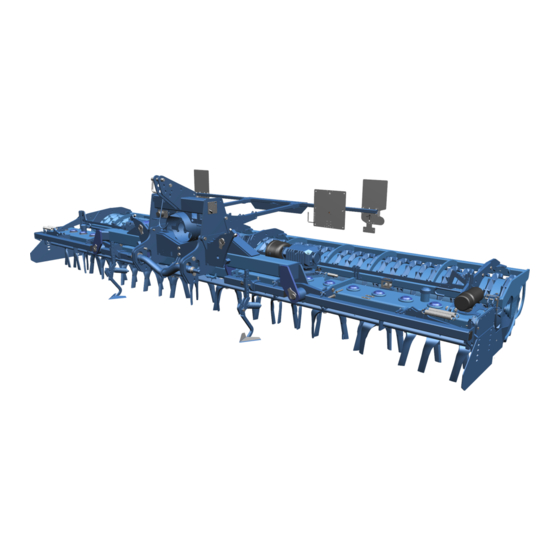
Design and description Design and description Machine overview INFORMATION The machines can be equipped differently at the factory. – Standard components, special equipment or optional accessories are not marked separately. – Contents in this document may differ from the actual equipment of the machine. - Page 25 Design and description Type plate The machine is marked with a type plate. The machine type can be identified uniquely by the type plate. Further information about the type plate: Ä Appendix A ‘Type plate variants’ on page 115 Tools and rollers The wheelmark eradicators are placed in front of the tines for lev‐...
- Page 26 Design and description Centre gearbox Manual gearbox Rear PTO (1 3/4" 6-part) Switch lever PTO shaft The machine can be equipped with one of the following centre gear‐ boxes Angular gearbox Two-speed gearbox with switch lever Above a working width of five metres, the centre gearbox is equipped with a fan in the safety shield of the PTO shaft The centre gearbox can be equipped with an electric gear oil cooler The gear oil circulates through the pump...
- Page 27 Opti‐ Disc. Coupling parts for mounting the LEMKEN Drillmaschine Solitair The machine can be equipped with coupling parts for mounting the Catch hook LEMKEN Drillmaschine Solitair. Support plates...
-
Page 28: Machine Safety
Design and description Machine safety 3.2.1 Position of the label Zirkon 12 K - Overview of safety symbols, warning stickers and other symbols 3.2.2 Meaning of the labels This section explains the information and warning signs that have been affixed to the machine. - Page 29 Design and description Reading the operating instructions Incorrect use or operation of the machine can result in death or serious injury. Before commissioning: Read and observe the operating instructions. ► Follow the instructions for action. ► Turn off the engine A tractor with the engine running can cause unintentional movements.
- Page 30 Design and description Direction of rotation of the rear PTO Clockwise direction of rotation of the rear PTO Observe the direction of rotation of the rear PTO. ► Hot surfaces Risk of burns! When working in the vicinity of hot surfaces: Keep a safe distance.
- Page 31 Design and description Area between the tractor and machine A tractor with the engine running can make or cause unintentional movements. This will result in death or serious injury. When the tractor is running: Do NOT remain in the area between the tractor and machine. ►...
- Page 32 Design and description Rotor RPM Information on gearbox, rotor RPM and cardan shaft Depth adjustment Depth adjustment scale en-GB | Item no. 17516804 | BA 00/2022-10...
-
Page 33: Safety Devices
Design and description 3.2.3 Safety devices 3.2.3.1 Lighting equipment and identification The marking and the lighting equipment increase safety while driving on the road. For public road traffic, the machine must be equipped with the fol‐ lowing components in accordance with national regulations: Marking Lighting equipment Front marking... - Page 34 Design and description Rear lighting equipment Warning board Lateral reflectors LED lighting equipment Reflector (triangle) Reflector (round) (not shown) Rear lighting equipment Example of rear lighting equipment LED indicator Reflecting film - red Reflecting film - orange LED rear light Warning board Depending on national regulations, a warning board may be required for slow-moving vehicles.
-
Page 35: Working Tools
Design and description 3.2.3.2 Safety chain For machines without a braking system, a safety chain may be required, depending on the national regulations. ATTENTION – Use the safety chain only as a safety device. Working tools Designation Properties Function and application area Blade tines SG 30 Screwed... -
Page 36: Rollers
Design and description Designation Properties Function and application area Shares G 25 Duck-foot share Wheelmark eradicator even for wide tracks Automatic overload safety device Narrow share Wheelmark eradicator for heavy, sticky soils Automatic overload safety device Large clods are not lifted to the surface. Levelling bar Levelling bar Installed at front and/or rear to the... - Page 37 Design and description Roller Light soils Crumbling Drive Reconsoli‐ Depth Levelling Resistance Resistance Row pre‐ dation control to stones to sticking consolida‐ tion Trapeze packer roller TPW 500 Trapeze packer roller TPW 600 Trapeze disc roller TSW 500 ++ = optimum + = well suited o = less well suited Roller...
-
Page 38: Commissioning
Scope of delivery and equipment of the machine may vary depending on the configuration of the purchase order. 1. Make certain that all LEMKEN original parts are present according to the purchase order. 2. Make certain that all parts are undamaged and correctly mounted (see corresponding mounting instructions if applicable). -
Page 39: Cardan Shaft
Commissioning Checklist Electrical connections Ä Electrical connections, page 106 Ä Elec‐ trical connections, page 106 An electrical connection must be available on the tractor for each consumer. Hydraulic connections Ä Hydraulic connections, page 107 Ä Hydraulic connections, page 107 A hydraulic connection and a suitable control unit must be avail‐ able for each consumer. - Page 40 Commissioning Using cardan shaft Only cardan shafts specified by the manufacturer may be used. The protection tube of the cardan shaft and the PTO guard, on both the machine and the tractor, must be in place and in good condition. In case of cardan shafts, ensure that the specified tube coverings are in the transport position and the working position.
- Page 41 Commissioning 4.1.3.1 Changing distance of the machine to the tractor Adjust the distance of the machine to the tractor by moving the cross Cross shaft shaft accordingly. INFORMATION The cross shaft can be mounted to the headstock in either of the two distance positions 4.1.3.2 Checking and shortening cardan shaft Precondition:...
- Page 42 Commissioning 4.1.3.3 RPM monitoring RPM monitoring takes place via the control element 1. Connect the connecting cable of the control element to the 3-pole DIN socket of the tractor. Control element 2. Connect the distributor for the sensors to the control ele‐ Connecting cable Distributors ment...
-
Page 43: Preparing Braking System
Commissioning Sensors S1 S2 Sensor S3 INFORMATION The speed of one or two cardan shafts is detected via the sensors S1 / S2 The sensors S1 / S2 are each located on a cardan shaft. The sensor S3 is located on the lifting device of the power harrow. -
Page 44: Attaching The Machine
Commissioning Attaching the machine Initial commissioning These operating instructions do not describe initial commissioning. INFORMATION Prior to operation, initial commissioning and instruction in operation, setting and maintenance must have been carried out by the dealer. Preparing tractor and machine 1. Clean all hydraulic connections and hydraulic plugs on the tractor and the machine. - Page 45 Commissioning ATTENTION If the pressure load on the rollers is too high and the rollers thus become clogged or sink into the ground too much, damage to the machine is possible. Reduce the weight load on the rollers: – Mount the top link higher on the headstock. INFORMATION If the pressure load is too low and the reconsolidation or crumbling effect of the rollers is insufficient, an unsat‐...
- Page 46 Commissioning Mounting machine CAUTION NEVER operate the machine without a roller or mounted on combination machine. Preconditions: √ Cross shaft is mounted in the correct position. √ Top link is mounted in the correct position. Ä ‘Changing top link mounting position’ on page 38 1.
- Page 47 1. Screw the coupling parts as shown in the figure onto the headstock of the power harrow. 2. LEMKEN Drillmaschine Solitair Mount it as follows onto the power harrow: LEMKEN Drillmaschine Solitair Secure it with the catch hook...
- Page 48 Commissioning Preparing for driving 1. Lift the machine at the front and rear. 2. Lock the control unit lever at the tractor to prevent unintentional lowering of the machine. 3. Fold in the stand. 4. Fold in the lateral sections. Ä...
-
Page 49: Attaching A Combination Machine
Commissioning 4.2.1 Attaching a combination machine Adjusting hydraulic three-point linkage Precondition: √ The catch hooks are connected to the three-point linkage. 1. Remove the screws 2. Move the catch hook to the desired position without changing the position of the lift limiter 3. - Page 50 Commissioning Mounting combination machine Top link Catch hook INFORMATION A hydraulic three-point linkage with top link and catch hook is required for the combination with a seed drill or coulter bar. 1. Dismantle the locking plates at the catch hooks 2.
- Page 51 Commissioning When working with a lift limiter 1. Close the shut-off valves 2. Lower the combination machine once via the control unit and lift it again. Shut-off valves When working in the float position 1. Open the lift limiter prior to working in the float position. 2.
- Page 52 Commissioning For transport 1. Use the control unit to adjust the combination machine to the appropriate height. 2. Close the shut-off valves 3. Deactivate the float position. 4. Move the tractor control unit to the centre position. Shut-off valves Lowering combination machine 1.
- Page 53 Stop the stop. 5. Adjust the lowering depth with the depth limiter. 6. Observe the further steps: Ä ‘Mounting a LEMKEN Drillmaschine Solitair’ on page 41 Adjusting lowering depth The lowering depth of the hydraulic three-point linkage for the coulter bar is set with the lift limiter.
-
Page 54: Checking Machine
Commissioning Checking machine Safety guards To ensure safe operation, the existing safety guards must always remain on the machine. With levelling bar and roller Roller Roller Levelling bar Protection tube ► Without levelling bar: Mount the additional protection tube After initial commissioning After initial commissioning, at the latest after 2 hours of use: Retighten all screws and nuts on the machine to the appropriate ►... - Page 55 Commissioning At the latest after the first 50 hours of use: Change oil in the manual gearbox. ► Ä Chapter 9.2.5 ‘Hydraulics and gearbox’ on page 86 en-GB | Item no. 17516804 | BA 00/2022-10...
-
Page 56: Road Travel
Ä ‘Preparing tractor and machine’ on page 38 Ä ‘Changing top link mounting position’ on page 38 Ä ‘Mounting machine’ on page 40 Ä ‘Mounting a LEMKEN Drillmaschine Solitair’ on page 41 Ä ‘Preparing for driving’ on page 42 Ä ‘Adjusting hydraulic three-point linkage’ on page 43 Ä ‘Mounting combination machine’... - Page 57 Road travel Checklist Securing of the lateral Folding machine is folded in and secured. sections in transport Ä Chapter 6.1.1 ‘Folding machine’ on page 56 position Stop screws Stop screws are adjusted. Ä Chapter 5.2.3 ‘Adjusting stop screws’ on page 54 Lateral safety guards Lateral safety guards are mounted.
-
Page 58: Preparing The Lighting Equipment For Road Travel
Road travel Checklist Arm of the track marker is folded in The folded in arm of the track marker hydraulically. is secured with a pin. Transport dimensions Maximum permitted transport dimensions are met: – Transport width 3 m* – Transport height 4 m Ä... - Page 59 Road travel Upper coupling points Lower coupling points To ensure correct mounting of the additional trailer, the lower coupling point can be adjusted precisely for mounting the power harrow via the adjusting screws Adjusting screw Mounting additional trailer 1. Dismantle the lever .
-
Page 60: Adjusting Stop Screws
Road travel 6. Slowly lift the power harrow until the additional trailer engages at the lower coupling point 7. Continue to lift the power harrow until the additional trailer is no longer in contact with the ground. 8. Secure the machine against unintentional lowering. Upper coupling point 9. - Page 61 Road travel Stop screw 3. Make sure the locking devices have engaged. Lock nut Locking devices en-GB | Item no. 17516804 | BA 00/2022-10...
-
Page 62: Operation
Operation Operation Basic operation 6.1.1 Folding machine Folding machine out Preconditions: √ NO overhead lines in the folding range √ NO persons in the folding range √ Tractor has stopped. √ Machine is lifted fully at the front and rear. 1. - Page 63 Operation 4. Lock the tractor control unit for the folding cylinders. ð Machine is folded in. 5. When the machine is folded in for driving on public roads: Lower the machine slightly. Maximum transport height of 4 m is observed. ð...
-
Page 64: Changing The Setup State
Operation Changing the setup state 6.2.1 Changing blade tines 1. Turn off the engine. 2. Engage the parking brake of the tractor. 3. Remove the ignition key. 4. Secure the tractor-machine combination to prevent it from rolling away. 5. When working on folding machines: Fold out the folding parts of the machines or secure them against folding out. - Page 65 Operation 2. Remove the locking device. ATTENTION: The locking device locks both blade tines of a rotor. – Make sure the other blade tine does not fall out. 3. Pull the blade tines out of the tine carrier. 4. Insert new blade tines into the tine carrier. 5.
- Page 66 Operation 7. Use a size 24 open-end wrench to rotate the locking device 90°. ð The blade tines have been changed. Screwed The tines can be mounted in the drag or the grip position. Changing from the drag to the grip position can be performed, e.g., when changing tines.
-
Page 67: Adjusting The Machine
Operation 2. Mount new blade tines. 3. Tighten all the screws to a tightening torque of 450 Nm. 4. Make sure all the blade tines have been mounted correctly: Turn the rotors manually. – Possible without problems: All the blade tines have been mounted correctly. - Page 68 Operation Mechanical setting Spring pin Each power harrow unit has a central depth adjustment Adjusting rod Depth adjustment Centre of machine outside 1. Lift the machine. 2. Remove the spring pin 3. Move the adjusting rod Impact on the working Move the adjusting rod depth ...towards the centre of the...
- Page 69 Operation Hydraulic adjustment INFORMATION Hydraulic adjustment is not possible in combination with a seed drill. 1. Lift the machine. 2. Adjust the working depth of the hydraulic rams using the control unit of the tractor. ð The working depth has been adjusted hydraulically. 6.3.1.1 Adjusting levelling bar Preconditions:...
- Page 70 Operation 6.3.1.2 Adjusting feed discs Relocation at the side 1. Undo the screws 2. Slide the feed disc onto the carrier at the required working width. 3. Tighten the screws to 197 Nm. 4. Unlock the pin 5. Adjust the required working depth by altering the position of the 6.
- Page 71 Operation 6.3.1.3 Adjusting wheelmark eradicators Wheelmark eradicators can be mounted on the carrier. The wheelmark eradicators can be displaced laterally and their depth adjusted. Working depth INFORMATION Adjust the wheelmark eradicators approx. 5 cm lower than the tracks left by the tractor. 1.
- Page 72 Operation 1. Undo the screws 2. Adjustment dimensions can be found in the following table: Screws Track marker arm Zirkon 12 K Distance from middle Distance from the outer seeding coulter Track marker disc of seed drill to track [cm]...
-
Page 73: Rotors And Gearbox
Operation Shear bolt 6.3.2 Rotors and gearbox 1. Turn off the engine. 2. Engage the parking brake of the tractor. 3. Remove the ignition key. 4. Secure the tractor-machine combination to prevent it from rolling away. 5. When working on folding machines: Fold out the folding parts of the machines or secure them against folding out. - Page 74 Operation 2. Carefully clean the area surrounding the gearbox flange at the side gearbox Side gearbox 3. Remove the protecting caps Gearbox flange Protecting caps 4. Undo the centring nuts until the centring nuts are flush with the Turnbuckle stud bolt 5.
- Page 75 Operation 6.3.2.2 Setting gearbox The machine can be equipped with one of the following centre gear‐ Manual gearbox Rear PTO (1 3/4" 6-part) boxes Switch lever Angular gearbox PTO shaft Two-speed gearbox with switch lever At the angular gearbox (basic equipment), the speed is set to 330 rotor RPM with the 1000 rpm PTO shaft or optionally to 440 rotor RPM.
-
Page 76: Adjusting Side Shields
Operation 6.3.3 Adjusting side shields 1. Turn off the engine. 2. Engage the parking brake of the tractor. 3. Remove the ignition key. 4. Secure the tractor-machine combination to prevent it from rolling away. 5. When working on folding machines: Fold out the folding parts of the machines or secure them against folding out. -
Page 77: Adjusting Rollers
Operation 6.3.4 Adjusting rollers 1. Turn off the engine. 2. Engage the parking brake of the tractor. 3. Remove the ignition key. 4. Secure the tractor-machine combination to prevent it from rolling away. 5. When working on folding machines: Fold out the folding parts of the machines or secure them against folding out. - Page 78 Operation 1. Remove the screw 2. Undo the screw , thus allowing it to move in the slot. 3. Pull the roller to the rear in the slot. 4. Retighten the screw ATTENTION: Observe tightening torques. 5. Fit the screw 6.
-
Page 79: Working With The Machine
Operation Working with the machine 6.4.1 Standard procedure Dismantling additional trailer An additional trailer can be connected to the power harrow at two axles: Upper coupling points Lower coupling points 1. Hook in the top link. 2. Slowly lift the power harrow until the additional trailer is no longer in contact with the ground. - Page 80 Operation Machine operation CAUTION Risk of injury due to foreign objects being ejected During work, there is a risk of injury to your face and body by lumps of earth, soil constituents or stones being ejected at high speed. – During operation, no persons may be present directly in front of, behind or next to the machine.
-
Page 81: Driving On The Headland
Operation 10. Do not reinsert the machine until driving straight forward. 11. On completion of soil cultivation: Clean the machine and remove coarse dirt. 12. Prepare the machine for road travel. 6.4.2 Driving on the headland 1. Before the headland: Lift the machine fully. -
Page 82: Cleaning And Care
Cleaning and care Cleaning and care Cleaning with a high-pressure cleaner ATTENTION Material damage due to cleaning with a hot water high-pressure cleaner Hydraulic components may be damaged when cleaning with a hot water high-pressure cleaner. – NEVER clean the machine with a hot water high-pres‐ sure cleaner during the first 6 weeks. -
Page 83: Detaching Machine
Detaching machine Detaching machine Detaching machine 1. If the machine is to be parked in the folded in position: Fold in the machine: Ä Chapter 6.1.1 ‘Folding machine’ on page 56 To ensure that the lateral parts are held in the folded in posi‐ tion when the machine is already folded in: –... - Page 84 Detaching machine √ The subsoil is level with sufficient bearing capacity. √ When used in conjunction with the hydraulic three-point linkage and the mounted seed drill, the hydraulic three-point linkage and the seed drill must be lowered fully before detaching the power harrow.
-
Page 85: Storing And Wintering Machine
Detaching machine 9. Detach the top link on the machine. Top link tractor 10. Swivel down the holder of the cardan shaft. Cardan shaft Cardan shaft guard on the machine 11. Dismantle the cardan shaft on the tractor. 12. Place the cardan shaft into the holder . 13. -
Page 86: Maintenance And Repair Work
Maintenance and repair work Maintenance and repair work Maintaining the machine properly Personnel Certain activities, e.g. working on hydraulic hoses, should only be car‐ ried out by service personnel. These tasks are: Highlighted with the symbol Marked in the SERVICE PERSONNEL column in the maintenance schedule. -
Page 87: During The Maintenance And Repair
Maintenance and repair work 9.1.2 During the maintenance and repair To prevent accidents or injuries: Wear protective equipment. ► Use auxiliary equipment, e.g.: ► Suitable tools Climbing aids Supporting elements For dismantling and mounting heavy components: ► Use hoisting gear. Check nuts and screw heads etc. - Page 88 Maintenance and repair work Chap. Task to execute 9.2.3.2 Checking attachment of the retaining ● bolts 9.2.4 Checking the lighting equipment ● 9.2.4 Check the hydraulic transport locking ● device 9.2.4 Check marking ● 9.2.4 Checking safety sticker ● 9.2.5.1 Checking hydraulic hoses ●...
-
Page 89: Checking Cardan Shaft
Maintenance and repair work 9.2.2 Checking cardan shaft 1. Make sure that the cardan shaft can be pushed in and pushed out easily. 2. Make sure that the cardan shaft protection tubes are secure and fully functional. Replace defective cardan shafts or have them repaired by service ►... - Page 90 Maintenance and repair work 9.2.3.2 Bolted connections Checking the bolted connections Bolted connections on which adjustments have been made: 1. Check and retighten the bolted connections. 2. If necessary, secure the bolted connections with locking com‐ pound. Checking bolted connections Bolted connections at moving parts or parts subject to a high load: 1.
-
Page 91: Checking Safety Devices
Maintenance and repair work Checking attachment of the retaining ATTENTION bolts Loose retaining bolts Attachment of the retaining bolts is subject to natural settling properties. – Retighten the retaining bolts after the first 10 oper‐ ating hours. 1. Check correct attachment of the retaining bolts: Tightness Position of the retaining bolts Correct: centre position... -
Page 92: Hydraulics And Gearbox
Maintenance and repair work Check the hydraulic transport locking device Ensure proper functioning. ► Check marking Ensure proper functioning. ► Checking safety sticker Ensure legibility and integrity. ► 9.2.5 Hydraulics and gearbox 9.2.5.1 Hydraulics Checking hydraulic hoses 1. Check hydraulic hoses for damage and leakages. Replace damaged or defective hydraulic hoses immedi‐... -
Page 93: Checking Hydraulic Connections
Maintenance and repair work Checking hydraulic connections 1. Check the hydraulic connections for the following when pressure‐ less: Damage Leakages Repair damaged or leaking hydraulic connections imme‐ ð diately or have them replaced. 2. Connect the hydraulic connections pressureless. 3. Check leak tightness of the hydraulic connections under pressure. ð... -
Page 94: Checking Fluid Grease In The Trough
Observe fluid grease quantities (item number 877 1595): Zirkon 12 K 400 = 22 l for each power harrow unit (44 l in total) Zirkon 12 K 450 = 25 l for each power harrow unit (50 l in total) -
Page 95: Checking Trough Breathers
Maintenance and repair work Checking trough breathers The trough breathers ensure pressure equalisation in case of increased internal trough pressure. Make sure the breathers are unblocked and clean. ► Checking fans of the centre gearbox ► In case of soiling, clean the space between the fan and the safety shield... -
Page 96: Checking Oil Level In The Manual Gearbox
Maintenance and repair work Checking oil level in the manual gearbox Preconditions: √ Machine is folded out and standing on a level and horizontal sur‐ face. √ The PTO shaft and the tractor engine are switched off. √ Ignition key has been removed. Manual gearbox and centre angular gearbox Control screw... -
Page 97: Replacing Oil In The Manual Gearbox
Maintenance and repair work Replacing oil in the manual gearbox √ Replace oil for the first time after the first 50 operating hours. √ Then always replace oil after each 200 hours of operation, at the latest after 500 operating hours, and at least once a year. ATTENTION –... -
Page 98: Electrics
Maintenance and repair work Checking rotor bearings Precondition: √ Machine has been running for less than 1000 operating hours Check the rotor bearings for play to prevent any damage to the ► gear wheels and the trough. Precondition: √ Machine has been running for more than 1000 operating hours Check the rotor bearings for play to prevent any damage to the ►... -
Page 99: Rollers
Maintenance and repair work 9.2.8 Rollers 9.2.8.1 Checking roller scraper Precondition: √ Only required for rollers with scrapers, e.g. trapeze roller, packer roller or trapeze packer roller. 1. Check the distance between the scraper and the roll sleeve Turn the roller through 360°. INFORMATION: The scraper must not touch the roll sleeve at any position. -
Page 100: Lubricating
Maintenance and repair work Lubricating 9.3.1 Lubrication schedule INFORMATION The lubrication points are colour coded on the machine. Chap. Task to execute 9.3.2 Lubricating track marker disc bearings ● ● ● 9.3.2 Lubricating track marker arm ● ● ● 9.3.2 Lubricating feed disc ●... -
Page 101: Lubricating Components Via Grease Nipples
Maintenance and repair work 9.3.2 Lubricating components via grease nipples Lubricating track marker disc bear‐ ings Lubricate the lubricating point at the track marker. ► Lubricating track marker arm Lubricate 2 lubricating points at the track marker arm. ► en-GB | Item no. 17516804 | BA 00/2022-10... -
Page 102: Lubricating Feed Disc
Maintenance and repair work Lubricating feed disc Lubricate the lubricating point at each feed disc. ► Lubricating hydraulic three-point linkage 1. Lubricate 4 lubricating points at the hydraulic three-point linkage. 2. Lubricate 2 lubricating points of the lifting arms at the hydraulic three-point linkage. -
Page 103: Lubricating Folding Joints
Maintenance and repair work Lubricating folding joints Lubricate the lubricating point at each folding joint. ► Lubricating cylinder folding Lubricate the lubricating point at folding cylinder. ► Lubricating beam Lubricate the lubricating point at each beam. ► en-GB | Item no. 17516804 | BA 00/2022-10... -
Page 104: Lubricating Additional Trailer
Maintenance and repair work Lubricating additional trailer Lubricate 2 lubricating points at the additional trailer. ► Lubricating hydraulic rams Lubricate 2 lubricating points at each hydraulic ram . ► Lubricate wheel bearing ► Lubricate 1 lubricating point at the wheel bearing Wheel bearing lubricating point Lubricating cardan shaft Lubricate the cardan shaft according to the instructions of the... -
Page 105: Grease Components
Maintenance and repair work 9.3.3 Grease components Grease top link pin Dismantle, grease and reassemble the top link pin. ► Grease pin Dismantle pin, grease and reassemble. ► Grease piston rods Grease piston rods with an acid-free grease. ► Grease surfaces Grease uncoated surfaces that can rust. -
Page 106: 10 Troubleshooting And Error Correction
Troubleshooting and error correction 10 Troubleshooting and error correction 10.1 Finding and eliminating errors correctly 10.1.1 Before troubleshooting on the machine 1. Park the tractor/machine combination. 2. Secure the tractor/machine combination to prevent it from rolling away. 3. When working on folding machines: Fold out the folding parts of the machines or secure them against folding out. -
Page 107: Error - Cause - Remedies At A Glance
Troubleshooting and error correction 10.2 Error - Cause - Remedies at a glance 1. Turn off the engine. 2. Engage the parking brake of the tractor. 3. Remove the ignition key. 4. Secure the tractor-machine combination to prevent it from rolling away. - Page 108 Troubleshooting and error correction Fault description Cause Remedy Set the flow rate to maximum flow at the control valve. Machine does not fold Transport locking device out. still engaged. en-GB | Item no. 17516804 | BA 00/2022-10...
-
Page 109: Shutdown And Disposal
Shutdown and disposal 11 Shutdown and disposal 11.1 Shutdown When the machine can no longer be used, it is dismantled and broken down into its components. Special knowledge is required to dismantle the machine. CAUTION Risk of accidents due to discharge of stored energy Springs are under tension. -
Page 110: Technical Data
Technical data 12 Technical data 12.1 Dimensions Zirkon 12 K Working width , approx. [cm] Rotors Number To determine the actual dimensions: Measure the machine. 12.2 Machine weights Zirkon 12 K Total weight , approx. 1762 1896 2066 2452 Total weight incl. Toothed... - Page 111 Technical data Operating speed and gearbox setting Recommended operating speed depending on rotor RPM Rotor RPM Operating speed 1. gear 2. gear Gearbox Rotor RPM Translation / [rpm] gear 1000 Standard Angular gearbox Optional Two-speed manual gearbox en-GB | Item no. 17516804 | BA 00/2022-10...
-
Page 112: Connection Data
Zirkon 12 K - Angular gearbox [HP] 120...270 135...270 165...300 180...320 Engine power, , min‐ imum...maximum [kW] 88...199 99...199 121...221 132...235 Zirkon 12 K - Two-speed manual gearbox [HP] 120...360 135...360 165...390 180...408 Engine power, , min‐ imum...maximum [kW] 88...265 99...265 121...287 132...300 12.5... -
Page 113: Hydraulic Connections
LS = load-sensing 12.6 Noise, airborne sound £70 dB(A) Noise level of the machine while working 12.7 Operating materials Zirkon 12 K Hydraulic oil [l] For each power harrow Fluid grease trough [l] unit Part number 877 1595 Whole machine... -
Page 114: Tyres And Wheels
Tyre designation Function [bar] 340/55-16TL 140 A8 Additional trailer OptiDisc 12.9 Connecting systems at the machine Permitted categories - Cross shaft and Top link pin Zirkon 12 K Cross shaft Category 3 ● ● ● ● Cross shaft Category 4N ●... -
Page 115: Index
Airborne sound ......107 LEMKEN Drillmaschine Solitair ... . . 21 Ambient conditions . - Page 116 Meaning ......22 LEMKEN Drillmaschine Solitair Setting ......20, 69 Coupling parts .
- Page 117 Repair work ......80 LEMKEN Drillmaschine Solitair ... . . 41 Retaining bolts Check attachment .
- Page 118 Index Roller Technical data ......104 Check scraper ......93 Connecting systems .
- Page 119 Index Tyres/Wheels ......108 Unhitching - machine from tractor ... . 77 Validity range .
-
Page 120: Appendix
Appendix Appendix en-GB | Item no. 17516804 | BA 00/2022-10... -
Page 121: A Type Plate Variants
Type plate variants Type plate variants Series 11 Permissible axle load [kg] (axle 1) Type designation 12 Permissible axle load [kg] (axle 2) Model year 13 CE label Serial number 14 EAC label Year of manufacture 15 Company name and address of the manufacturer Vehicle class, subclass, speed index 15a Address of the manufacturer EU type approval number... - Page 122 Type plate variants en-GB | Item no. 17516804 | BA 00/2022-10...
-
Page 123: B Tightening Torques Screws
Tightening torques screws Tightening torques screws Bolted connections, general principles The following tightening torques refer to screw connections not spe‐ cifically mentioned in these mounting instructions. Special tightening torques are indicated in the text. Identify screw connection: – Identification on the screw head –... - Page 124 The friction coefficient of 0.14 ... 0.15 must be complied with. Never tighten with an impact wrench Tightening torques for bolted connections The following tightening torques apply with all bolted connections used by LEMKEN, unless specified otherwise: Screws and nuts made of steel Diameter Strength category 8.8 [Nm*]...
- Page 125 Tightening torques screws Diameter Strength category 8.8 [Nm*] 10.9 [Nm*] 12.9 [Nm*] 1245 1450 1121 1570 1892 1958 2753 3304 * µ = 0.09 Diameter Strength category 8.8 [Nm*] 10.9 [Nm*] 12.9 [Nm*] M8 x 1 22.8 32.0 38.4 M10 x 1 40.9 57.5 68.9...
- Page 126 Tightening torques screws Screws and nuts made of stainless steel Diameter [Nm*] A2-70 A4-80 11.5 19.0 25.5 38.0 51.0 65.0 87.0 * µ = 0.14 Tightening torques for wheel bolts and wheel nuts Implements Diameter / thread [Nm] Every M14 x 1,5 Every M18 x 1,5 Every...
- Page 127 The tightening torques are calculated for the friction values µ specified in the tables. The required tightening torque deviates: – If any screws other than LEMKEN original screws are used. – If screws are re-used. Only use LEMKEN original screws!
-
Page 128: C Calculation Of Axle Load And Ballasting For Mounted Machines
Calculation of axle load and ballasting for mounted machines Calculation of axle load and ballasting for mounted machines The calculation of the axle loads and required ballasting is based on data from the operating instructions for the tractor and machine. The result of the calculation is a guide value for an initial assessment of the axle loads and the required ballasting. - Page 129 Calculation of axle load and ballasting for mounted machines Data acquisition for calculating axle loads Abbreviation Description Value Unit Tractor data from the operating instructions or determined by weighing Permissible gross weight of the tractor [kg] G_zul Permissible front axle load [kg] V_zul Permissible back axle load...
- Page 130 Calculation of axle load and ballasting for mounted machines Minimum ballasting, FrontG Vmin rear-mounted machine Enter the calculated value in the result table. Minimum ballasting, RearG Hmin front mounted machine Enter the calculated value in the result table. Actual gross weight G Enter the calculated value in the result table.
- Page 131 Calculation of axle load and ballasting for mounted machines Results for tractor/implement combination Create a result table for each tractor that is used: Actual value Permitted value Double permis‐ according to calculation according to tractor sible tyre load- or measurement operating instruc‐...
-
Page 132: D Cross Shaft Overview
Cross shaft overview Cross shaft overview To determine the cross shaft or lower link connection: Determine the dimensions shown in the sketch on the machine. Compare the dimensions with the data in the table. The category of the three-point linkage must match with the cate‐ gory of cross shaft or lower link connection. - Page 134 LEMKEN GmbH & Co. KG Weseler Strasse 5 D-46519 Alpen Telephone: +49 2802 81-0 Fax: +49 2802 81-220 Email: info@lemken.com Internet: www.lemken.com...
Need help?
Do you have a question about the ZIRKON 12 K and is the answer not in the manual?
Questions and answers