
Related Manuals for Dyness B3


Summary of Contents for Dyness B3
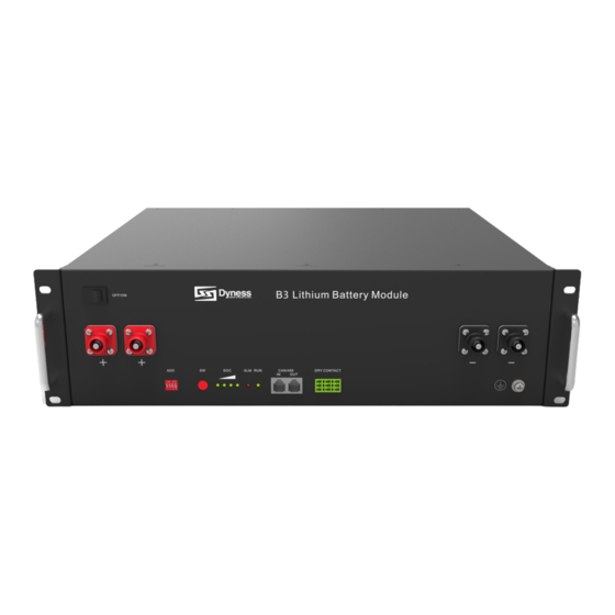
- Page 1 USER MANUAL Battery Module 48V/75Ah File version-20231114-V2-EN Information might be subject to change without notice during product improving.
-
Page 2: Table Of Contents
B3 ESS Unit User Manual Contents Statement of Law ..........................1 Revision History ............................1 Safety Precautions ........................2 Preface ............................. 3 Manual declaration .............................3 1 Introduction ..........................4 Brief Introduction ............................4 Product Properties ............................4 Product identity definition ........................5 2 Product Specification ......................6 Size and Weight ............................6... -
Page 3: Statement Of Law
The storage, use and disposal of the products shall be carried out in accordance with the product manual, relevant contract or relevant laws and regulations. Customer can check the related information on the website of Dyness Digital Energy Technology Co., LTD. when the product or technology is updated. -
Page 4: Safety Precautions
Please charge the battery in 18 hours after it fully discharged or over-discharging protection mode is activated. Formula of theoretical standby time: T=C/I (T is standby time, C is battery capacity, I is total current of all loads). ©Dyness reserves the copyright of this document. -
Page 5: Preface
B3 ESS Unit User Manual Preface Manual declaration B3 lithium iron phosphate battery energy storage system can provide energy storage for photovoltaic power generation users through parallel combination. Our product can store extra electricity into battery from photovoltaic power generation system in daytime and supply stable power to user’s equipment as power backup at nighttime or any time when... -
Page 6: Introduction
B3 lithium iron phosphate battery system is a standard battery system unit, customers can choose a certain number of B3 according to their needs, by connecting parallel to form a larger capacity battery pack, to meet the user's long-term power supply needs. -
Page 7: Product Identity Definition
This battery product meets European directive requirements. This battery product passed the TUV certification test. Dangerous goods warning label on the top of the battery module ©Dyness reserves the copyright of this document. -
Page 8: Product Specification
2.64 1S Peak Current(A) Charging Current(A) 37.5 Discharge Current(A) 37.5 Interface Definition This section elaborates the interface functions of the front interface of the device. 7 8 9 Figure 2-1The sketch of interface. ©Dyness reserves the copyright of this document. - Page 9 Table 2-4 Interface Definition DIP switch position (master communication protocol and baud rate selection) Baud rate selection Define different protocols; Distinguish between OFF:CAN: 500K,485: 9600 master and slave ON:CAN: 250K,485: 115200 DIP switch description: © Dyness reserves the copyright of this document.
- Page 10 CAN or 485 If the master is the latest B3 battery with DIP switch: 1. The communication cable from the master CAN IN to the inverter comm port should be the correct one.
- Page 11 5. Slave Setting 2 8. If the energy storage system has only one B3, it is the master itself, and still follow the above steps. Note: For more information of matching inverter brands, please subject to the latest document <The list of compatibility between Dyness ESS and Inverters >.
- Page 12 PIN6 Green Reserve PIN7 Brown/white PIN8 Brown Reserve PIN9 Orange/white Reserve PIN10 Orange XGND PIN11 Green/white Reserve PIN12 Blue CANH PIN13 Blue/white CANL PIN14 Green Reserve PIN15 Brown/white XOUT PIN16 Brown Reserve © Dyness reserves the copyright of this document.
-
Page 13: Battery Management System(Bms)
When any battery cell voltage or total voltage is lower than the rated protection value during discharging, the over-discharging protection is activated, and the battery buzzer makes an alarm sound. Then battery system stops supplying power to the outside. When ©Dyness reserves the copyright of this document. - Page 14 60 seconds. Self-Shutdown: CAUTION Battery’s maximum discharging current should be more than load’s maximum working current. When device connects no external loads and power supply and no external © Dyness reserves the copyright of this document.
- Page 15 B3 ESS Unit User Manual communication for over 72 hours, device will dormant standby automaticall. © Dyness reserves the copyright of this document.
-
Page 16: Installation And Configuration
Installation location should be away from the sea to avoid brine and high humidity environment. The ground for product arrangement shall be flat and level. There is no flammable explosive materials near to the installation site. The optimal ambient temperature is 15 C~30 © Dyness reserves the copyright of this document. - Page 17 Table 2-2, the DC power interface of the user's photovoltaic power generation equipment shall have a current limiting function to ensure the normal operation of the user’s equipment. © Dyness reserves the copyright of this document.
- Page 18 Specification Quantity Figure 48V/75Ah Battery-B3 480×360×130mm Optional:If you need,Please Power cable- Red/25mm /L2050m contact the positive dealer to purchase Optional:If you need,Please Power cable- Black/25mm /L2050m contact the negative dealer to purchase © Dyness reserves the copyright of this document.
-
Page 19: Equipment Installation
Make sure that the battery has enough room to install, and that the battery rack and bracket have enough load capacity. Wiring. Make sure the power line and ground wire are reasonable. Not easy to short-circuit, water and corrosion. Equipment installation © Dyness reserves the copyright of this document. - Page 20 B3 ESS Unit User Manual Step1 Installation preparation Confirm that the ON/OFF switch on the front panel of B3 unit is in the “OFF” state to ensure no live operation. Step 2 Mechanical installation 1. Battery placement position determination 2. Battery module installation Step 3 Electrical installation 1.
- Page 21 Mechanical installation Installation method 1:With fixed rack 1. Place the B3 unit on the bracket as shown in the figure and push the device into the cabinet at the installation position. (The cabinet structure in the figure is for reference...
- Page 22 B3 ESS Unit User Manual 1.Place the B3 and brackets as shown in the figure3-5, and insert the B3 into the brackets.Use 4 screws to fix the module on the front bracket. Figure 3-5 2. Install another pair of bracket on the first one,fixed by buckles between them.
- Page 23 It is better to add a circuit breaker between the inverter and the battery system. The selection of the circuit breaker requires: Voltage: U>60V Current: I = Inverter power/45V The circuit breaker is installed between the battery module and the inverter, as shown in Figure 3-9: © Dyness reserves the copyright of this document.
- Page 24 CAN OUT to slave1 CAN IN,slave1 CAN OUT to slave2 CAN IN… Each pair of power cable,it’s limited continuous current is 120A,so if the inverter Max.work current more than 120A,please add power cable according to the proportion. © Dyness reserves the copyright of this document.
-
Page 25: Battery Parameter Settings On The Inverter
After the battery system installation is completed and the running is normal, you need to log in to the DYNESS official website to register the product installation and use information to make the product warranty effective. Please follow the instructions on the website to register. -
Page 26: Use, Maintenance And Troubleshooting
Alarm description and processing When protection mode is activated or system failure occurred, the alarm signal will be given through the working status indicator on the front panel of the B3. The network management can query the specific alarm categories. -
Page 27: Analysis And Treatment Of Common Faults
Storage battery replacement time is too short become smaller or add more modules The battery can't be fully Charging voltage is Adjust charging voltage at charged to 100% too low 53.5V or 54V © Dyness reserves the copyright of this document. - Page 28 Analysis and treatment of common faults in the Table 4-2: Table 4-2 Analysis and treatment of common faults If you need any technical help or have any question, please contact the dealer in time. © Dyness reserves the copyright of this document.
- Page 29 Address: No. 511 Chenzhuang West Road, Sanshui Street, Jiangyan District, Taizhou City Email: service@dyness-tech.com Tel: +86 400 666 0655 Web: www.dyness.com Official Website Digital version access...
Need help?
Do you have a question about the B3 and is the answer not in the manual?
Questions and answers