
Related Manuals for Dyness DL5.0C


Summary of Contents for Dyness DL5.0C
- Page 1 DL5.0C Battery Module 51.2V/100Ah DL5.0C USER MANUAL USER MANUAL File version-20230330-V1-EN information might be subject to change without notice during product improving.
-
Page 2: Table Of Contents
Equipment Installation ......................16 4 Use, Maintenance and Troubleshooting ..............26 Battery system usage and operation instructions ........... 26 Alarm description and processing ................. 26 Analysis and treatment of common faults ..............27 © Dyness reserves the copyright of this document... -
Page 3: Statement Of Law
(Taizhou) Co., Ltd when the product or technology is updated. Web URL: http://www.dyness-tech.com/ Please note that the product can be modified without prior notice. Revision History Revision NO. Revision Date Revision Reason 2023.02.28 First Published © Dyness reserves the copyright of this document... -
Page 4: Safety Precautions
Please charge the battery in 18 hours after it fully discharged or over-discharging protection mode is activated. Formula of theoretical standby time: T=C/I (T is standby time, C is battery capacity, I is total current of all loads). © Dyness reserves the copyright of this document... -
Page 5: Preface
DL5.0C User Manual Preface Manual declaration DL5.0C lithium iron phosphate battery energy storage system can provide energy storage for photovoltaic power generation users through parallel combination. Our product can store extra electricity into battery from photovoltaic power generation system in daytime and supply stable power to user’s equipment as power backup at nighttime or any time when needed. -
Page 6: Introduction
Brief Introduction DL5.0C lithium iron phosphate battery system is a standard battery system unit, customers can choose a certain number of DL5.0C according to their needs, by connecting parallel to form a larger capacity battery pack, to meet the user's long-term power supply needs. -
Page 7: Product Identity Definition
If catch fire, do not put out with dry powder fire extinguisher. Do not cut or spear with sharp objects. This battery product meets European directive requirements. Figure 1-1 Battery Module Label © Dyness reserves the copyright of this document... -
Page 8: Product Specification
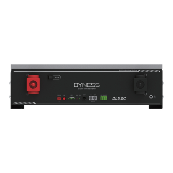
Recommend Charge Voltage (Vdc) 56.5 Interface Definition This section elaborates the interface functions of the front interface of the device. 3 4 5 6 7 8 9 The Sketch of Interface Figure 2-1 © Dyness reserves the copyright of this document... - Page 9 CAN interface. The host summarizes the information of the entire battery system and communicates with the inverter through CAN or 485. If the master is the latest DL5.0C battery with DIP switch: 1. The communication cable from the master CAN IN to the inverter comm port should be the correct one.
- Page 10 6. When you setup the master DIP as setting 1~4, all the slaves keep the DIP 0000,no need to change. 7. If the energy storage system has only one DL5.0C, it is the master itself, and still follow the above steps.
- Page 11 INT CANL PIN9 Orange/white Reserve PIN10 Orange Reserve PIN11 Green/white Reserve PIN12 Blue Reserve PIN13 Blue/white Reserve PIN14 Green Reserve PIN15 Brown/white INT CANH PIN16 Brown INT CANL Figure 2-3 COM Interface Definition © Dyness reserves the copyright of this document...
- Page 12 SOC to RUN of the master battery will flash together. ● means green light always on ● means red light always on Flashing: means green light flashing or red light flashing © Dyness reserves the copyright of this document...
-
Page 13: Battery Management System(Bms)
The protection is over when temperature back to rated working range. Other Protection Short Circuit Protection: When the battery is activated from the shutdown state, if a short circuit occurs, the system starts short-circuit protection for 60 seconds. Self-Shutdown: © Dyness reserves the copyright of this document... - Page 14 When device connects no external loads and power supply and no external communication for over 72 hours, device will dormant standby automatically. CAUTION Battery’s maximum discharging current should be more than load’s maximum working current. © Dyness reserves the copyright of this document...
-
Page 15: Installation And Configuration
The ground for product arrangement shall be flat and level. • No flammable explosive materials near the installation site. • The optimal ambient temperature is 15 C~30 • Keep away from dust and messy zones Tools and data © Dyness reserves the copyright of this document... - Page 16 Firefighting equipment should be provided near the product, such as portable dry powder fire extinguisher. • Automatic fire fighting system shall be provided for the case where necessary. • No flammable, explosive and other dangerous materials are placed beside the battery. © Dyness reserves the copyright of this document...
- Page 17 Black negative /4AWG/L250mm Black Communication /L500mm/Double parallel cable RJ45 plug Black Communication /L2000mm /Double cable-to inverter RJ45 plug L500mm,4mm² Ground wire User Manual User manual Screw Screws M6 Expansion screw Expansion screw © Dyness reserves the copyright of this document...
-
Page 18: Equipment Installation
Equipment Installation Table 3-2 Installation steps Step 1 Installation preparation Confirm that the ON/OFF switch on the front panel of DL5.0C unit is in the “OFF” state to ensure no live operation. Step 2 Mechanical installation 1. Battery placement position determination 2. - Page 19 5. Turn on the Power switch and wake up system by SW button. SW (Battery sleep switch) 6. Close the DC breaker between inverter and battery. 7. Turn on the inverter and check the communication between inverter and battery © Dyness reserves the copyright of this document...
- Page 20 Installation Preparation 1. Prepare equipment and tools for installation. 2. Check the DL5.0C unit and confirm that the ON/OFF switch is in the "OFF" state to ensure the device is shut off. Mechanical Installation Flexible Brackets Installation(Up to six layers): DL5.0C brackets The DL5.0C bracket is shown before installation as shown in...
- Page 21 9.8N·m. Shown as Figure3-7. Figure 3-7 Wall hanging Installation method: Use the positioning cardboard (provided in accessory package) and mark the screw hole positions on the wall. Shown as Figure 3-8. Figure 3-8 © Dyness reserves the copyright of this document...
- Page 22 1.Use the positioning cardboard (provided in accessory package) and mark the screw hole positions on the wall, as shown four holes in the picture on the left. © Dyness reserves the copyright of this document...
- Page 23 5.Use the M6 bolt to fixing the Support bracket to the wall and control the torque at 6NM. Figure 3-13 6.Carry the battery box to the installation site, and place it about 15mm away from the wall surface, fixing the Support bracket and the cabinet. Figure 3-14 © Dyness reserves the copyright of this document...
- Page 24 It is better to add a circuit breaker between the inverter and the battery system. The selection of the circuit breaker requires: Voltage: U>60V Current: I =Inverter power/45V The circuit breaker is installed between the battery module and the inverter, as shown in Figure 3-16: © Dyness reserves the copyright of this document...
- Page 25 DL5.0C User Manual © Dyness reserves the copyright of this document...
- Page 26 Parallel cable Master Setting 1 Master Setting 2 Master Setting 3 Master Setting 4 Slave Setting 1 Figure 3-15 Note: 1. For more ADD Settings,please refer to P7 “DIP switch definition and description” © Dyness reserves the copyright of this document...
- Page 27 After the battery system installation is completed and the running is normal, you need to log in to the DYNESS official website to register the product installation and use information to make the product warranty effective. Please follow the instructions on the website to register.
-
Page 28: Use, Maintenance And Troubleshooting
Alarm Description and Processing When protection mode is activated or system failure occurred, the alarm signal will be given through the working status indicator on the front panel of the DL5.0C. The network management can query the specific alarm categories. -
Page 29: Analysis And Treatment Of Common Faults
Communication Communication cable used Check these possible fault incorrectly/The communication causes one by one cable is incorrectly connected at the battery communication port or the inverter © Dyness reserves the copyright of this document... - Page 30 Fault phenomenon Reason analysis Solution communication port/The battery firmware version is too low to support the inverter If you need any technical help or have any question, please contact the dealer in time. © Dyness reserves the copyright of this document...
- Page 31 Power You Day and Night Official Website Digital version access Address: No. 511 Chenzhuang West Road, Sanshui Street, Jiangyan District, Taizhou City Email: service@dyness-tech.com Tel: +86 400 666 0655 Web: www.dyness-tech.com...
Need help?
Do you have a question about the DL5.0C and is the answer not in the manual?
Questions and answers
mon bypasse ne fonctionne pas si la batterie est dechargee