Dyness B4850 User Manual
Battery module 48v/50ah
Hide thumbs
Also See for B4850:
- User manual (22 pages) ,
- User manual (24 pages) ,
- Operation manual (32 pages)

Related Manuals for Dyness B4850


Summary of Contents for Dyness B4850
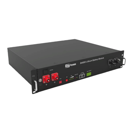
- Page 1 B4850 USER MANUAL Battery Module 48V/50Ah File version-20230724-V2-EN Information might be subject to change without notice during product improving.
-
Page 2: Table Of Contents
Ready for installation ..........................13 Equipment installation ..........................16 4 Use, maintenance and troubleshooting ............... 22 Battery system usage and operation instructions ..............22 Alarm description and processing ....................23 Analysis and treatment of common faults ..................24 ©Dyness reserves the copyright of this document. -
Page 3: Statement Of Law
The storage, use and disposal of the products shall be carried out in accordance with the product manual, relevant contract or relevant laws and regulations. Customer can check the related information on the website of Dyness Digital Energy Technology Co., LTD. when the product or technology is updated. -
Page 4: Safety Precautions
Please charge the battery in 18 hours after it fully discharged or over-discharging protection mode is activated. Formula of theoretical standby time: T=C/I (T is standby time, C is battery capacity, I is total current of all loads). ©Dyness reserves the copyright of this document. -
Page 5: Preface
B4850 ESS Unit User Manual Preface Manual declaration B4850 lithium iron phosphate battery energy storage system can provide energy storage for photovoltaic power generation users through parallel combination. Our product can store extra electricity into battery from photovoltaic power generation system in daytime and supply stable power to user’s equipment as power backup at... -
Page 6: Introduction
B4850 lithium iron phosphate battery system is a standard battery system unit, customers can choose a certain number of B4850 according to their needs, by connecting parallel to form a larger capacity battery pack, to meet the user's long-term power supply needs. - Page 7 This battery product meets European directive requirements. This battery product passed the TUV certification test. Dangerous goods warning label on the top of the battery module © Dyness reserves the copyright of this document.
-
Page 8: Product Specification
Peak Power Charge/Discharge Current (A) 100 (15S) Charge Voltage (Vdc) 53.5 Interface Definition This section elaborates the interface functions of the front interface of the device. 5 6 7 8 Figure 2-1 The sketch of imterface ©Dyness reserves the copyright of this document. - Page 9 When the batteries are connected in parallel, the master communicates with the slaves through the CAN interface. The master summarizes the information of the entire battery system and communicates with the inverter through CAN or 485. © Dyness reserves the copyright of this document.
- Page 10 B4850 ESS Unit User Manual If the master is the latest B4850 battery with DIP switch: 1. The communication cable from the master CAN IN to the inverter comm port should be the correct one. 2. When the battery works with GOODWE, Solis, LUX, Sofar, DEYE(SUNSYNK), VICTRON, IMEON, Sungrow, SMA, RENAC,DELIOS,SAJ(CAN Comm),before starting the battery,you need put the master DIP switch "# 3"...
- Page 11 5. Slave Setting 2 8. If the energy storage system has only one B4850, it is the master itself, and still follow the above steps. Note: For more information of matching inverter brands, please subject to the latest document <The list of compatibility between Dyness ESS and Inverters >.
- Page 12 A special ALM light flashing state:when the communication between batteries is lost or abnormal,all the lights from SOC to RUN of the master battery will flash together. means green light always on means red light always on ● ● Flashing: means green light flashing ©Dyness reserves the copyright of this document.
-
Page 13: Battery Management System(Bms)
When the battery is activated from the shutdown state, if a short circuit occurs, the system starts short-circuit protection for 60 seconds. Self-Shutdown: When device connects no external loads and power supply and no external communication for over 72 hours, device will dormant standby automatically. © Dyness reserves the copyright of this document. - Page 14 B4850 ESS Unit User Manual CAUTION Battery’s maximum discharging current should be more than load’s maximum working current. ©Dyness reserves the copyright of this document.
-
Page 15: Installation And Configuration
There is no flammable explosive materials near to the installation site. The optimal ambient temperature is 15 C~30 Keep away from dust and messy zones Tools and data © Dyness reserves the copyright of this document. - Page 16 Firefighting equipment should be provided near the product, such as portable dry powder fire extinguisher. Automatic fire fighting system shall be provided for the case where necessary. No flammable, explosive and other dangerous product are placed beside the battery. Unpacking inspection ©Dyness reserves the copyright of this document.
- Page 17 /L2050mm dealer to purchase Parallel cable- positive /25mm /L215mm Black Parallel cable- negative /25mm /L215mm Black Communicatio /L250mm/Double n parallel cable RJ45 plug Black Communicatio n cable-to /L2000mm /Double inverter RJ45 plug © Dyness reserves the copyright of this document.
-
Page 18: Equipment Installation
Make sure the power line and ground wire are reasonable. Not easy to short-circuit, water and corrosion. Equipment installation Step1 Installation preparation Confirm that the ON/OFF switch on the front panel of B4850 unit is in the “OFF” state to ensure no live operation. Step 2 Mechanical installation 1. Battery placement position determination 2. - Page 19 7. Turn on the inverter and check the communication between inverter and battery system Installation preparation Prepare equipment and tools for installation. Check the B4850 unit and confirm that the ON/OFF switch is in the "OFF" state to ensure the device is shut off. Mechanical installation Installation method 1: With fixed rack ©...
- Page 20 B4850 ESS Unit User Manual 1. Place the B4850 unit on the cabinet bracket as shown in the figure and push the device into the cabin at the installation position. (The cabinet structure in the figure is for reference only) Figure 3-3 2.
- Page 21 B4850 ESS Unit User Manual 3. Insert the second one B4850 in to the brackets. Figure 3-7 4. Stack the required number of battery and bracket combinations as described above, and fasten the top and bottom buckles. Shown as Figure3-8.
- Page 22 3. The limited continuous current for each pair of power cable is 120A. Please add power cable according to the proportion if the max. working current of the inverter is more than 120A. ©Dyness reserves the copyright of this document.
- Page 23 After the battery system installation is completed and the running is normal, you need to log in to the DYNESS official website to register the product installation and use information to make the product warranty effective. Please follow the instructions on the website to register.
-
Page 24: Use, Maintenance And Troubleshooting
Table 4-1Battery& Inverter power matching table Hybrid Off-grid B4850 Powerbox Inverter Inverter EPS(backup System System Min. port) Output parallel Energy Type Energy AC Output Power number (kWh) (kWh) power ≤1.2kW Powerbox F-2.5 ≤2.4 kW Powerbox F-5.0 ©Dyness reserves the copyright of this document. -
Page 25: Alarm Description And Processing
Alarm description and processing When protection mode is activated or system failure occurred, the alarm signal will be given through the working status indicator on the front panel of the B4850. The network management can query the specific alarm categories. -
Page 26: Analysis And Treatment Of Common Faults
The battery firmware version is not support the inverter If you need any technical help or have any question, please contact the seller in time. ©Dyness reserves the copyright of this document. - Page 27 Address: No. 511 Chenzhuang West Road, Sanshui Street, Jiangyan District, Taizhou City Email: service@dyness-tech.com Tel: +86 400 666 0655 Web: www.dyness.com Official Website Digital version access...
Need help?
Do you have a question about the B4850 and is the answer not in the manual?
Questions and answers