Table of Contents
Advertisement
Quick Links
Advertisement
Table of Contents

Subscribe to Our Youtube Channel
Related Manuals for Dyness POWERBOX Pro


Summary of Contents for Dyness POWERBOX Pro
- Page 1 Powerbox Pro series User Manual POWERBOX Pro User Manual...
- Page 2 Powerbox Pro series User Manual Revision History Revision NO. Revision Date Revision Reason 2022.3.11 1.First Published...
-
Page 3: Table Of Contents
Powerbox Pro series User Manual Content Statement of Law ....................2 Safety Precautions and maintenance instructions ..........3 Preface ........................4 1 Introduction ......................5 1.1 Brief Introduction ....................5 1.2 Product Properties ....................5 1.3 Product identity definition ................... 6 2 Product Specification ..................7 2.1 Size and Weight .................... -
Page 4: Statement Of Law
Powerbox Pro series User Manual Statement of Law Copyright of this document belongs to Daqin New Energy Tech (Taizhou) Co., Ltd. No part of this documentation maybe excerpted, reproduced, translated, annotated or duplicated in any form or by any means without the prior written permission of Daqin New Energy Tech (Taizhou) Co., Ltd. -
Page 5: Safety Precautions And Maintenance Instructions
The surface of the product cabinet is affixed with a torn invalid label. Therefore, before opening the cover to change the DIP switch mode, you need to contact DYNESS and inform the product ID. DYNESS will record this battery ID and authorize the opening operation to be performed. -
Page 6: Preface
Powerbox Pro series User Manual authorized dealer or distributor of DYNESS for a new torn invalid sticker after tearing the original invalid label. When the operation is completed, paste the new one at a different position. Preface Manual declaration Powerbox Pro Lithium Iron Phosphate Battery is external battery module which can store the electricity for home use. -
Page 7: Introduction
1 Introduction 1.1 Brief Introduction Powerbox Pro series is equipped with lithium iron phosphate battery for family use . We base on customer needs and market requirement to develop cutting-edge battery storage technology and offer this high quality product to supply stable electricity for all kind of user’s devices. -
Page 8: Product Identity Definition
Powerbox Pro series User Manual 1.3 Product identity definition FIG1-1 Battery Energy Storage System nameplate Battery voltage is higher than safe voltage, direct contact may cause electric shock hazard. Be careful with your actions and be aware of the dangers. -
Page 9: Product Specification
Powerbox Pro series User Manual 2 Product Specification 2.1 Size and Weight Table 2-1 Powerbox Pro Series Device Model Nominal Dimension Weight Product Series Nominal Voltage IP Level Capacity (mm) (kg) Powerbox Pro 51.2V 200Ah 928×555×210 IP65 2.2 Performance Parameter... -
Page 10: Interface Definition
Powerbox Pro series User Manual 2.3 Interface Definition This section elaborates on interface functions of the front panel of the device. 1 Powerbox Pro the sketch of front interface. Figure2- 1 2 3 4 Table 2-3 Interface Definition Item Name... - Page 11 Item Name Definition When the system is used in parallel: This CAN/RS485 communication socket is connected to the COM IN interface of the next Powerbox Pro through communication cable. (Factory default CAN communication mode) LED1 Module 1 status indicator light...
-
Page 12: Battery Management System(Bms)
Powerbox Pro series User Manual Communication failure between The master LED1 yellow flash batteries 2.4 Battery Management System(BMS) 2.4.1 Voltage Protection Low Voltage Protection in Charging: When any battery cell voltage or total voltage is lower than the rated protection value during discharging, the over-discharging protection is activated, and the battery buzzer makes an alarm sound. -
Page 13: Temperature Protection
Powerbox Pro series User Manual 2.4.3 Temperature Protection Low/Over temperature protection in charging: When battery ’ s temperature is beyond range of 0 ℃ ~+65 ℃ during charging, temperature protection be activated, device stops charging. The protection is released when it back to rated range of working temperature. -
Page 14: Installation And Configuration
Powerbox Pro series User Manual 3 Installation and Configuration 3.1 Preparations for installation Safety Requirement This system can only be installed by personnel who have been trained in the power-supply system and have sufficient knowledge of the power system. The safety regulations and local safety regulations listed below should always be followed during the installation. -
Page 15: Tools And Data
Powerbox Pro series User Manual 3.1.2 Tools and data Tools and meters that may be used are shown in table 3-1. Table 3-1 Tool instrument Screwdriver(Slotted、Phillips) Multimeter Torque wrench Clamp current meter Diagonal pliers Insulation tape Pointed nose pliers Temperature meter... - Page 16 Powerbox Pro series User Manual In the process of unpacking, handle with care and protect the surface coating of the object. Open the package, the professional installation personnel should read the technical documents, verify the list, according to the configuration table and packing list, ensure objects are complete and intact.
-
Page 17: Engineering Coordination
Powerbox Pro series User Manual Power cable ×1 User manual ×1 connect DC breaker with 120ΩCAN resistor ×1 inverter 3.1.5 Engineering coordination Attention should be paid to the following items before construction: Power cable specification. The power cable specification shall meet the requirements of maximum discharge ... -
Page 18: Floor Installation
Powerbox Pro series User Manual Step1 System outage Ensure that the battery is in a shutdown state 1. Hanger mounting Mechanical Step 2 installation 2.Equipment installation 1. Connect the ground cable 2 Electrical installation Electrical Step3 installation 3.Connect inverter 4.Communication interface connection 3.2.1 Floor installation... -
Page 19: Mounted On The Wall
Support bracket and the upper part of the battery box with M6 bolts. 3.2.2 Mounted on the wall The following accessories need to be added when install the powerbox Pro on the wall. Battery bottom bracket ×1 Expansion screw ×4... - Page 20 Powerbox Pro series User Manual Use the positioning cardboard 1. (provided in accessory package) and mark the screw hole positions on the wall, as shown in the four holes on the left. The cardboard must be perpendicular 2. to the ground while drawing the holes.
-
Page 21: Electrical Installation
Powerbox Pro series User Manual 3.2.3 Electrical installation Before connecting the power cables, using multimeter to measure cable continuity, short circuit, confirm positive and negative, and accurately mark the cable labels. Measuring method: Power cable check: select the buzzer mode of multimeter and detect the both ends of the ... - Page 22 Set DIP switch mode of the master module to the correct mode. Before opening the cover to operate, you must contact DYNESS and inform the ID of the product. DYNESS records this battery ID and authorizes the opening operation. Except changing the DIP switch mode, no other operations can be done.
- Page 23 Powerbox Pro series User Manual Connection of Communication interface. Connect the CAN IN port of the battery to the CAN or RS485 communication interface of the inverter using the RJ45 cable. Table 3-3 Pin Definition Foot position Color Definition...
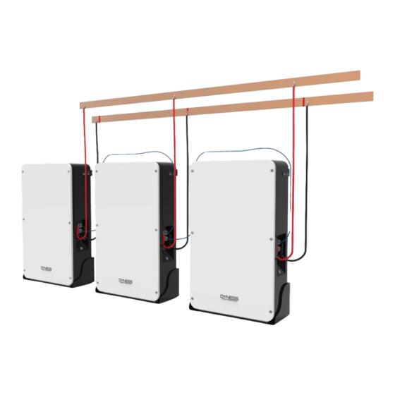
- Page 24 3) When the system used in parallel: When the system is used in parallel, it supports up to 5 Powerbox Pro in parallel. According to the number of parallel system (Take 5 Powerbox Pro in parallel as an example), it needs to use: Power cable ×...
- Page 25 Powerbox Pro series User Manual PINOUT of system parallel communication cable: PINOUT of Battery-Battery communication cable diagram shown as below:...
-
Page 26: Battery Module Dip Switch Definition And Description
Powerbox Pro series User Manual Powerbox Powerbox Powerbox CAN resistor 3.2.4 Battery module DIP switch definition and description Table 3-4 DIP switch Definition DIP switch position (master communication protocol and baud rate selection) Baud rate selection Define different protocols; OFF:CAN: 500K,485: 9600 Distinguish between master and slave ON:CAN: 250K,485: 115200... - Page 27 Powerbox Pro series User Manual DIP switch description: For Powerbox Pro series system, the master module at the bottom of cabinet , the other modules are slaves. Slavemodule SlavePCB Master PCB Front panel Master module When the batteries are connected in parallel, the master communicates with the slaves through the CAN interface.
- Page 28 Powerbox Pro series User Manual Introduction of the initial state of DIP switch of the internal modules of Powerbox Prowith DIP switch. Slave setting 1 ADD:0000 MasterSetting 3 MasterSetting 4 MasterSetting 1 Master Setting 2 ADD:0010 ADD:0100 ADD:0110 ADD:1010 For different inverter model, you need to set different DIP mode: (1) Ensure the communication cable that communicates with the inverter is correct.
- Page 29 Generally factory default DIP switch status of the master module in Powerbox Pro is setting 1. When they are used in parallel, all the slave Powerbox Pro systems need to be opened the cover and change the DIP switch of the master module to Slave Setting 1 (i.e. ADD: 0000),the master powerbox Pro no need change.
- Page 30 If the equation holds after calculation, it means communication between the powerbox Pro is normal. 2. If the Powerbox Pro light board shows three different colors flash alternately, it means the communication between Powerbox Pro is fault. Table 3-5 Battery& Inverter power matching table a) The battery's long-term continuous charging current should be ≤0.5C...
-
Page 31: Battery Parameter Settings On The Inverter
3.2.6 Register on the website after installation After the battery system installation is completed and the running is normal, you need to log in to the DYNESS official website to register the product installation and use information to make the product warranty effective. -
Page 32: Use, Maintenance And Troubleshooting
Powerbox Pro series User Manual 4 Use, maintenance and troubleshooting 4.1 Battery system usage and operation instructions After completing the electrical installation, follow the instruction below to start the battery system. .Check whether the breaker is in OFF state. .Press the battery power button, the power button LED light is on, and 2 LED indicator lights will be on and show the green color after self-check. -
Page 33: Alarm Description And Processing
2 If the battery is over-discharged, please charge the battery within 18h to prevent battery damage; 3 If the battery is damaged, please contact Dyness or professional organization for recycling. 4.2 Alarm description and processing When protection mode is activated or system failure occurred, the LED indicator on the front panel will alarm, through net management can query specific alarm class and take appropriate action. -
Page 34: Alarm And Countermeasure For Non-Affecting System Output
Powerbox Pro series User Manual Buzzer start RED light Stop charging and find out the High temp protection flashing cause of the trouble. Over-current RED light Stop discharge and reduce protection when flashing discharge current below rated discharge Buzzer start value. - Page 35 Powerbox Pro series User Manual The battery cannot be Charging voltage is Adjust charging voltage fully charged too low within 57.1V~57.6V range The power cable sparks Power connection Turn off the battery, check once power on and ALM short-circuit the cause of the short circuit...
- Page 36 Daqin New Energy Tech (Taizhou) Co., Ltd. Address: Building 13, Kunshan Jiangyan Industrial Park, Chenzhuang West Road, Jiangyan District, Taizhou City, Jiangsu Province, China, 225500. Email: Sales@dyness-tech.com Website: www.dyness-tech.com.cn...
Need help?
Do you have a question about the POWERBOX Pro and is the answer not in the manual?
Questions and answers