Table of Contents
Advertisement
Quick Links
Advertisement
Table of Contents

Subscribe to Our Youtube Channel
Related Manuals for Dyness PowerRack HV4


Summary of Contents for Dyness PowerRack HV4
- Page 1 PowerRack HV4 User Manual...
-
Page 2: Table Of Contents
Content Statement of Law ..........................1 Safety Precautions ..........................2 Preface ..............................3 1 Introduction ............................4 1.1 Brief Introduction ........................4 1.2 Product Properties ........................4 1.3 Product identity definition ..................... 4 2 Product Specification ........................6 2.1 System Performance Parameter ..................6 2.2 Battery Module .......................... -
Page 3: Statement Of Law
PowerRack HV4 User Manual Statement of Law Copyright of this document belongs to Daqin New Energy Tech (Taizhou) Co., Ltd. No part of this documentation maybe excerpted, reproduced, translated, annotated or duplicated in any form or by any means without the prior written authorization of Daqin New Energy Tech (Taizhou) Co., Ltd. -
Page 4: Safety Precautions
PowerRack HV4 User Manual Safety Precautions Warning Please do not put the battery into water or fire, in case of explosion or any other situation that might endanger your life. Please connect wires properly while installation, do not reverse connect. -
Page 5: Preface
Preface Manual declaration PowerRack HV4 battery energy storage system can provide energy storage function for photovoltaic power generation users. Our product can store extra electricity into battery from photovoltaic power generation system in daytime and supply stable power to user’s equipment as power backup at nighttime or any time when needed. -
Page 6: Introduction
HV51100 lithium iron phosphate battery system is a high voltage battery system unit, customers can choose a certain number of HV51100 according to their needs, by connecting series to form a PowerRack HV4, to meet the user's long-term power supply needs. The product is especially suitable for application scene of high power, limited installation space, long power backup time and long service life. - Page 7 PowerRack HV4 User Manual Figure1-3 nameplate of HV51100 Battery voltage is higher than safe voltage, direct contact with electric shock hazard. Be careful with your actions and be aware of the dangers. Read the user manual before using. The scrapped battery cannot be put into the...
-
Page 8: Product Specification
PowerRack HV4 User Manual 2 Product Specification 2.1 System Performance Parameter Table 2-1 The parameter of PowerRack HV4 system-1 PowerRack PowerRack PowerRack PowerRack Item HV4 -20 HV4 -25 HV4 -30 HV4 -35 Module Type Nominal Voltage(V) 204.8V 256V 307.2V 358.4V Work Voltage Range(V) 179.2~230.4... -
Page 9: Battery Module
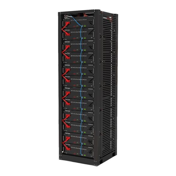
PowerRack HV4 User Manual Figure2-1 PowerRack HV4-56 2.2 Battery Module Table 2-3 Product parameter Module Name HV51100 Cell Technology Li-ion(LFP) Battery Module Capacity (kWh) 5.12 Battery Module Voltage (Vdc) 51.2 Battery Module Capacity (Ah) Battery Module Charge Voltage (Vdc) 57.6... -
Page 10: Interface Definition
PowerRack HV4 User Manual 2.3 Interface Definition This section elaborates the interface functions of the front interface of the device. Figure2-2 The sketch of interface. Table 2-4 Interface Definition Item Name Definition Negative socket Battery output or Serial anode cable... -
Page 11: Communication Port
PowerRack HV4 User Manual Table 2-5 Interface Definition Item Name Definition Positive socket Battery input cable Negative socket Battery input cable The master switch of the battery system ,you must DC Breaker switch on it before switching on power on & power wake switch;... -
Page 12: Battery Management System(Bms)
PowerRack HV4 User Manual Table 2-7 BDU CAN2 & Battery CAN Pin Definition Foot position Color Definition PIN1 Orange/white WAKE PIN2 Orange 24V+ PIN3 Green/white 24V+ PIN4 Blue CANSH PIN5 Blue/white CANSL PIN6 Green 24V- PIN7 Brown/white 24V- PIN8 Brown CANSG 2.4 Battery Management System(BMS) - Page 13 PowerRack HV4 User Manual When battery ' s temperature is beyond range of -20 ℃ ~+55 during discharging, temperature protection is activated, device stops supplying power to the outside. The protection is over when temperature back to rated working range..
-
Page 14: Installation And Configuration
PowerRack HV4 User Manual 3 Installation and Configuration 3.1 Preparation for installation Safety Requirement This system can only be installed by personnel who have been trained in the power supply system and have sufficient knowledge of the power system. The safety regulations and local safety regulations listed below should always be followed during the installation. -
Page 15: Technical Preparation
PowerRack HV4 User Manual Table 3-1 Tool instrument Name Multimeter Screwdriver(Slotted、Phillips) Torque wrench Clamp current meter Diagonal pliers Insulation tape Pointed nose pliers Temperature meter Pliers to hold the wire Anti-static bracelet Stripping pliers Cable tie Electric drill Tape measure 3.1.3 Technical preparation... - Page 16 PowerRack HV4 User Manual Packing list of PowerRack HV4-56 is as follows: Item Specification Quantity Figure Battery- 51V/100Ah HV51100 480×535×133mm BDU100 480×410×155mm Power cable- ² positive /35mm /L3000mm Black Power cable- ² negative /35mm /L3000mm Orange Serial cable ² /35mm...
-
Page 17: Engineering Coordination
PowerRack HV4 User Manual Communication Black Bottom module /L2200mm to BDU CAN2 /Double RJ45 plug Ground wire L3000mm,4mm² PowerRack HV4 User Manual User manual Combination Screw screws M6*14 CAN resistor 120Ω 3.1.5 Engineering coordination Attention should be paid to the following items before construction: Power line specification. -
Page 18: Installation Preparation
PowerRack HV4 User Manual 3.BDU installation 1.Ground cable installation 2.Battery module serial cable installation 3.Connect the module cable-positive from the battery “+” to the BDU “+” 4.Connect the module cable-negative from the battery Electrical “-” to the BDU “-” Step3 installation 5. - Page 19 PowerRack HV4 User Manual 2. Secure the HV51100 unit to the rack with a nut through the mounting holes top on the hanging ears of the HV51100 unit. Figure3-3 3. Insert the second one HV51100 in to the rack. Figure3-4 4.
-
Page 20: Electrical Installation
PowerRack HV4 User Manual 3.2.3 Electrical installation Before connecting the power cables, use multimeter to measure cable continuity, short circuit, confirm positive and negative, and accurately mark the cable labels. Measuring methods: Power cable check: select the buzzer mode of multimeter and detect the both ... -
Page 21: Battery System Self-Test
BDU. Confirm the voltage is within the normal range 3.2.4.4 The output voltage should conform to the voltage range in the table “Table 2-1/2 The parameter of PowerRack HV4 system”. Otherwise, the system will be not working properly. -
Page 22: Connecting Inverter
PowerRack HV4 User Manual 3.2.6 Connecting inverter Caution: A external DC Breaker that operates both positive and negative conductors simultaneously between the BDU and inverter on the power cable is recommended. After waking up the BDU and ensure that the BDU is pre-charged, you can turn on it. -
Page 23: Register On The Website After Installation
After the battery system installation is completed and the running is normal, you need to log in to the DYNESS official website to register the product installation and use information to make the product warranty effective. Please follow the instructions on the website to register. -
Page 24: Maintenance
4.2 Replacement of main component Danger: The PowerRack HV4 battery system is a high voltage DC system, only can be operated by professional and authorized person. 4.2.1 Replacement of Battery Controller (BDU) 4.2.1.1 Turn off the whole battery system. Ensure the Negative terminal and Positive terminal have no power. -
Page 25: Battery Maintenance
PowerRack HV4 User Manual 4.2.1.3 Change a new BDU. Then fix four screws. 4.3 Battery Maintenance Danger: The maintenance of battery only can be operated by professional and authorized person. Danger: you need turn off the battery system firstly when you do some maintenance items. -
Page 26: Shipment
PowerRack HV4 User Manual Caution: The cycle life of the battery will have relative heavily reduction if not follow the above instructions to store the battery for a long term. 6 Shipment Battery module will pre-charged to 50% SOC or according to customer requirement before shipment. - Page 27 Daqin New Energy Tech (Taizhou) Co., Ltd. Address: Building 13, Kunshan Jiangyan Industrial Park, Chenzhuang West Road, Jiangyan District, Taizhou City, Jiangsu Province, China, 225500. Email: Sales@dyness-tech.com Website: www.dyness-tech.com.cn...
Need help?
Do you have a question about the PowerRack HV4 and is the answer not in the manual?
Questions and answers