Dyness B4850 Operation Manual
Ess unit
Hide thumbs
Also See for B4850:
- User manual (22 pages) ,
- User manual (24 pages) ,
- User manual (27 pages)
Table of Contents
Advertisement
Advertisement
Table of Contents

Related Manuals for Dyness B4850


Summary of Contents for Dyness B4850
- Page 1 B4850 ESS Unit Operation Manual TM012 Rev. 003...
-
Page 2: Table Of Contents
Sommario Statement of Law .....................4 Safety .......................6 1.1 Skills of Qualified Personnel ..............6 1.2 Symbols ....................6 1.3 Before Connecting ..................8 1.4 In using ......................9 1.5 Safe handling of lithium batteries guide ............9 1.5.1 Schematic diagram of solution ............9 1.6 Product identity definition ................10 Introduction ....................12 2.1 Brief Introduction ..................12 2.2 Product Properties ..................12 2.3 System parameter ...................13 2.4 Interface Definition ..................14 2.4.1 DIP switch definition and description ...........15 2.5 Battery Management System (BMS) ............18 2.5.1 Voltage Protection ................18... - Page 3 B4850...
-
Page 4: Statement Of Law
STATEMENT OF LAW Copyright of this document belongs to Daqin New Energy Tech (Taizhou) Co., Ltd. No part of this documentation maybe excerpted, reproduced, translated, annotated or duplicated in any form or by any means without the prior written permission of Daqin New Energy Tech (Taizhou) Co., Ltd. All Rights Reserved. This product complies with the design requirements of environmental protection and personal safety. The storage, use and disposal of the products shall be carried out in accordance with the product manual, relevant contract or relevant laws and regulations. Customer can check the related information on the website of Daqin New Energy Tech (Taizhou) Co., Ltd when the product or technology is updated. Web URL: http://www.dyness-tech.com Please note that the product can be modified without prior notice. - Page 5 B4850...
-
Page 6: Safety
1.0 SAFETY B4850 is a high voltage DC system, operated by skilled/qualified personnel only. Read all safety instructions carefully prior to any work and observe them at all times when working on with the system Incorrect operation or work may cause: • injury or death to the operator or a third party; • damage to the system hardware and other properties belonging to the operator or a third party. Skills of Qualified Personnel Qualified personnel must have the following skills: • training in the installation and commissioning of the electrical system, as well as the dealing with hazards; • knowledge of this manual and other related documents; • knowledge of the local regulations and directives. Symbols DANGER Lethal voltage! Battery strings will produce DC power and can cause a lethal voltage and an electric shock. - Page 7 The certificate label for EMC. The certificate label for Safety by TÜV SÜD. The certificate label for Safety by TÜV Rheinland. Danger. Batteries deliver electric power, resulting in burns or a fire hazard when they are short circuited, or wrongly installed. Danger. Lethal voltages are present in the battery terminals and cables. Severe injuries or death may occur if touch the cables and terminals. Warning. Do not open or deform the battery module, otherwise the product will be out of warranty scope. Warning. Whenever working on the battery, wear suitable personal protective equipment (PPE) such as rubber gloves, rubber boots and goggles. Warning. For battery installation, the installer shall refer to NFPA70 or similar local installation standard for operation. Caution. Improper settings or maintenance can permanently damage the battery. Caution. Incorrect inverter parameters will lead to a further faulty/damage to battery. B4850...
-
Page 8: Before Connecting
Caution. It is very important and necessary to read the user manual carefully (in the accessories) before installing or using battery. Failure to do so or to follow any of the instructions or warnings in this document can result in electrical shock, serious injury, or death, or can damage battery, potentially rendering it inoperable. • If the battery is stored for long time, it is required to charge them every six months, and the SOC should be no less than 90%. • Battery needs to be recharged within 12 hours, after fully discharged. • Do not install the product in outdoor environment, or an environment out of the operation temperature or humidity range listed in manual. • Do not expose cable outside. • Do not connect power terminal reversely. • All the battery terminals must be disconnected for maintenance. • Any foreign object is prohibited to insert into any part of battery. • Do not use cleaning solvents to clean battery. • Do not expose battery to flammable or harsh chemicals or vapors. • Do not paint any part of battery, include any internal or external components. • Do not connect battery with PV solar wiring directly. • Please contact the supplier within 24 hours if there is something abnormal. • The warranty claims are excluded for direct or indirect damage due to items above. Before Connecting • After unpacking, please check product and packing list first, if product is damaged or lack of parts, please contact with the local retailer. • Before installation, be sure to cut off the grid power and make sure the battery is in the switched-off mode. -
Page 9: In Using
In using • If the battery system needs to be moved or repaired, the power must be cut off and the battery is completely shut down. • It is prohibited to connect the battery with different type of battery. • It is prohibited to put the batteries working with faulty or incompatible inverter. • It is prohibited to disassemble the battery (QC tab removed or damaged). • In case of fire, only dry powder fire extinguisher can be used, liquid fire extinguishers are prohibited. • Please do not open, repair or disassemble the battery except staffs from Dyness or authorized by Dyness. We do not undertake any consequences or related responsibility which because of violation of safety operation or violating of design, production and equipment safety standards. Safe handling of lithium batteries guide 1.5.1 Schematic diagram of solution B4850... -
Page 10: Product Identity Definition
Product identity definition Fig. 1.1 - Battery Energy Storage System nameplate 10 - Safety... - Page 11 B4850 Safety - 11...
-
Page 12: Introduction
2.0 INTRODUCTION Brief Introduction B4850 lithium iron phosphate battery system is a standard battery system unit, customers can choose a certain number of B4850 according to their needs, by connecting parallel to form a larger capacity battery pack, to meet the user’s long- term power supply needs. The product is especially suitable for energy storage applications with high operating temperatures, limited installation space, long power backup time and long service life. Product Properties B4850 energy storage product’s anode materials are lithium iron phosphate, battery cells are managed effectively by BMS with better performance, the system’s features as below. • Comply with European ROHS, Certified SGS, employ non-toxic, non-pollution environment friendly battery. • Anode materials are lithium iron phosphate (LiFePO4), safer with longer life span. • Carries battery management system with better performance, possesses protection function like over-discharge, over-charge, over-current, abnormal temperature. • Self-management on charging and discharging, Single core balancing function. • Intelligent design configures integrated inspection module. • Flexible configurations allow parallel of multi-battery for longer standby time. • Self-ventilation with lower system noise. • Less battery self-discharge, then recharging period can be up to 10 months during the storage. • No memory effect so that battery can be charged and discharged shallowly. • With wide range of temperature for working environment, -20°C ~ +55°C, circulation span and discharging performance are well under high temperature. •... -
Page 13: System Parameter
System parameter B4850 Charge / discharge current [A] Max charge / discharge current [A] Nominal voltage [V] Nominal capacity [kWh / Ah] 2.4 / 50 Depth of Discharge [%] Module available capacity [kWh / Ah] 2.16 / 45 Charge voltage [V] Disharge voltage [V] Max charge / discharge current [A] Dimension W x H x D [mm] 480 x 90 x 360 Weight [Kg] Comunication RS485, CAN Scalability up to 40 units in parallel Operation Temperature [°C] charge 0 ~ 50 discharge -20 ~ 50 Storage Temperature [°C] -10 ~ 35 Umidity [RH%] 5 ~ 85 Altitude [m] <4000 Protection Class IP20 Operation Life [years] Life cycles >6.000 Cooling system Natural Transfer Certificate TÜV, CE, UN38.3, UL1973, CEI-021... -
Page 14: Interface Definition
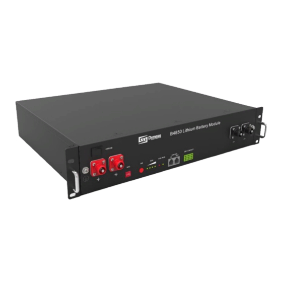
Interface Definition This section elaborates the interface functions of the front interface of the device. Fig. 2.1 - The sketch of interface Pos. NAME DEFINITION Power switch OFF/ON, must be in the “ON” state when in use Ground connection Shell ground connection point Positive socket Battery output positive or parallel positive line Negative socket Battery output negative or parallel negative line SW (battery wake/ When the “OFF/ON” switch button is in the ON state, press sleep switch) and hold this button for 3 seconds to put the battery into the power-on or sleep state. The number of green lights on shows the remaining battery power. See Table 2-3 for details. Red light flashing when an alarm occurs, red light always on during protection status. After the condition of trigger protection is released, it can be automatically closed. Green light flashing during standby and charging mode. Green light always on when discharging. CAN/485 Communication port, support CAN/ RS485 communication (factory default CAN communication) DRY CONTACT DIP switch Tab. 2.2 - Interface Definition 14 - Introduction... -
Page 15: Dip Switch Definition And Description
2.4.1 DIP switch definition and description When the batteries are connected in parallel, the master communicates with the slaves through the CAN interface. The master summarizes the information of the entire battery system and communicates with the inverter through CAN or 485.. Nota: DIP switch from (1) to (3) define different protocols and distinguish between master and slave. DIP switch (4) for Baud rate selection. • DIP switch (4) OFF: set the RS485 baud rate to 9600 and the CAN to 500k • DIP switch (4) ON: set the RS485 baud rate to 115200 and the CAN to 250k The communication cable from the master CAN IN to the inverter comm port should be the correct one. If the master is the latest B4850 battery with DIP switch. SETT. DESCRIPTION Master Set1. When the battery works with GOODWE, Solis, LUX, Sofar, DEYE, VICTRON, IMEON, Sungrow, SMA, RENAC, DELIOS, SAJ(CAN Comm), before starting the battery,you need put the master DIP switch “#3” to the “ON” position (to the top), then turn on the batteries. Master Set2. If the battery communicates with the Axpert-king/VMIII/MAX, Infinisolar, Growatt SPH/SPA(CAN comm), GMDE, turn the master DIP switch “#2” to “ON” position. Master Set3. If the battery communicates with the Growatt SPF HVM-P/ES/WPV by RS485 communication, turn the master DIP switch “#2” and “#3” to “ON”. Master Set4. If the battery communicates with the Schneider Conext Series, turn the master DIP switch “#1” and “#3” to “ON” (MASTER4) Slave Set1. When you setup the master DIP as setting 1~4, all the slaves keep the DIP 0000, no need change. Master Set5. If the battery module is in communication with the ICC by 485 communication, turn the master DIP switch “#1” and “#4” to “ON”. This is only for ICC (a special communication device of some no-communication inverter), it’s a special firmware in BMS, different from general firmware, so if customers want to use that, please contact dyness to confirm. - Page 16 Fig. 2.2 - CAN/485 interface definition: Plug (1), Socket of communication port (2) FOOT POSITION COLOR DEFINITION PIN1 Orange/white 485A PIN2 Orange XGND PIN3 Green/white 485B PIN4 Blue CANH PIN5 Blue/white CANL PIN6 Green Riservato PIN7 Brown/white PIN8 Brown Riservato PIN9 Orange/white Riservato PIN10 Orange XGND PIN11 Green/white Riservato PIN12 Blue CANH PIN13 Blue/white CANL...
- Page 17 STANDBY 5%-25% Flashing 0%-5% Flashing Flashing Flashing 100% Flashing 75%-100% Flashing Flashing Charging 50%-75% Flashing Flashing 25%-50% Flashing Flashing 0%-25% Flashing Flashing 75%-100% 50%-75% 25%-50% Discharging 5%-25% 0%-5% Flashing Flashing Tab. 2.4 - LED status indicators Note: A special ALM light flashing state:when the communication between batteries is lost or abnormal,all the lights from SOC to RUN of the master battery will flash together. = means green light always on = means red light always on Flashing : means green or red light flashing B4850 Introduction - 17...
-
Page 18: Battery Management System (Bms)
Battery Management System (BMS) 2.5.1 Voltage Protection Low Voltage Protection in Discharging: When any battery cell voltage or total voltage is lower than the protection value during discharging, the over-discharging mode is activated, and the battery buzzer makes an alarm sound. Then battery system stops supplying power to the outside. When the voltage of each cell back to rated return range, the protection is over. Over Voltage Protection in Charging: Battery will stops charging when total voltage or any battery cell voltage reaches the rated protection value during charging stage. When total voltage or all cell back to rated range, the protection is over. 2.5.2 Current Protection Over Current Protection in Charging: When the charge current >45A, current limit protection mode is activated, current will be limited to 4A, protection is removed after rated time delaying 10S. Circulate like this until the current is lower than 45A. Over Current Protection in Discharging: When the discharging current is greater than the protection value 55A, the battery buzzer alarms and the system stops discharging. Protection is removed after rated time delaying 1min. -
Page 19: Installation
3.0 INSTALLATION Tools Wire Cutter Crimping Modular Cable Ties Screw Driver Plier Electric Screw Adjustable Wrench Isolating nut drivers Multimeter Driver Tab. 3.1 - Tools needed to install battery pack Danger. Use properly insulated tools to prevent accidental electric shock or short circuits. If insulated tools are not available, cover the entire exposed metal surfaces of the available tools, except their tips, with electrical tape. Safety Gear It is recommended to wear the following safety gear when dealing with the battery pack. Insulating gloves Safety goggles Safety shoes B4850 Installation - 19... -
Page 20: System Working Environments Checking
System Working Environments Checking 3.3.1 Cleaning Warning! The clean condition will cause the isolation characteristic of the system. Before installation and system working, the dust and iron scurf must be clean to ensure the environments cleaning. And the environment must have certain anti-dust ability. The system after long term running must check if the humidity and dust cover or not. If heavy dust cover with high humidity on the system, stop the system running and make clean. 3.3.2 Temperature Caution. B4850: system working temperature range -20° - 55°C; Optimum temperature: 15°C - 30°C. There are no mandatory ventilation requirements for the battery module, but please avoid installation in confined areas. Avoid high salinity, humidity or high temperature conditions. Caution. The installation areas shall avoid of direct sunlight. Out of the working temperature range may cause the battery reduces the cycle of life even trigger the battery system over / low temperature alarm or protection. The room should be equipped with cooling/heating system. If the environment is lower than 0°C, the heating system at first must be turned on. 3.3.3 Fire-extinguisher System Warning. The room must be equipped with fire-extinguisher system for lithium-ion battery. The fire system needs to be regularly checked to be in normal condition. Refer to the using and maintenance requirements of local fire equipment relevant. 3.3.4 Grounding System Warning. Before the battery installation be sure the grounding point of the basement is stable and reliable. If the battery system is installed in an independent equipment cabin (e.g. container), make sure the grounding of the cabin is stable and reliable. The resistance of the grounding system must be ≤100 mΩ. -
Page 21: Handling And Placement
Handling and placement Caution. BESS must be operated by qualified and authorized personnel only. It must be installed in a restricted access area. Warning. Single battery module is 22 kg. If without handling tools must have 2 man to handling with it. • B4850 system must not be immersed in water. Cannot be placed the battery base in rain or other water sources. As a suggestion, the base’s height shall >300mm above the ground. • The base’s weight capacity should support the weight of whole battery system. • B4850 system bust be installed on fixed ground. Fig. 3.1 - Avoid direct sunlight and low-lying place B4850 Installation - 21... -
Page 22: Unpacking Inspection
• Before unpacking, the total number of packages shall be indicated according to the shipping list attached to each package, and the case shall be checked for good condition. • In the process of unpacking, handle with care and protect the surface coating of the object. • Open the package, the installation personnel should read the technical documents, verify the list, according to the configuration table and packing list, ensure objects are complete and intact, if the internal packing is damaged, should be examined and recorded in detail. ITEM Q.TY SPECIFICATION 48V / 50Ah Battery-B4850 480 × 360 × 90 mm Red 25 mm Power cable positive L 2050 mm Black 25 mm Power cable negative L 2050 mm Red 25 mm Parallel cable positive L 215 mm Black 25 mm Parallel cable negative L 215 mm Black L250 mm / Double Communication parallel cable RJ45 plug Communication... -
Page 23: Engineering Coordination
Attention should be paid to the following items before construction: • Power line specification. The power line specification shall meet the requirements of maximum discharge current for each product. • Mounting space and bearing capacity. Make sure that the battery has enough room to install, and that the battery rack and bracket have enough load capacity. • Wiring. Make sure the power line and ground wire are reasonable. Not easy to short-circuit, water and corrosion. Equipment installation 3.7.1 Installation preparation • Prepare equipment and tools for installation • Check the B4850 unit and confirm that the ON/OFF switch is in the “OFF” state to ensure the device is shut off (no live operation). 3.7.2 Cabinet mechanical installation • Battery placement position determination. • Place the B4850 unit on the cabinet bracket as shown in the figure and push the device into the cabin at the installation position. (The cabinet structure in the figure is for reference only). Secure the B4850 unit to the cabinet with a nut through the mounting holes top on the hanging ears of the B4850 unit. B4850 Installation - 23... -
Page 24: Electrical Installation
Fig. 3.2 - Inserimento Fig. 3.3 - Iinstallazione 3.7.3 Electrical installation Before connecting the power cables, use multimeter to measure cable continuity, short circuit, confirm positive and negative, and accurately mark the cable labels. Measuring methods: • Power cable check: select the buzzer mode of multimeter and detect the both ends of the same color cable. If the buzzer calls, it means the cable is in good condition. • Short circuit judgment: choose multimeter resistor file, probe the same end of positive and negative pole, if the resistor shows infinity, means that the cable is available. • After visual testing of power line is connection, the positive and negative poles of the battery shall be connected respectively to the positive and negative poles of the opposite terminal. • It is better to add a circuit breaker between the inverter and the battery system. The selection of the circuit breaker requires: Voltage: U>60V Current: I = Inverter power / 45V Cable connection: 1. Ground cable installation 2. Battery module parallel cable installation 3. Parallel communication cable connection Nota: The BAT-INV comms cable is from inverter comm port to master CAN IN port, BAT-BAT cable is from master CAN OUT to slave1 CAN IN,slave1 CAN OUT to slave2 CAN IN. Battery system self-test 1. Turn the ON/OFF switch to the “ON” state 2. - Page 25 1. C onnect total positive & total negative cable of the battery system to the inverter 2. Battery module total positive cable installation 3. Battery module total negative cable installation 4. C onnect the communication cable from the master CAN IN to the inverter 5. T urn on the Power switch and wake up system by SW button 6. Close the DC breaker between inverter and battery 7. T urn on the inverter and check the communication between inverter and battery system MASTER 1 MASTER 2 MASTER 3 MASTER 4 MASTER 5 SLAVE 1 SLAVE 2 Fig. 3.4 - The circuit breaker (1) is installed between the battery module and the inverter 1) Circuit breaker, 2) Power cable negative, 3) Power cable positive, (4) Parallel cable positive, 5) inverter, 6) Communication cable-to inverter, 7) Parallel cable negative, 8) Communication parallel cable, 9) battery. B4850 Installation - 25...
-
Page 26: Battery Parameter Settings On The Inverter
Note: After the whole system connection,set the master DIP mode according to the inverter model firstly,then start the battery. Note: For more information of matching inverter brands, please subject to the latest document. Each pair of power cable, it’s limited continuous current is 120A, so if the inverter Max.work current more than 120A, please add power cable according to the proportion. 3.7.4 Battery parameter settings on the inverter • Max Charging(Bulk) Voltage: 53.5V • Absorption Voltage: 53V • Float Voltage: 52.5V • Shut Down (cut off) Voltage: 47V • Shut Down (cut off) SOC: 20% • Restart Voltage: 49V • Max Charge Current: 25A * battery QTY • Max Discharge Current: 25A * battery QTY • Capacity: 1*B4850=50Ah 3.7.5 Register on the website after installation After the battery system installation is completed and the running is normal, you need to log in to the DYNESS official website to register the product installation and use information to make the product warranty effective. Please follow the instructions on the website to register. dyness-tech.com -> Service -> Sign. 26 - Installation... -
Page 27: Use, Maintenance And Troubleshooting
4.0 USE, MAINTENANCE AND TROUBLESHOOTING Battery system usage and operation instructions • After completing the electrical installation, follow these steps to start the battery system. • Refer to the description of the DIP switch of 2.3.1 to prepare the battery module before starting up, then press the ON/OFF button to the ON position, next press and hold the SW button for 3 seconds. • After the indicator self-test, the RUN indicator will light and the SOC indicator will be on (100% SOC status in the Figure 4-1). Fig. 4.1 - B4850 Caution: After pressing the power button, if the battery status indicator on the front panel continues to be red, please refer to the “4.2 Alarm description and processing”. If the failure cannot be eliminated, please contact the dealer timely. • Use a voltmeter to measure whether the voltage of the circuit breaker battery access terminal is higher than 42V, and check whether the voltage polarity is consistent with the inverter input polarity. If the circuit breaker battery input terminal has a voltage output and is greater than 42V, then the battery begin to work normally. • After confirming that the battery output voltage and polarity are correct, turn on the inverter, close the circuit breaker. • Check if the indicator of the inverter and battery connection (communication indicator and battery access status indicator) is normal. If it is normal, successfully complete the connection between the battery and the inverter. If the indicator light is abnormal, please refer to the inverter manual for the cause or contact the dealer. - Page 28 HYBRID OFF-GRID B4850 POWERBOX INVERTER INVERTER EPS (backup Min. System System port) parallel Energy Type Energy number (kWh) AC output Power ≤1.2kW F-2.5 ≤2.4 kW F-5.0 ≤3.6 kW F-7.5 ≤4.8 kW F-10.0 ≤6.0 kW 12.0 2* F-7.5 14.4 ≤7.2 kW 14.4 2 * F-7.5 14.4 ≤8.4 kW 16.8 2* F-10.0 19.2 ≤9.6 kW 19.2 2* F-10.0...
-
Page 29: Alarm Description And Processing
Alarm description and processing When protection mode is activated or system failure occurred, the alarm signal will be given through the working status indicator on the front panel of the B4850. The network management can query the specific alarm categories. If the fault such as single cell overvoltage, charging over-current, under-voltage protection, high-temp protection and other abnormalities which affects the output, please deal with it according to Table 4-2. STATUE ALARM CATEGORY ALARM INDICATION PROCESSING Charge Over-current RED, Buzzer start Stop charging and find state out the cause of the trouble High temp Rosso Stop charging Discharge Over-current RED, Buzzer start Stop discharging and state find out the cause of the trouble High temp Rosso Stop discharging and find out the cause of the trouble Total voltage RED, Buzzer start... -
Page 30: Analysis And Treatment Of Common Faults
Analysis and treatment of common faults FAULT PHENOMENON REASON ANALYSIS SOLUTION The indicator does not Total voltage Check the total voltage respond after the power lower than 35V No DC output Battery data status Read the battery information is abnormal. on the monitor Battery gets into over- discharged protection The DC power supply Battery capacity become Storage battery replacement time is too short smaller or add more modules The battery can’t be fully Charging voltage is Adjust charging voltage at charged to 100% too low 53.5V or 54V The power cable sparks Power connection Turn off the battery, check once power on and ALM short-circuit the cause of the short circuit light RED Communication fault... - Page 31 B4850 Use, maintenance and troubleshooting - 31...
- Page 32 Imported by: Energy S.p.A. Piazza Manifattura 1 38068 Rovereto (TN) - Italy Tel: +39 049 2701296 email: service@energysynt.com web: www.energysynt.com DAQIN NEW ENERGY TECH (TAIZHOU) Co.,LTD Address: Building 13, Jiangyan Industrial Park Sanshui Street, Jiangyan District, Taizhou City, Jiangsu Province,225500 Email: sales@dyness-tech.com Website: www.dyness-tech.com...
Need help?
Do you have a question about the B4850 and is the answer not in the manual?
Questions and answers