
Subscribe to Our Youtube Channel
Related Manuals for Dyness RV12100


Summary of Contents for Dyness RV12100
- Page 1 RV12100 Battery Module 12.8V/100Ah RV12100 USER MANUAL USER MANUAL File version-20230607-V1-EN information might be subject to change without notice during product improving.
-
Page 2: Table Of Contents
RV12100 Unit User Manual Contents Statement of Law .........................2 Revision History ............................2 Safety Precautions ........................2 Preface ............................. 3 Manual description ............................ 3 1 Introduction ..........................4 Brief Introduction ............................4 Product Properties ............................. 4 Product identity definition ........................4 Nameplate Label ............................5 2 Product Specification ......................6 Size and Weight ............................ -
Page 3: Statement Of Law
Technology (taizhou) Co., Ltd when the product or technology is updated. Web URL: http://www.dyness-tech.com/ Please note that the product can be modified without prior notice. Revision History Revision NO. Revision Date Revision Reason 2021.12.20 First Published ©Dyness reserves the copyright of this document. -
Page 4: Safety Precautions
Please charge the battery in 18 hours after it discharges fully and starts over-discharging protection. Formula of theoretical standby time: T=C/I (T is standby time, C is battery capacity, I is total current of all loads). ©Dyness reserves the copyright of this document. -
Page 5: Preface
Preface Manual description The RV12100 lithium iron phosphate battery energy storage system can provide energy storage solutions for photovoltaic power generation users through parallel combination. During the day, the excess power of photovoltaic power generation can be stored in the battery. -
Page 6: Introduction
Brief Introduction RV12100 lithium iron phosphate battery system is a standard battery system unit, customers can choose a certain number of RV12100 according to their needs, by connecting parallel to form a larger capacity battery pack, to meet the user's long-term power supply needs.(It is forbidden to use in series) -
Page 7: Nameplate Label
Dangerous goods warning label on the side of the battery module Nameplate Label Figure 1-1 nameplate of RV12100 ©Dyness reserves the copyright of this document. -
Page 8: Product Specification
14kg Performance Parameter Table 2-2 RV12100 performance parameter Nominal Voltage 12.8V Work Voltage Range 11.4~14.4V Nominal Capacity 100Ah Nominal Energy 1.28kWh Nominal Power 0.64KW Max Power 1.28KW Rated Charging Current Rated Discharging Current ©Dyness reserves the copyright of this document. -
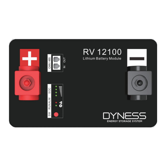
Page 9: Interface Definition
RV12100 Unit User Manual Interface Definition RV12100 product panel interface configuration and function. This section details the interface functions of the front panel of the device. Figure 2-1 RV12100 The sketch of interface Table 2-3 Interface Definition Item Name Definition... - Page 10 Blue/White XGND Green PIN14 XGND PIN15 Brown/White 485B PIN16 Brown 485A Table 2-5 SOC/ALM/RUN Light instructions Battery State LED1 LED2 LED3 LED4 Shut down 75%≤SOC≤100% flash 50%≤SOC<75% flash Standby 25%≤SOC<50% flash 0%<SOC<25% flash ©Dyness reserves the copyright of this document.
-
Page 11: Battery Management System(Bms
The protection is over when it recovers to rated return range. Other Protection Short Circuit Protection: The battery does not allow external short circuit, which will damage the BMS. ©Dyness reserves the copyright of this document. - Page 12 RV12100 User Manual CAUTION Battery's maximum discharging current should be more than load's maximum working current. ©Dyness reserves the copyright of this document.
-
Page 13: Installation And Configuration
And the following conditions are met:Installation location should be away from the sea to avoid brine and high humidity environment;The ground is flat and level;There is no ©Dyness reserves the copyright of this document. - Page 14 No flammable, explosive and other dangerous articles are placed beside the battery.Firefighting equipment should be provided near the equipment, such as portable dry powder fire extinguisher.If necessary, an automatic fire fighting system should be equipped. ©Dyness reserves the copyright of this document.
- Page 15 Bolt cross three combination bolt User Manual User manual Parallel cable- positive /25mm2/L250mm Parallel cable- Black negative /25mm2/L250mm Engineering coordination Attention should be paid to the following items before construction: ©Dyness reserves the copyright of this document.
-
Page 16: Equipment Installation
Equipment installation Table 3-1 Installation steps Step1 Installation preparation 1. Confirm that the light on the front panel of RV12100 unit is off to ensure no live operation Step2 Mechanical installation 1. Battery placement position determination 2. Confirm the direction of battery module installation 3. - Page 17 Positive and negative poles: After the power cable is connected visually, the positive and negative poles of the battery should be connected to the positive and negative poles of the opposite device respectively. Selection requirements for MCB: Voltage:U>24V Current:I = Inverter power/10V ©Dyness reserves the copyright of this document.
- Page 18 3. Remove the nut and washer on the terminal, and connect it with the parallel cable or the total positive and total negative cable, torque 10-12NM. After the cable connection is done, reinstall the plastic protective cover. ©Dyness reserves the copyright of this document.
- Page 19 The battery power cable is connected to the MCB according to the following figure. Wiring diagram for parallel use of modules WARNING The battery can only be used in parallel.Do not use in series.There is a risk of battery damage when used in series. ©Dyness reserves the copyright of this document.
-
Page 20: Use, Maintenance And Troubleshooting
Table 4-1 Battery and inverter power matching table Hybrid inverter Off-grid inverter RV12100 EPS(backup Min.parallel side)ACoutput ACoutput power System energy(kWh) amount power ≤1.2kW ≤2.4 kW ≤3.6 kW ≤4.8 kW ≤6.0 kW 12.0 ©Dyness reserves the copyright of this document. -
Page 21: Alarm Description And Processing
Alarm description and processing When the protection action or fault occurs in the system, the alarm signal will be given through the working status indicator on the front panel of the RV12100. You can query the specific alarm categories through battery monitor. -
Page 22: Analysis And Treatment Of Common Faults
If you have any technical help or question, please contact the seller in time ©Dyness reserves the copyright of this document. - Page 23 Discover Your Nature Official Website Digital version access Address: No. 511 Chenzhuang West Road, Sanshui Street, Jiangyan District, Taizhou City Email: service@dyness-tech.com Tel: +86 400 666 0655 Web: www.dyness-tech.com...
Need help?
Do you have a question about the RV12100 and is the answer not in the manual?
Questions and answers