Table of Contents
Advertisement
Quick Links
Advertisement
Table of Contents

Related Manuals for Deif TRI-2


Summary of Contents for Deif TRI-2
- Page 1 TRI-2 Panorama rudder indicator User's manual...
-
Page 2: Table Of Contents
5.2.1 Setup example ........................................... 5.2.2 Make max. adjustment ......................................... 5.3 Dual CAN setup ............................................5.4 Remote dimmer ............................................5.4.1 TRI-2 and TRI-2 CAN remote dimmer .................................. 6. Technical information 6.1 Specifications ............................................. 6.1.1 TRI-2 and TRI-2 CAN ........................................User's manual 4189350053D EN... -
Page 3: General Information
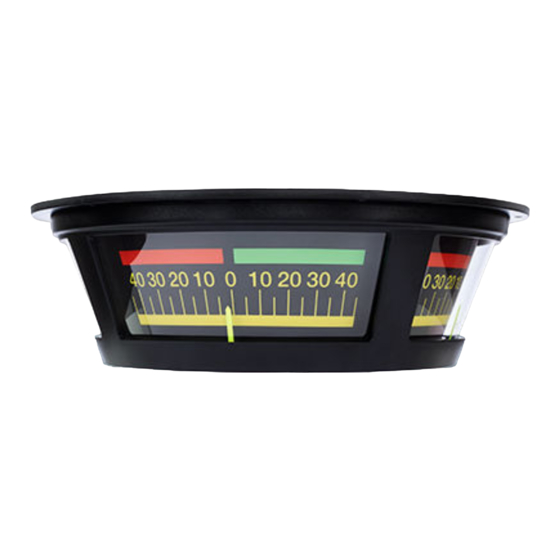
TRI-2 and TRI-2 CAN The rudder angle indicator type TRI-2 and TRI-2 CAN is used for the indication of the rudder position on the bridge. The light intensity can be changed by means of a built-in dimmer accessible on the rear plate of the indicator. Optional remote dimming from a control panel can be used. -
Page 4: Before Using The Product
Please keep the transport lock in case you need to ship the indicator after system test, or in case you need to return the indicator to DEIF for service! Tighten the screws only by hand and with a maximum at 0.5 nM torque to avoid Mounting the rear plate overtighten the screws. -
Page 5: Mounting
2.1.2 Mounting TRI-2 and TRI-2 CAN have been designed for mounting on the ceiling of the bridge. The cables are connected through the rear panel or through the ceiling. Weight: Approx. 1.5 kg. Make sure that the instrument is mounted on an even surface to prevent the instrument housing from deforming. -
Page 6: Setting Up Tri-2
Connection Depending on the ordered version of TRI-2 analogue or CAN version, different connections and settings apply. The analogue versions of the TRI-2 allow only small adjustments whereas it is possible to make more adjustments on the CAN version. Connection of analogue version 3.2.1... -
Page 7: Voltage Input 3-Wire
When the mechanical zero position has been adjusted, it is possible to make adjustments to the maximum position. The rudder must be turned to the maximum position. Adjusting the potentiometer R3 will move the pointer of the TRI-2. When adjusting the 3-wire version, the same procedure is used. But to adjust the maximum, the potentiometer R15 should be used to adjust the maximum deflection. -
Page 8: Setting Up Tri-2 Can
4. Setting up TRI-2 CAN Connection and setup 4.1.1 TRI-2 CAN On the CAN version, the connection terminals are also located under the rear plate on the analogue versions. To make adjustment on sCAN and dual CAN versions, an encoder is used. The encoder (integrated push-button/rotating encoder) is located between the two sets of connectors. -
Page 9: Connections Of Can Version
Single CAN setup The table describes the different settings which can be made for the sCAN version. Depending on the selected operation, it is possible to make changes or see the factory settings of the TRI-2. User's manual 4189350053D EN... -
Page 10: Setup Example
Time-out: if a mode is entered and no changes made, a time-out of 5 minutes will ensure that the TRI-2 will return to normal operation. When a setting has been changed, save command must be used to save the change. This is done by pressing the mode button for more than 5 seconds until the TRI-2 returns back to normal operation. -
Page 11: Make Max. Adjustment
5.2.2 Make max. adjustment Adjustment of the TRI-2 can be set for max. and zero. The TRI-2 will then internally make a linear adjustment from minimum to zero and to maximum. Max. is defined on the left side of the TRI-2, opposite the cable input; see picture below: TRI-2 clockwise rotation When the rotation of the TRI-2 is set to clockwise, the rudder must be positioned at port side when making the max. -
Page 12: Dual Can Setup
Dual CAN setup In normal operation, a double flash on LED 1 and 2 indicates that CAN protocol "Dual CANopen" is in use. If the CAN bus is not detected, wrong writing or wrong protocol may have been ordered. User's manual 4189350053D EN Page 12 of 14... -
Page 13: Remote Dimmer
A plug to seal the hole in the rear plate is included on delivery. The following example is for the TRI-2 with analogue input, but it is similar for the TRI-2 CAN version (however, only 2 wires to the potentiometer is needed). -
Page 14: Technical Information
CAN bus problems can be diagnosed using the colour sequence of the two LEDs behind the Error indications rear plate (see setup tables). TRI-2 CAN NOTE: TRI-2 with analogue input, no special error indications are available User's manual 4189350053D EN Page 14 of 14...
Need help?
Do you have a question about the TRI-2 and is the answer not in the manual?
Questions and answers