Table of Contents
Advertisement
Quick Links
Advertisement
Table of Contents

Related Manuals for TEKTROL Tek-LCD 7802B


Summary of Contents for TEKTROL Tek-LCD 7802B
- Page 2 Disclaimer The information contained in this document is subject to change without notice. Tek- Trol makes no representations or warranties with respect to the contents hereof; and specifically disclaims any implied warranties of merchantability or fitness for a particular purpose. CAUTION: Read complete instructions WARNING: Risk of electric shock or prior to installation and operation of...
-
Page 3: Introduction
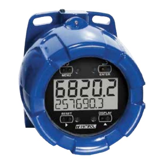
INTRODUCTION The Tek-LCD 7802B is a rugged, explosion-proof loop-powered rate/totalizer fully featured for demanding applications in hazardous areas or in the harshest environmental conditions. The meter derives all of its power from the 4-20 mA loop. It is programmed using the four through-glass buttons, without removing the cover, and can be scaled with or without a calibration signal. -
Page 4: Table Of Contents
Table of Contents INTRODUCTION ---------------------------------------------------------------------- 3 ORDERING INFORMATION ------------------------------------------------------- 3 SPECIFICATIONS -------------------------------------------------------------------- 6 General ------------------------------------------------------------------------------------------- 6 Input ----------------------------------------------------------------------------------------------- 7 Open Collector Output ---------------------------------------------------------------------- 8 Product Ratings and Approvals --------------------------------------------------------- 9 Electromagnetic Compatibility --------------------------------------------------------- 10 SAFETY INFORMATION ---------------------------------------------------------- 10 INSTALLATION ---------------------------------------------------------------------- 11 Unpacking ------------------------------------------------------------------------------------- 11 Pre-Installed Conduit/Stopping Plug ------------------------------------------------- 11 Mounting --------------------------------------------------------------------------------------- 12... - Page 5 Advanced Features Menu & Display Messages ........36 Alarm & Pulse Output (OUTPUT) ..............37 Advanced Function Selection (FUNCTN) ............ 39 Multi-Point Linearization (lnear) ............39 Square Root Linearization (Squar) ............40 Programmable Exponent Linearization (Prog. E ) ........40 Low-Flow Cutoff (CUTOFF) ................
-
Page 6: Specifications
SPECIFICATIONS Except where noted all specifications apply to operation at +25°C. General DISPLAY Five digits 0.70" (17.8 mm) high, 7-segment, (-9999 to 99999) automatic lead zero blanking. Seven characters 0.4" (10.2 mm) high, 14 segment. (Total and/or Tag) 7-digit Totalizer 9,999,999 Symbols High, Low, &... -
Page 7: Input
WEIGHT 5.00 lbs (80 oz, 2.27 kg) WARRANTY 3 years parts and labor Input ACCURACY ±0.03% of calibrated span ±1 count, square root & programmable exponent accuracy range: 10-100% of calibrated span. ADVANCED Linear, square root, or programmable exponent FUNCTION MULTI-POINT 2 to 32 points LINEARIZATION... -
Page 8: Open Collector Output
Open Collector Output Isolated open collector, 30 VDC @ 150 mA max. RATING ALARM OUTPUT Assign to rate for high or low alarm trip point. Assign to total for total alarm trip point. DEADBAND 0-100% FS, user selectable ACKNOWLEDGE Front panel ACK button resets output and screen indication. PULSE OUTPUT K-factor programmable from 0.0001 to 99999. -
Page 9: Product Ratings And Approvals
This information is contained within the serial number with the first four digits representing the year and month in the YYMM format. For European Community: The Tek-LCD 7802B must be installed in accordance with the ATEX directive 94/9/EC, and the product certificate Sira 10ATEX1116X. -
Page 10: Electromagnetic Compatibility
Electromagnetic Compatibility EN 61326:2013 EMISSIONS Safety requirements for measurement, control, and laboratory use Industrial Group 1 Class A ISM emissions requirements Radiated Class A Emissions EN 61326:2013 IMMUNITY Safety requirements for measurement, control, and laboratory use ±4 kV contact, ±8 kV air Amplitude 80-1000 MHz @ 10 V/m, 1.4-2.0 GHz @ 3 V/m,... -
Page 11: Installation
INSTALLATION For Installation in USA: The Tek-LCD 7802B must be installed in accordance with the National Electrical Code (NEC) NFPA 70. For Installation in Canada: The Tek-LCD 7802B must be installed in accordance with the Canadian Electrical Code CSA 22.1. All input circuits must be derived from a CSA approved Class 2 source. -
Page 12: Mounting
Mounting The Tek-LCD 7802B has two slotted mounting flanges that may be used for pipe mounting or wall mounting. Alternatively, the unit may be supported by the conduit using the conduit holes provided. Refer to Mounting Dimensions, page 47 for details. -
Page 13: Table Of Figures Figure 1. Connector Board
Connections (continued) SIGNAL + 4-20 mA signal input positive terminal connection SIGNAL - 4-20 mA signal return/negative terminal connection when not using loop powered backlight. BACKLIGHT + +9-30 VDC when powering backlight from external supply. BACKLIGHT - 4-20 mA signal return/negative terminal when using the installed loop powered backlight or ground/negative when powering backlight from external supply. -
Page 14: Input Signal & Backlight Connections
Input Signal & Backlight Connections Signal and backlight connections are made to a four-terminal connector mounted in the base of the enclosure. For installations without backlight, only the two signal terminals are connected. The 4-20 mA input with no backlight has a maximum voltage drop of 3 V and is wired as shown in Figure 2. -
Page 15: External Reset Connection
+ - + - OUTPUT RESET SAFE-TOUCH BACKLIGHT BUTTONS POWER + - + - UNLOCK LOCK LOOP 9-36 VDC SIGNAL BACKLIGHT 4-20 mA Slide Switch to Transmitter Power 9-36 VDC Supply Power Supply Figure 4. Input Connections with Externally-Powered Backlight It is possible to use the same transmitter (signal loop) power supply for the externally powered backlight. -
Page 16: Open Collector Output Connections
Figure 6, or drive a relay as shown in Figure 7. To avoid damaging the Tek-LCD 7802B care not to wire incorrectly or exceed output ratings. A diode, such as 1N4000 series, will provide protection from relay transients. -
Page 17: Setup And Programming
SETUP AND PROGRAMMING There is no need to recalibrate the meter for milliamps when first received from the factory. The meter is factory calibrated for milliamps prior to shipment. The calibration equipment is traceable to NIST standards. Overview Setup and programming are done through the infrared through-glass buttons, or using the mechanical buttons when uncovered. -
Page 18: Through-Glass Buttons
Through-Glass Buttons The Tek-LCD 7802B is equipped with four sensors that operate as through-glass buttons so that it can be programmed and operated without removing the cover (and exposing the electronics) in a hazardous area. These buttons can be disabled for security by selecting the LOCK setting on the switch located on the connector board in the base of the enclosure. -
Page 19: Buttons And Display
Buttons and Display Button Description Symbol Status Symbol Menu High Alarm Set MENU RESET Right arrow/Reset Low Alarm Set DISPLAY Up arrow/Display Total Alarm Set Enter Password Enabled Enter Press the Menu button to enter or exit the Programming Mode at any time. Press the Right arrow button to move to the next digit or decimal position during programming. -
Page 20: Main Menu Display Functions & Messages
Main Menu Display Functions & Messages The meter displays various functions and messages during setup, programming, and operation. The following table shows the main menu functions and messages in the order they appear in the menu. Display Parameter Action/Setting Enter Setup menu Setup SETUP Enter Decimal Point menu... - Page 21 Display Parameter Action/Setting Disable Manual reset Disable dsabl Enter the Tag/Units Menu Tag/Units Enable Tag/Units Tag On Tag Off Disable Tag/Units Toggle Tag and Total Tag Toggle togle Enter the Password menu Password PASSWRD Program password to lock meter Unlocked UNLOCKD Enter password to unlock meter Locked...
-
Page 22: Main Menu
Main Menu The main menu consists of the most commonly used functions: Setup, Password, and Service. Press MENU button to enter Programming Mode then press the Up Arrow button to scroll through the main menu. Press MENU, at any time, to exit and return to Run Mode. Changes made to settings prior to pressing Enter are not saved. -
Page 23: Setting Numeric Values
Setting Numeric Values The numeric values are set using the Right and Up arrow buttons. Press Right arrow to select next digit and Up arrow to increment digit. The digit being changed blinks. Press the Enter button, at any time, to accept a setting or MENU button to exit without saving changes. -
Page 24: Setting Up The Meter (Setup)
Setting Up the Meter (SETUP) The Setup menu is used to select: Rate and total decimal point position Program menu Rate and total tag display Time base Total conversion factor Manual or automatic total reset function Press the Enter button to access any menu or press Up arrow button to scroll through choices. -
Page 25: Setting The Decimal Point (Dec. P T)
Setting the Decimal Point (dec. P T) Rate decimal point may be set with up to four decimal places or with no decimal point at all. Total decimal point may be set with up to six decimal places or with no decimal point at all. -
Page 26: Programming The Meter (Prog)
Programming the Meter (PRoG) It is very important to read the following information, before proceeding to program the meter: There is no need to recalibrate the meter for milliamps when first received from the factory. The meter is factory calibrated for milliamps prior to shipment. The calibration equipment is traceable to NIST standards. -
Page 27: Scaling The Meter (Scale)
Scaling the Meter (SCale) The 4-20 mA input can be scaled to display the process in engineering units. A signal source is not needed to scale the meter; simply program the inputs and corresponding display values. Figure 8. Scale Menu For instructions on how to program numeric values see Setting Numeric Values, page 23. -
Page 28: Calibrating The Meter (Cal)
Calibrating the Meter (Cal) To scale the meter without a signal source, refer to Scaling the Meter (SCale), page 27. The meter can be calibrated to display the process in engineering units by applying the appropriate input signal and following the calibration procedure. The use of a calibrated signal source is strongly recommended. -
Page 29: Re-Calibrating The Internal Calibration Reference (Ical)
Minimum Input Span The minimum input span is the minimum difference between input 1 and input 2 signals required to complete the calibration or scaling of the meter. The minimum span is 0.10 mA. If the minimum span is not maintained, the meter reverts to input 2, allowing the appropriate input signals to be applied. -
Page 30: Setting The Total Conversion Factor (Totcf)
Setting the Total Conversion Factor (totCF) Total Conversion Factor is used to convert to a different unit of total display. For example, to display rate in gallons and total in liters, enter a conversion factor of 3. 7 854. When rate and total units are the same, the Conversion Factor should be 1. -
Page 31: Manual Or Automatic Total Reset Function (T Rst)
Manual or Automatic Total Reset Function (t rST) The meter may be programmed to reset the total either manually using the Reset button or automatically. Manual reset button may be disabled to avoid inadvertent total reset. The automatic reset is based on the set point programmed in the Advanced menu: total. -
Page 32: Setting The Tag Display (Tag)
Setting the Tag Display (tag) The meter can be set to display a combination of seven alphanumeric characters for engineering units (e.g. GALLONS) or for identification (e.g. TANK 3). Press Right arrow to select next unit and Up arrow to increment unit. To automatically cycle the lower display between total reading for ten seconds and tag for two seconds, choose tOgle. -
Page 33: Setting Up The Password (Passwrd)
Setting Up the Password (PASSWRD) The Password menu is used to program a five-digit password to prevent unauthorized changes to the programmed parameter settings. The lock symbol is displayed to indicate that settings are protected. Locking the Meter Enter the Password menu and program a five-digit password. For instructions on how to program numeric values see Setting Numeric Values, page 23. -
Page 34: Disabling Password Protection
Disabling Password Protection To disable the password protection, access the Password menu and enter the correct password twice, as shown below. The meter is now unprotected until a new password is entered. Enter Password Run Mode 3024. 7 00000 LOCKED GALLONS LOCKED UNLOCKD... -
Page 35: Advanced Features Menu
Advanced Features Menu To simplify the setup process, functions not needed for most applications are located in the Advanced features menu. Press and hold the MENU button for five seconds to access the Advanced features menu. Press the Enter button to access any menu or press Up arrow button to scroll through choices. -
Page 36: Advanced Features Menu & Display Messages
Advanced Features Menu & Display Messages The following table shows the Advanced features menu functions and messages in the order they appear in the menu. Display Parameter Action/Setting Enter output menu Output OUTPUT Disable output Enter alarm output menu Alarm Output Alrm Assign alarm output to rate Rate Alarm... -
Page 37: Alarm & Pulse Output (Output)
Setting Numeric Values, page 23. Alarm & Pulse Output (OUTPUT) The Tek-LCD 7802B is equipped with an NPN open collector output that may be set up for high or low rate alarm trip point, total alarm trip point, or pulse output based on K-factor. - Page 38 Alarm Output (alrnm) Rate high alarm trip point: program set point above reset point. Rate low alarm trip point: program set point below reset point. Rate alarm deadband is determined by the difference between set and reset points. Minimum deadband is one display count. If set and reset points are pro- grammed the same, output will reset one count below set point.
-
Page 39: Advanced Function Selection (Functn)
Advanced Function Selection (FUNCTN) The Advanced Function menu is used to select the advanced function to be applied to the input: linear, square root, programmable exponent, or round horizontal tank volume calculation. The multi-point linearization is part of the linear function selection. Meters are set up at the factory for linear function with 2-point linearization. -
Page 40: Square Root Linearization (Squar)
LnEAR FUNCTN PROGRAM PROGRAM inP 1 dsp 1 0000. 0 DSPLY 1 INP 2 Figure 9. Multi-Point Linearization Menu Square Root Linearization (Squar) The square root function can be used to linearize the signal from a differential pressure transmitter and display flow rate in engineering units. Programmable Exponent Linearization (Prog. -
Page 41: Low-Flow Cutoff (Cutoff)
Low-Flow Cutoff (CUTOFF) The low-flow cutoff feature allows the meter to be programmed so that the often- unsteady output from a differential pressure transmitter, at low flow rates, always displays zero on the meter. The default cutoff is zero to prevent negative readings, but this may be overridden to allow them. -
Page 42: Internal Calibration (Ical)
Internal Calibration (ICAL) There is no need to recalibrate the meter for milliamps when first received from the factory. The meter is factory calibrated for milliamps prior to shipment. The calibration equipment is traceable to NIST standards. The internal calibration allows the user to scale the meter without applying a signal. The use of a calibrated signal source is necessary to perform the internal calibration of the meter. -
Page 43: Operation
OPERATION Front Panel Buttons Operation Button Description Symbol Press to enter or exit Programming Mode or exit Max/Min readings MENU RESET Press to reset total (if enabled) Press to reset Max/Min readings DISPLAY Press to display Max/Min readings alternately Press to acknowledge alarm (if enabled) Press to display Max or Min reading indefinitely while displaying Max or Min Enter... -
Page 44: Maximum & Minimum Readings (Maximum & Minimum)
Maximum & Minimum Readings (MAXIMUM & MINIMUM) The maximum and minimum (peak & valley) readings reached by the rate are stored in the meter since the last reset or power-up. The meter shows MAXIMUM or MINIMUM to differentiate between run mode and max/min display. Press Enter to remain in Max/Min display mode. -
Page 45: Factory Defaults & User Settings
Factory Defaults & User Settings The following table shows the factory setting for most of the programmable parameters on the meter. Next to the factory setting, the user may record the new setting for the particular application. Model: ______________ S/N: _______________ Date: _________ Parameter Display Default Setting... -
Page 46: Troubleshooting
TROUBLESHOOTING The rugged design and the user-friendly interface of the meter should make it unusual for the installer or operator to refer to this section of the manual. If the meter is not working as expected, refer to the recommendations below. Troubleshooting Tips Symptom Check/Action... -
Page 47: Mounting Dimensions
MOUNTING DIMENSIONS All units: inches [mm] 3.35 [85.1] 2.25 [57.1] 0.32 [8.2] 5.65 [143.5] 5.25 [133.4] Figure 10. Enclosure Dimensions Front View... -
Page 48: Figure 11. Enclosure Dimensions Side Cross Section View
3.35 [85.0] 4.15 [105.5] 4.86 [123.5] 3.22 [81.9] Figure 11. Enclosure Dimensions Side Cross Section View... -
Page 49: Quick User Interface Reference
QUICK USER INTERFACE REFERENCE Pushbutton Function Menu Go to Programming Mode or leave Programming, Advanced Features, and Max/Min Modes. Right Arrow Move to next digit or decimal point position. Reset Total. Up Arrow Move to next selection or increment digit. Go to Max/Min Mode. Enter/Ack Accept selection/value and move to next selection. -
Page 51: Eu Declaration Of Conformity
EU DECLARATION OF CONFORMITY Issued in accordance with ISO/IEC 17050-1:2004 and ATEX Directive 2014/34/EU. Precision Digital Corporation 233 South Street Hopkinton, MA 01748 USA as the manufacturer, declare under our sole responsibility that the product(s), Model PD6820 Loop Powered Rate/Totalizer to which this declaration relates, is in conformity with the European Union Directives shown below: 2014/35/EU... - Page 52 Tek-Trol LLC 796 Tek Drive Crystal Lake, IL 60014 USA Tel.: +1 847 857 6076 Fax: +1 847 655 6147 Email: tektrol@tek-trol.com www.tek-trol.com Flow | Level | Temperature | Pressure | Valves | Analyzers | Accessories | TekValSys...
Need help?
Do you have a question about the Tek-LCD 7802B and is the answer not in the manual?
Questions and answers