
Related Manuals for TEKTROL TEK-VOR 1300C


Summary of Contents for TEKTROL TEK-VOR 1300C
- Page 1 Technology Solutions OR 1300C Vortex Mass Flowmeter Instruction Manual Document Number: IM-1300C 1.800.561.8187 information@itm.com www. .com...
- Page 2 NOTICE Read this manual before working with the product. For personal and system safety, and for optimum product performance, make sure you thoroughly understand the contents before installing, using, or maintaining this product. © COPYRIGHT Tek-Trol LLC 2021 No part of this publication may be copied or distributed, transmitted, transcribed, stored in a retrieval system, or translated into any human or computer language, in any form or by any means, electronic, mechanical, manual, or otherwise, or disclosed to third parties without the express written permission.
-
Page 3: Table Of Contents
Table of Contents Safety Instructions ....................3 Intended Use ....................... 3 Certification ......................... 3 Safety Instructions from the Manufacturer ..............3 1.3.1 Disclaimer .......................... 3 1.3.2 Product Liability and Warranty ..................3 1.3.3 Information Concerning the Documentation ..............3 Safety Precautions ....................... 3 Packaging, Transportation and Storage ................. - Page 4 5.4.1 How to download the application ................... 39 5.4.2 Access the application ..................... 39 5.4.3 Utilize the application ..................... 39 Maintenance ......................40 How to Rotate Transmitter Head ................40 Replace a Transmitter Circuit Board ................40 Replace the Pressure Sensor ..................41 Troubleshooting ......................
-
Page 5: Safety Instructions
1 Safety Instructions 1.1 Intended Use Tek-Vor 1300C is primarily used to measure volumetric flow rate of gas, steam, and liquids. It is suitable for SIP and CIP process in food, beverage, and pharmaceutical industries. It is also used in water and wastewater industry. -
Page 6: Packaging, Transportation And Storage
1.5 Packaging, Transportation and Storage 1.5.1 Packaging The original package consists of 1. Tek-Vor 1300C Vortex Flowmeter 2. Documentation NOTE Unpack and check the contents for damages or signs of rough handling. Report damage to the manufacturer immediately. Check the contents against the packing list provided. -
Page 7: Storage
• Verify local safety regulations, directives, and company procedures with respect to hoisting, rigging, and transportation of heavy equipment. • Transport the product to the installation site using the original manufacturer’s packing whenever possible. 1.5.3 Storage If this product is to be stored for a long period of time before installation, take the following precautions: •... -
Page 8: Product Description
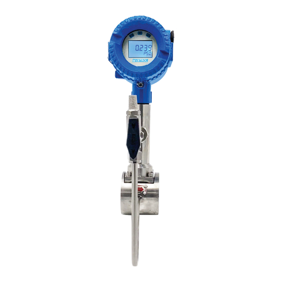
This section covers the reference and specification data, as well as ordering information. 2.1 Introduction Tek-Vor 1300C Vortex Flowmeter (also called a Vortex Shedding Flowmeter) is a versatile instrument that calculates the mass flow, volumetric flow rate, temperature, and pressure and density of any liquid, gas, or steam through a pipeline. - Page 9 = Strouhal Number V = Flow Velocity d = Width of the Bluff Body The Vortex Shedding frequency is directly proportional to the velocity of any given bluff body diameter. �� = �� × �� Where, k = A constant for all fluids on the given design of flowmeter Hence, ��...
-
Page 10: Specifications
2.3 Specifications 2.4 Dimensional Drawings • Size and Dimension for Wafer Type 1.800.561.8187 information@itm.com www. .com... - Page 11 L (Pipe C (Flange M (Screw Meter Flange (Size) (Pipe length) (Flange thickness) hole (Screw height screw diameter) qty.) (mm) (mm) hole (mm) (mm) (mm) distance) (mm) (mm) 1" 3.58" 2.55" 3.93" 0.70" (18) 0.51" (13) 11.35" 5.11" (25) (91) (65) (100) (288.5)
- Page 12 K (pipe L (Pipe C (Flange M (Screw Meter (Size) length) (Flange thickness) hole (Screw height in. (mm) screw diameter) qty.) (mm) (mm) hole (mm) (mm) distance) (mm) (mm) 1" 4.33" 7.08" 3.12" 0.57" 0.62" 11.63" (25) (110) (180) (79.4) (14.7) (16) (295.5)
- Page 13 Size K (pipe L (Pipe Meter Flange length (Flang (Flang (Screw (Screw height conde conde (mm) ) In. hole qty.) nsatio nsatio (mm) (mm) screw thickn dia- (mm) (mm) n pipe n pipe hole ess) In. meter) height length distan (mm) ce) In.
- Page 14 M (Screw Meter Flange (Size) (Pipe (Pipe (Flange (Flange hole (Screw height condensa length) screw thickness) diameter) qty.) tion pipe (mm) hole (mm) (mm) height (mm) (mm) distance) (mm) (mm) (mm) (mm) 1" 4.33" 7.08" 3.12" 0.57" 0.62" 11.63" 6.71" 5.35"...
-
Page 15: Model Chart
2.5 Model Chart Tek-Vor Example 050S Tek-Vor 1300C-050S-W-R-M-1-B 1300C Tek-Vor Series Vortex Mass Flowmeter 1300C 015S 1/2", +/- 1.0% Accuracy, Standard Vortex Meter 025S 1", +/- 1.0% Accuracy, Standard Vortex Meter 040S 1-1/2", +/- 1.0% Accuracy, Standard Vortex Meter 050S 2", +/- 1.0% Accuracy, Standard Vortex Meter... -
Page 16: Installation
3 Installation This section covers instructions on installation and commissioning. Installation of the device must be carried out by trained; qualified specialists authorized to perform such works. CAUTION • When removing the instrument from hazardous processes, avoid direct contact with the fluid and the meter •... -
Page 17: Installation Condition
• Install and maintain flowmeter by person who has the knowledge of flowmeter. • Install flowmeter sensor and its pipe correctly, make sure the seal and safety, liquid pressure shall be no more than the maximum working pressure on nameplate. •... - Page 18 • Installation for Single Bend Pipeline • Installation for Double Bend Pipeline • Installation when Valve is at Downstream • Installation when Valve is at Upstream • Installation when Temperature and Pressure Sensors are at Downstream 1.800.561.8187 information@itm.com www. .com...
- Page 19 • Installation when Roots Blower, Piston Blower, or Compressor are at Upstream • Installation of a Flowmeter after a Piston Pump • Installation when T-type Pipeline is at Upstream 1.800.561.8187 information@itm.com www. .com...
-
Page 20: Electrical Installation
Safety Instructions or Installation or Control Drawings. 4.1 Terminal Board The Tek-Vor 1300C has two different terminal boards; a 5-terminal board for standard models and a 12-terminal board for multi-variable models. 1.800.561.8187 information@itm.com... -
Page 21: Wiring For A 5-Terminal Board
Power supply Pulse output RS485 communication Current Temperature sensor RTD1, RTD2, RTD3 Pressure Sensor On the above boards, V+ and V- are for power. is the pulse output terminal. A, B are “+” and “-” terminals for RS485 Modbus communication. I+ and I- are “+” and “–“ for 3-wire or 4-wire 4 to 20 mA. -
Page 22: Wiring For A 2-Wire Hart With 4 To 20Ma
4.2.2 Wiring for a 2-Wire HART with 4 to 20mA When there is no temperature and pressure compensation and the power source is 24VDC, the maximum load for 4 to 20mA analog is 500 ohms. When there is temperature and pressure compensation and the power source is 24VDC, the maximum load for 4 to 20mA analog is 400 ohms. -
Page 23: Wiring For A 3-Wire Hart With 4 To 20Ma
resistor between “ “ and “V-”; the resistance should be within 500Ω to 1000Ω, and the power consumption should be no less than 0.5W. 4.3.2 Wiring for a 3-Wire HART with 4 to 20mA When the power source is 24VDC, the maximum load for 4 to 20mA analogue is 500 ohms. 1.800.561.8187 information@itm.com www. -
Page 24: Wiring For A 4-Wire Hart With 4 To 20Ma
4.3.3 Wiring for a 4-Wire HART with 4 to 20mA When the power source is 24VDC, the maximum load for 4 to 20mA analogue is 500 ohms. 4.3.4 Wiring for RS485 1.800.561.8187 information@itm.com www. .com... -
Page 25: Operation
This section covers operation techniques and guidelines. 5.1 Display The Tek-Vor 1300C Vortex Flowmeter provides local settings and a display panel. It can display several variables on this multifunctional LCD display. It has 3 buttons. 5.1.1 Introduction to the Multi-Functional LCD Display The Tek-Vor 1300C Vortex Flowmeter has a display to indicate “Frequency”, “Flow Rate”, and... -
Page 26: Units Of The Variable Displayed
MPa or kPa FREQ Frequency DENS Density kg/m 5.1.3 Three Button Setting Tek-Vor 1300C vortex flowmeter has three buttons on the top of the display, which are used as L-R button, used as U-D button, used as Enter button. 1.800.561.8187 information@itm.com www. -
Page 27: Total Flow Display
5.1.4 Total Flow Display The Tek-Vor 1300C can display 9 digits to the left of decimal point and 3 digits to the right of it. When there is more than 6 digits, the total flow reading will be displayed twice; first it will display digits on right, and then second the digits on left. -
Page 28: Parameter Setting
5.2 Parameter Setting The Tek-Vor 1300C Vortex Flowmeter has Digit and Code Setting functions. Use the Code Setting function to set parameters such as fluid type, compensation type, and output signal. Use the Digit Setting function to set parameters related to a number such as pipe size, flow range factor. -
Page 29: Digit Setting
setting is available, the setting made will be cancelled and the display will not flash. If this happens, press “L-R” or “U-D” to set it again. When the display is not flashing, press “Enter” to save and go to the next setting. If the user wants to quit the code setting function, hold down “Enter”... -
Page 30: Setting Address
5.2.3 Setting Address • Code Setting Address NOTE If the unit of flow rate is changed or the measurement is changed from the flow rate to mass flow, users can reset the total flow to 0 or record the current total flow: Total flow= (number of times over total flow) * (maximum display of total flow) + (Current total flow reading) - Page 31 Frequency Output for Total Flow, Set Factor in D013 200-1000Hz Output Flow Rate Parameter Temperature Pressure Damping 01 to 1 to 99 Seconds Instrument Number 00 to For Modbus 00 to For HART Communication Baud Rate 1200 No Parity 1 Stop Bit 1200 Even Parity 1 Stop Bit 2400 No Parity 1 Stop Bit 2400 Even Parity 1 Stop Bit...
- Page 32 Temperature Unit Right Digits Number 00 to 00:No Right Digits for Total for Total Flow Flow 01 to 05:1 to 5 Right Digits for Total Flow 1st Row Display Flow Rate Parameter Percentage of Flow Rate to Flow Range Lower Row Display No Display Parameter Total Flow...
- Page 33 • Digit Setting Address Digit Setting Item Code Description of Code Address Max Pressure [-99999, 999999] Max Input/Output Pressure Min Pressure [-99999, 999999] Min Input/Output Pressure [-99999, 999999] Max Input/Output Temperature Temperature [-99999, 999999] Min Input/Output Temperature Temperature Pre-set Density When C02=01, the [0,999999] Flowmeter will use this...
-
Page 34: Example Of Setting
5.2.4 Example of Setting For Tek-Vor 1300C Vortex Flowmeter, measure gas in a 2” (DN50) pipe; K factor= 7.802P/L, density pre-set, mass flow display unit is kg/h. 4 to 20mA output with a flow range of 0 to 4000kg/hr. -
Page 35: Communication Using Rs485 Modbus
5.3 Communication using RS485 MODBUS • Interface Regulation 1. The communication interface should be RS485, the range of Baud rate should be 1200 to 115200 2. The wiring terminal for communication is “A” and “B”. Refer to the Electrical Installation Section for Wiring Terminal information 3. - Page 36 b. Addresses of Code Setting Resister Usage Range Nature Date Type 1000 Fluid Type C01 Read Only Short 1001 Density Read/Write Short Compensation 1004 Output C05 Read/Write Short 1005 200-1000Hz Read/Write Short Output Parameter C06 1006 Damping C07 1-99 Read/Write Short 1007 Instrument...
- Page 37 1032 Third Read/Write Short Parameter Displayed in Circle Display 1033 Fourth Read/Write Short Parameter Displayed in Circle Display 1034 Fifth Parameter Read/Write Short Displayed in Circle Display 1035 Read/Write Short 1036 0-10 Read/Write Short 1037 Sequence of Read/Write Short Float C38 1046 Password Read...
- Page 38 c. Addresses of Digit Setting Resister Usage Restriction of Nature Date type modification 2000 to D001 Max -1e5 to 1e6 Read/Write Float 2001 Pressure 2002 to D002 Min -1e5 to 1e6 Read/Write Float 2003 Pressure 2004 to D003 Max -1e5 to 1e6 Read/Write Float 2005...
- Page 39 • Command Function codes 03 and 04 are the codes supported for reading the registers. Function code 06 is for writing one register. Function code 16 is for writing multiple registers. Function code 06 is only supported for writing a short date. Function code 16 is supported for writing both a short date and a float date.
- Page 40 c. Function Code 16 – Write Multiple Registers Request Response 01: Address 01: Address 10H: Function code 10H: Function code 00: Register address higher 00: Register address higher 01: Register address lower (digital 01: Register address lower setting address) 00: Quantity of register higher 00: Quantity of register higher 02: Quantity of register lower 02: Quantity of register lower...
-
Page 41: Bluetooth Access
5.4 Bluetooth Access 5.4.1 How to download the application • Visit Apple’s application store • Search “Tek-trol Bluetooth” or “Tek-Bluetooth” to find our app profile • Download the application 5.4.2 Access the application • Open application • Enter login information (ID: 20000000007, Verify code:341234) •... -
Page 42: Maintenance
6 Maintenance This section covers maintenance techniques and guidelines. 6.1 How to Rotate Transmitter Head • Before rotating the transmitter, please take out the tightening screw under the transmitter • Rotate transmitter head up to 180 and tighten the screw 6.2 Replace a Transmitter Circuit Board •... -
Page 43: Replace The Pressure Sensor
6.3 Replace the Pressure Sensor • Make sure the pressure valve on the meter is off before replacing the pressure transmitter • Loosen the nut that is holding the pressure sensor • Remove the front cover, loosen the circuit board and remove the wiring of the pressure sensor •... - Page 44 Energy Threshold Value is Check if the Energy Set the Energy too High threshold value is too threshold value to a high in spectrum proper value analyzing checking mode Transmitter Function Replace the transmitter Replace the Failure with another transmitter transmitter of same type to check Sensor is Damaged...
-
Page 45: Self-Diagnostic Messages
the pressure and need to install a filter temperature of the at upstream of the fluid. flowmeter. If the fluid is liquid-gas two phase flow, need to install a getter at upstream of the flowmeter. Transmitter Failure Replace the transmitter Replace the with another transmitter... - Page 46 Err-011 Superheated Steam Reduce the Steam Temperature is Over Limited Temperature Err-012 Superheated Steam Pressure Reduce the Steam Pressure is Over Limited Err-013 Button is Pressed and Hold Check the Button Circuit for too Long Time Err-014 Reset Code Setting Failed Check EEPROM Err-015 Reset Digit Setting Failed...
- Page 47 Tek-Trol is a fully owned subsidiary of TEKMATION LLC. We o er our customers a comprehensive range of products and solutions for process, power and oil & gas industries. Tek-Trol provides process measurement and control products for Flow, Level, Temperature & Pressure Measurement, Control Valves & Analyzer systems.
Need help?
Do you have a question about the TEK-VOR 1300C and is the answer not in the manual?
Questions and answers