
Related Manuals for TEKTROL TEK-C LAMP 1200A-100H


Summary of Contents for TEKTROL TEK-C LAMP 1200A-100H
- Page 1 Technology Solutions LAMP 1200A-100H Handheld Ultrasonic Flow Meter Instruction Manual Document Number: IM-1200A-100H www.tek-trol.com...
- Page 2 www.tek-trol.com NOTICE Read this manual before working with the product. For personal and system safety, and for optimum product performance, make sure you thoroughly understand the contents before installing, using, or maintaining this product. For technical assistance, contact Customer Support 796 Tek-Drive Crystal Lake, IL 60014 Tel: +1 847 857 6076...
-
Page 3: Table Of Contents
Table of Contents Safety Instructions ......................3 Intended Use ........................3 Safety Instructions from the Manufacturer .................3 1.2.1 Disclaimer ..........................4 1.2.2 Product Liability and Warranty ....................4 1.2.3 Information Concerning the Documentation ................4 1.2.4 Safety Precautions ........................4 1.2.5 Packaging, Transportation and Storage .................. - Page 4 4.3.4 Keypad ........................... 23 4.3.5 Menu Windows ........................24 4.3.6 Menu Window List ........................ 25 4.3.7 Steps to Configure the Parameters ..................26 Menu Window Details....................27 Troubleshooting ......................31 No Display ........................31 Exciting Alarm ........................31 Empty Pipe Alarm ......................31 Measure Flow Disallow ....................
-
Page 5: Safety Instructions
1 Safety Instructions Please read this manual carefully and completely before you use the device for the first time. The device may only be used by qualified personnel and repaired by Tek-Trol LLC personnel. Damage or injuries caused by non-observance of the manual are excluded from our liability and not covered by our warranty. -
Page 6: Disclaimer
1.2.1 Disclaimer The manufacturer will not be held accountable for any damage that happens by using its product, including, but not limited to direct, indirect, or incidental and consequential damages. Any product purchased from the manufacturer is warranted in accordance with the relevant product documentation and our Terms and Conditions of Sale. -
Page 7: Packaging, Transportation And Storage
NOTE Indicates that operating the hardware or software in this manner may damage it or lead to system failure. 1.2.5 Packaging, Transportation and Storage 1.2.5.1 Packaging The original package consists of 1. Tek-Clamp 1200A-100H Handheld Ultrasonic Flow Meter 2. Documentation 1.2.5.2 Delivery Contents •... -
Page 8: Transportation
1.2.6 Transportation • Avoid impact shocks to the device and prevent it from getting wet during transportation. • Verify local safety regulations, directives, and company procedures with respect to hoisting, rigging, and transportation of heavy equipment. • Transport the product to the installation site using the original manufacturer’s packing whenever possible. -
Page 9: Product Description
2 Product Description This section covers the reference and specification data, as well as ordering information. 2.1 Introduction Tek-Clamp 1200A-100H Handheld Ultrasonic Flow Meter is a completely non-invasive Ultrasonic Flow Meter. The flow meter uses the ultrasonic signal to measure the flow rates with the transit time method. -
Page 10: Specifications
The sound passes through the pipe or liquid diagonally. The selection of the right method depends on the characteristics of the liquid. 2.3 Specifications 2.3.1 Technical Specifications for Hand-Held Device ±1% of reading at rates >0.2 mps Accuracy 0.03 to 100ft/sec Velocity Range 0.2% Repeatability... -
Page 11: Technical Specifications For Sensors
Volume weight for whole package 12kg 3 AAA built-in Ni-MH batteries 1.2V (for over 12 hours of Power 100H operation) 90V-260V AC adapter 1.5W Power Consumption Convertor: -4°F to 140 °F (-20 to 60°C) Environment Temperature Flow Transducer: -22°F to 320°F ( -30 to 160°C) Environment Humidity Convertor: 85% RH Protection Class... -
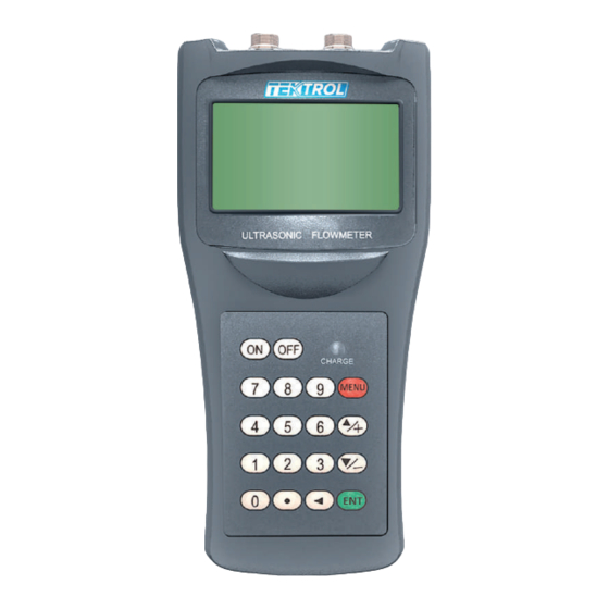
Page 12: Dimensional Drawings
Dimensions 1.77”x1.18”x1.18” 2.36”x1.77”x1.77” 7.87” x0.98”x0.98” 11.02”x1.57”x1.57” Weight 75 g 260 g 250 g 1080 g 2.4 Dimensional Drawings 2.4.1 System Drawings Fig 2: Top View of 1200A-100H Handheld Ultrasonic Flow Meter Fig 3: Front View of 1200A-100H Handheld Ultrasonic Flow Meter www.tek-trol.com... - Page 13 Fig 4: Bottom View of 1200A-100H Handheld Ultrasonic Flow Meter Fig 5: Cables of 1200A-100H Handheld Ultrasonic Flow Meter Mains Adaptor Fig 6: Mains Adaptor of 1200A-100H Handheld Ultrasonic Flow Meter www.tek-trol.com...
-
Page 14: System Description
2.4.2 System Description Fig 7: System Description www.tek-trol.com... -
Page 15: Installation
3 Installation This section covers instructions on installation and commissioning. Installation of the device must be carried out by trained; qualified specialists authorized to perform such works. CAUTION • When removing the instrument from hazardous processes, avoid direct contact with the fluid and the meter •... -
Page 16: Clamp On Mounting Bracket Transducer
3.1.2 Clamp on mounting bracket transducer • • • Fig 9: Tek-Clamp 1200A-100H Handheld Ultrasonic Clamp-on mounting bracket transducer 3.2 Requirements for Measuring Flow meter Accuracy • Medium must be conductive. • The pipe should be completely filled with the medium. •... -
Page 17: Installation Condition
3.3 Installation Condition 3.3.1 Sensors 3.3.1.1 Selection Of Sensor Position The first step before installation should be finding a suitable position to place the sensors. This is a requirement for accurate measurement results. Some basic knowledge about the pipes / the plumbing system is necessary. The ideal location would be an infinitely long, straight pipe, whereas there must be no entrapped air (air bubbles) in the liquid. -
Page 18: Sensor Installation
The following should be considered when looking for a good measuring position: 1. Install the sensors on a preferably long, straight pipe filled with the liquid and does not contain any air bubbles. 2. Make sure that the liquid and thus the pipe is not too hot for the sensors. The temperature should be as similar to the room temperature as possible. -
Page 19: Spacing Between The Sensors
3.3.1.3 Spacing Between the Sensors The distance between the upstream and the downstream sensor can be seen in window M25. The window states the inner distance between the two sensors, which you should stick to as accurately as possible. The information in M25, however, must only be considered a coarse adjustment. -
Page 20: Z-Method Installation
Fig 11: V-Method Installation Top View 3.3.2.2 Z-Method Installation Z-method is commonly used when the pipe diameter is above 8” (200mm). Fig 12: Z-Method Installation Fig 13: Z-Method Installation Top View www.tek-trol.com... -
Page 21: W-Method Installation
3.3.2.3 W-method Installation W-method is usually used on plastic pipes with a diameter from 2” (15mm to 50mm). Fig 14: W-Method Installation Fig 15: W-Method Installation Top View www.tek-trol.com... -
Page 22: Electrical Installations
4 Electrical Installations • Please cut off power supply before connecting the device • Check the cable model before connecting the cable. • Follow the procedure for cable into lead collar: - • At first, loosen the gland nut on lead collar and take off blind, secondly, put gland nut and rubber ring on cable, make the cable through lead collar;... -
Page 23: Signal Strength
4.1 Signal Strength • Signal strength indicates the amplitude of receiving ultrasonic signals by a 3-digit number. [000] means there is no signal detected and [999] refers to the maximum signal strength that can be received. • The following methods are recommended to obtain stronger signals: 1. -
Page 24: Key's Function
CAUTION • Make sure the sensor connected to the earth. • Make sure the liquid is still when regulating instruments. • The electrode and the liquid should be in contact for about 48 hours. 4.3.2 Key’s Function • Key’s function in self- testing way Down button cycles through data displayed on “Down”... -
Page 25: Menu
• Correct the password with one of the new passwords that are provided by manufacturer. Finally, press the “Compound” +” Enter” keys to work in Parameters Setting Way. • There are 6 Passwords in design and among them 4 for deferent operators in secret and 2 are fixed passwords for system operation. -
Page 26: Menu Windows
4.3.5 Menu Windows The user interface of this flow meter comprises about 100 different menu windows that are numbered by M00, M01, M02 … M99. There are two methods to get into certain menu window: • Direct jump in. The user can press the MENU key followed by a 2-digit number. For example, the menu window M11 is for setting up pipe outer diameter. -
Page 27: Menu Window List
4.3.6 Menu Window List • M00~M09 windows are suitable for viewing the instantaneous flow rate, net totalizer value, positive totalizer value, negative totalizer value, instantaneous flow velocity, date time, battery voltage and estimated working hours for the battery. • M10~M29 windows have to be used for entering system parameters, such as pipe outer diameter, pipe wall thickness, liquid type, transducer type / model, transducer installation method, etc. -
Page 28: Steps To Configure The Parameters
4.3.7 Steps to Configure the Parameters 1. Pipe outer diameter. 2. Pipe wall thickness. 3. Pipe materials. 4. Linear material and its sound speed and thickness shows half sentence what any linear. 5. For non-standard liquids, the sound speed of the liquid is also needed. 6. -
Page 29: Menu Window Details
The following tips will facilitate the operation of this instrument. • When the current window is one between M00 to M09, pressing a number key x will enter into the M0x window directly. For example, if the current window display is M01, pressing 7 leads to window M07. •... - Page 30 Window for selecting the liner material. Select none for pipes without any liner. Standard liner materials (no need to enter liner sound speed) include: Tar Epoxy Rubber Mortar Polypropylene Polystyle Polystyrene Polyester Polyethylene Ebonite Teflon Window for entering the sound speed of non-standard liner materials Window for entering the liner thickness if there is a liner Window for entering the roughness coefficient of the pipe inner surface Window for selecting fluid type for standard liquids (no need to enter liquid sound...
- Page 31 Turn on or turn off the NEG totalizer 1. Totalizer reset 2. Restore the factory default settings. Press the key followed by the key. Attention, it is recommended to make notes on the parameters before doing the restoration. Manual totalizer used for calibration. Press any key to start and press the key again to stop the totalizer.
- Page 32 Not used Not used Not used Window to set up the frequency range (lower limit and upper limit) for the frequency output. Valid values: 0Hz-9999Hz. Factory default is 1-1001 Hz Window to set up the minimum flow rate which corresponds to the lower frequency limit of the frequency output Window to set up the maximum flow rate which corresponds to the upper frequency limit of the frequency output...
-
Page 33: Troubleshooting
Display the Reynolds number and the pipe factor used by the flow rate measurement program. Note, the pipe factor is rarely used. Not used Not used Command to store the pipe parameters either in the built-in data logger or to the RS-232C serial interface Command to store the diagnostic information either in the built-in data logger or to the RS-232C serial interface... -
Page 34: Measure Flow Disallow
measured fluid may be limited, or the empty threshold of the empty pipe and the range of the empty pipe are incorrectly set. 2. Check if the signal cable is OK or not. 3. Check if the electro-poles are OK or not. 4. -
Page 35: Further Errors And Countermeasures
6.7 Further Errors and Countermeasures Error codes are indicated by a single letter in the lower right corner of the display. However, these only occur in the menus M00, M01, M02, M03, M90 and M08. The following chart shows the error codes and countermeasures. Error code Message in window M08 Reason... -
Page 36: Appendix
7 Appendix 7.1 Tables: Pipe Size 7.1.1 Copper - Standard Pipe Size Charts: Classification: The copper tube is classified into four distinct specifications based on the wall thickness for a specific outside diameter. The tables given underneath are reference dimensions dependent on application: Size / Nom. -
Page 37: Pvc - Standard Pipe Size Charts
Size / Nom. Dia. Nom. Dia. Nom. Wall Max. Working Pressures* (Outside) (Outside) Thickness inch (mm) inch (mm) inch (mm) bar+ (psi) ” (6) ” (6) ” (0.5) 113 (1638) Usage: General ” (8) ” (8) ” (0.5) 98 (1421) purpose ”... -
Page 38: Steel - Standard Pipe Size Charts
8” 8 ⁵⁵/₆₄” 8 ⁷/₈” ⁷/₃₂” ¹⁵/₆₄” ” ⁵/₁₆” ¹¹/₃₂” ” ¹³/₃₂” ²⁹/₆₄” 8” (200) (225.00) (225.60) (5.40) (6.10) (213.80) (7.90) (8.90) (208.50) (10.50) (11.70) (203.10) ” 9 ²⁷/₃₂” 9 ⁷/₈” ²⁹/₆₄” ³³/₆₄” ” (225) (250.00) (250.70) (11.60) (13.00) (225.75) 10”... - Page 39 0.29” (7.1) 0.40” (10.2) 0.07” (1.7) 0.11” (3.2) 0.16” (3.9) 2” (50) 2.375” (60) 0.22” (5.5) 0.35” (8.7) 0.44” (11.1) 0.09” (2.1) 0.12” (3) 0.21” (5.2) ” (65) 2.875” (73) 0.28” (7) 0.38” (9.5) 0.56” (14) 0.09” (2.1) 0.12” (3) 3.500”...
- Page 40 0.88” (22.2) 0.91” (23) 0.14” (3.4) 0.17” (4.2) 0.25” (6.4) 0.31” (7.8) 0.37” (9.3) 10” (250) 10.750” (273) 0.50” (12.7) 0.60” (15) 0.72” (18.3) 0.85” (21.4) 1.00” (25.4) 0.16” (4) 0.18” (4.6) 0.25” (6.4) 0.33” (8.4) 0.38” (9.5) 0.41” (9.5) 12”...
- Page 41 0.50” (12.7) 0.57” (14.3) 0.75” (19) 0.94” (23.8) 1.16” (28.6) 1.38” (34.9) 1.57” (39.7) 1.79” (45.2) 0.19” (4.8) 0.22” (3.9) 0.25” (6.4) 0.38” (9.5) 0.50” (12.7) 0.60” (15) 20” (500) 20.000” (508) 0.82” (20.6) 1.04” (26.2) 1.29” (32.5) 1.50” (38.1) 1.75”...
-
Page 42: Cast Iron Pipe - Standard Pipe Size Charts
0.32” (7.9) 0.38” (9.5) 32” (800) 32.000” (813) 0.50” (12.7) 0.63” (15.9) 0.69” (17.5) 0.35” (8.7) 0.38” (9.5) 34” (850) 34.000” (864) 0.50” (12.7) 0.63” (15.9) 0.69” (17.5) 0.32” (7.9) 0.38” (9.5) 36” (900) 36.000” (914) 0.50” (12.7) 0.63” (15.9) 0.75”... -
Page 43: Ductile Iron Pipe - Standard Pipe Size Charts
Class E Class F Class G Class H Nominal Outer Wall Outer Wall Outer Wall Outer Wall Pipe Size Diameter Thickness Diameter Thickness Diameter Thickness Diameter Thickness In (mm) In (mm) In (mm) In (mm) In (mm) In (mm) In (mm) In (mm) In (mm) 6”... -
Page 44: Tables: Sound Speed
7.2 Tables: Sound Speed 7.2.1 Solids: Sound Speed Data Sound Speed Sound Speed Material Shear Wave (25(d)) Long. Wave (25(d)) ft/s in/us mm/us Steel, 1% Carbon, hardened 10,335 3,150 0.2315 5.88 Carbon Steel 10,598 3,230 0.2319 5.89 Mild Steel 10,614 3,235 0.2319 5.89... -
Page 45: Water: Sound Speed
PVC, CPVC 3,477 1,060 0.0945 2.40 Acrylic 4,690 1,430 0.1075 2.73 Asbestos Cement 0.0866 2.20 Tar Epoxy 0.0787 2.00 Mortar 0.0984 2.50 Rubber 0.00748 1.90 7.2.2 Water: Sound Speed Sound Speed in Water at atmosphere pressure. Unit T (Deg °F) V (ft/s) 32.00 4600.72 77.00... -
Page 46: Liquids: Sound Speed
7.2.3 Liquids: Sound Speed Sound Speed in Liquids All data given at 77°F (25°C) unless otherwise noted Chemical Kinematic v/°C Substance Sound Speed Formula Specific Gravity Viscosity x10-6 /°C ft/s ft2/s m2/s Acetic anhydride 1.082 (68°F) 3,871.4 1,180 8.274 0.769 (22) Acetic acid, anhydride 1.082 (68°F) - Page 47 Carbon Tetrachloride 1.595 (68°F) 3038.1 2.48 6.531 0.607 (33, 35, 47) Carbon tetrafluoride (14) 1.75 (-302°F) 2,871.5 (-238°F) 875.2 (-150°C) 6.61 (Freon 14) Cetane (23) 0.773 (68°F) 4,389.8 1,338 3.71 46.483 4.32 Chloro-Benezene 1.106 4,176.5 1,273 7.768 0.722 1-Chloro-Butane (22,46) 0.887 3,740.2 1,140...
- Page 48 1,2-bis (DiFluoramino) 1.265 3,149.6 Propane (43) 2,2-bis (Difluoromino) 2 1.254 2920 Propane (43) 2,2-Dihydroxydiethyl Ether 1.116 5,2034 1,586 Dihydroxyethane 1.113 5,439.6 1,658 1,3-Dimethyl-Benzene (46) 0.868 (59°F) 4,406.2 (68°F) 1,343 (20°C) 8.059 (59°F) 0.749 (15°C) 1,2-Dimethyl-Benzene 0.897 (68°F) 4,368.4 1,331.5 9.716 (68°F) 0.903 (20°C) (29,46) 1,4-Dimethyl-Benzene (46)
- Page 49 Hexachloro-Cyclopentadiene 1.7180 3,773 1,150 (47) Hexadecane (23) 0.773 (68°F) 4,389.8 1,338 3.71 46.483 (68°F) 4.32 (20°C) Hexalin 0.962 4,770.3 1,454 760.882 (63°F) 70.69 (17°C) Hexane (16,22,23) 0.659 3,648.3 1,112 2.71 4.798 0.446 n-Hexane (29,33) 0.649 (68°F) 3,540 1,079 4.53 2,5Hexanedione 0.729 4,589.9 1,399...
- Page 50 Perfluoro-1-Hepten (47) 1.67 1,912.7 Perfluoro-n-Hexane (47) 1.672 1,666.7 Phene (29,40,41) 0.879 4,284.8 1,306 4.65 7.65 0.711 b-Phenyl Acrolein 1.112 5,098.4 1,554 Phenylamine (41) 1.022 5,377.3 1,639 39.058 3.63 Phenyl Bromide (46) H5Br 1.522 3,838.6 (68°F) 1,170 (20°C) 7.465 0.693 Phenyl chloride 1.106 4,176.5 1,273...
- Page 51 Tetradecane (46) 0.763 (68°F) 4,366.8 (68°F) 1,331 (20°C) 30.773 (68°F) 2.86 (20°C) Tetraethylene Glycol 1.123 5,203.4 1,568 Tetrafluoro-Methane (14) 1.75 (-302°F) 2,871.5 (-238°F) 875.24 (-150°C) 6.61 (Freon14) Tetrahydro-1,4-isoxazine 1.000 4,731 1,442 Toluene (16,52) 0.867 (68°F) 4,357 (68°F) 1,328 (20°C) 4.27 6.929 0.644 o-Toluidine (46)
-
Page 52: Parts Descriptions
8 Parts Descriptions Fig 20: Standard (Without sensors) Fig 21: Customized (With sensor) www.tek-trol.com... - Page 53 Sales: +31 76-2031908 Sales: +971-6526-8344 Support: +1 847-857-6076 Email: tektrol@tek-trol.com www.tek-trol.com Tek-Trol is a fully owned subsidiary of TEKMATION LLC. We o er our customers a comprehensive range of products and solutions for process, power and oil & gas industries. Tek-Trol provides process measurement and control products for Flow, Level, Temperature &...
Need help?
Do you have a question about the TEK-C LAMP 1200A-100H and is the answer not in the manual?
Questions and answers