
Related Manuals for TEKTROL Tek-Flux 1400A Series


Summary of Contents for TEKTROL Tek-Flux 1400A Series
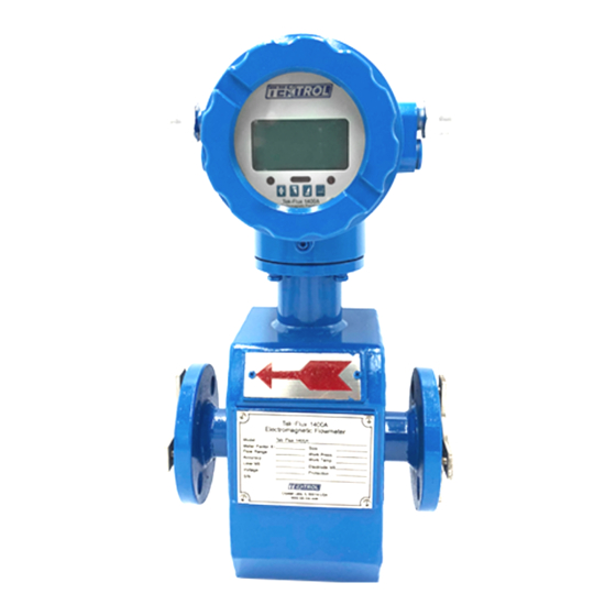
- Page 1 Technology Solutions LUX 1400A Electromagnetic Flow Meter Instruction Manual Document Number: IM-1400A www.tek-trol.com...
- Page 2 www.tek-trol.com NOTICE Read this manual before working with the product. For personal and system safety, and for optimum product performance, make sure you thoroughly understand the contents before installing, using, or maintaining this product. For technical assistance, contact Customer Support 796 Tek-Drive Crystal Lake, IL 60014 Tel: +1 847 857 6076...
-
Page 3: Table Of Contents
Instruction Manual Tek-Flux 1400A Technology Solutions Table of Contents Safety Instructions ....................3 Intended Use ....................... 3 Safety Instructions from the Manufacturer ..............3 1.2.1 Disclaimer .......................... 3 1.2.2 Product Liability and Warranty ..................3 1.2.3 Information Concerning the Documentation ..............3 Safety Precautions ....................... - Page 4 Instruction Manual Tek-Flux 1400A Technology Solutions 5.2.1 Keys’ Function ......................... 24 5.2.2 Keys for Selecting Menu ....................25 5.2.3 Menu ..........................25 Troubleshooting ...................... 28 No Display ......................... 28 Exciting Alarm ......................28 Empty Pipe Alarm ...................... 28 Measure Flow Disallow ....................28 www.tek-trol.com...
-
Page 5: Safety Instructions
Instruction Manual Tek-Flux 1400A Technology Solutions 1 Safety Instructions 1.1 Intended Use Tek-Flux 1400A is used to measure flow rate of electrically conductive liquids. Typical applications are found in all industries e.g. Metallurgy industry, Water and waste water, Agriculture and irrigation, Food and beverage industry, Pharmaceutical industry. 1.2 Safety Instructions from the Manufacturer 1.2.1 Disclaimer The manufacturer will not be held accountable for any damage that happens by using... -
Page 6: Packaging, Transportation And Storage
Instruction Manual Tek-Flux 1400A Technology Solutions Warnings and Symbols Used The following safety symbol marks are used in this operation manual and on the instrument. WARNING Indicates a potentially hazardous situation which, if not avoided, could result in death or serious injury CAUTION Indicates a potentially hazardous situation which, if not avoided, may result in minor or moderate injury. -
Page 7: Transportation
Instruction Manual Tek-Flux 1400A Technology Solutions 1.4.2 Transportation • Avoid impact shocks to the device and prevent it from getting wet during transportation. • Verify local safety regulations, directives, and company procedures with respect to hoisting, rigging, and transportation of heavy equipment. •... -
Page 8: Nameplate
Instruction Manual Tek-Flux 1400A Technology Solutions 1.4.4 Nameplate The nameplate lists the order number and other important information, such as design details and technical data NOTE Check the device nameplate to ensure that the device is delivered according to your order. Check for the correct supply voltage printed on the nameplate. www.tek-trol.com... -
Page 9: Product Description
Instruction Manual Tek-Flux 1400A Technology Solutions 2 Product Description This section covers the reference and specification data, as well as ordering information. 2.1 Introduction Electromagnetic flow meters are also called as Magmeters. They are non-contact instruments used for measuring the volumetric flow rates of any fluids that can adequately conduct electricity in closed pipelines. -
Page 10: Specifications
Instruction Manual Tek-Flux 1400A Technology Solutions Operation of an Electromagnetic Flow Meter 2.3 Specifications 2.3.1 Technical Accuracy ±0.5% Repeatability 0.15% Sensor (Remote Type) to 158 (-20℃ to +70℃) °F °F Ambient Converter to 158 (-20℃ to +70℃) °F °F temperature Integral Type to 122 (-10℃... -
Page 11: Electrode Material Selection
Instruction Manual Tek-Flux 1400A Technology Solutions 2.3.2 Electrode Material Selection Electrode Material Application Used for measuring water, wastewater, inorganic acid, organic 316SS acid or another corrosive medium. Used for measuring oxidizing acid such as nitric acid, mixed acid, and vitriol mixed liquid, also oxydic salt such as Fe++, Hastelloy-C Cu++, other oxidizing agent such as pypocholoride solution whose temperature is higher than normal and seawater. -
Page 12: Dimensional Drawings
Instruction Manual Tek-Flux 1400A Technology Solutions 2.4 Dimensional Drawings 5 3⁄₄" (142.5mm) 9 ½" (235mm) 6 ½" (165mm) Integral Type (≥4") Separate Type (≥4”) Direct Mount Transmitter Outline Dimension of Medium and High Pressure Sensors Sensor(½" to 3") Sensor (½"to 3") Flange connection Size in... -
Page 13: Model Chart
Instruction Manual Tek-Flux 1400A Technology Solutions 2.5 Model Chart Example Tek-Flux 1400A Tek-Flux 1400A-25-1-I-HC-1-1-T-EA Series Tek-Flux 1400A Electromagnetic Flow meter 1/2" (Only PTFE Liner / HC Electrodes) 1" (Only PTFE Liner / HC Electrodes) 1 1/2” (Only PTFE Liner / HC Electrodes) 2"... -
Page 14: Installation
Instruction Manual Tek-Flux 1400A Technology Solutions 3 Installation This section covers instructions on installation and commissioning. Installation of the device must be carried out by trained, qualified specialists authorized to perform such works. CAUTION • When removing the instrument from hazardous processes, avoid direct contact with the fluid and the meter •... -
Page 15: Requirements For Measuring Flow Meter Accuracy
Instruction Manual Tek-Flux 1400A Technology Solutions At flow meter upstream, there should be straight pipe no less than 5D and no less than 2D at flow meter downstream. (D is the inner diameter of the flow meter) 3.2 Requirements for Measuring Flow Meter Accuracy •... - Page 16 Instruction Manual Tek-Flux 1400A Technology Solutions • Install flow meter at the rising pipe • For installing at open pipe, flow meter should be installed at relative low. If the fall in the pipe is more than 5m, vent valve should be installed at the sensor downstream where it should have back pressure •...
-
Page 17: Electrical Installations
Instruction Manual Tek-Flux 1400A Technology Solutions • Flow meter installation in a measuring well: 1. Inlet 5. Flow Meter 2. Entrance Gate 6. Nozzle Stub 3. Cleaning Hole 7. Outlet 4. Overflow Pipe 8. Drain Valve 4 Electrical Installations 4.1 Safety Instruction •... -
Page 18: Grounding Mode
Instruction Manual Tek-Flux 1400A Technology Solutions 4.2.2 Grounding Mode If flow meter is installed in metal pipeline, there should be no insulating coating on pipeline in wall. • If flow meter is installed in the pipeline with insulating paint, the inner part of the grounding ring should be painted on both the sides of the sensor. -
Page 19: Power Supply Wiring
Instruction Manual Tek-Flux 1400A Technology Solutions 4.3.2 Power Supply Wiring • Wiring for direct mount transmitter The above figure shows the wiring terminal board of a Direct Mounted Transmitter Output Current for Flow Measurement Output Current (Ground) for Flow Measurement Frequency (Pulse) Output for Bi-directional Flow Frequency (Pulse) Output (Ground) Alarm Output for Low Limit... - Page 20 Instruction Manual Tek-Flux 1400A Technology Solutions • Wiring for remote type transmitter SIG1 Signal1 SGND Signal Ground SIG2 Signal2 To the mounting sensor Shielded Exciting1 Shielded Exciting2 EXT+ Exciting Current+ EXT- Exciting Current- VDIN Current Two lines 24V Spots Analog Current Output ICOUT Analog Current Output ICCOM...
-
Page 21: Connection Of Cable
Instruction Manual Tek-Flux 1400A Technology Solutions CAUTION Cable should be no more than 328 ft to prevent accuracy and interference. transmitter should be installed closely to sensor as much as possible. NOTE For remote type flow meter, when flow conductivity is more than 50μS/cm, flow signal cable should be shield signal cable with polyvinyl chloride jacket and metal net;... -
Page 22: Digital Output
Instruction Manual Tek-Flux 1400A Technology Solutions 4.5 Digital Output The transmitter has two output signals: frequency and pulse output. The user can choose only one type of output. 4.5.1 Frequency Output Frequency output range is 0 to 5000Hz, and corresponding the percent of flux. ��������������������������������... -
Page 23: Pulse Output Mode
Instruction Manual Tek-Flux 1400A Technology Solutions 4.5.2 Pulse Output Mode The pulse output mainly applies in count mode. A pulse output delegates a unit flux, such as 1l or 1m etc. The pulse output unit divides into 0.001l, 0.01l, 0.1l, 1l, 0.001m 0.01m , 0.1m , 1m... -
Page 24: Digital Output Connection As Relay
Instruction Manual Tek-Flux 1400A Technology Solutions 4.5.5 Digital Output Connection as Relay Commonly, the relay needs E as 12V or 24V. D is an extended diode, most middle relays now have this diode inside. If not have, the user can connect one outside. 4.6 Simulation Signal Output and Calculation 4.6.1 Simulation Signal Output There are two signal systems: 0 to 10 mA and 4 to 20 mA. -
Page 25: Transmitter Connection Of Current Output
Instruction Manual Tek-Flux 1400A Technology Solutions • The Full-Scale Current is Correct Select “Analog Range” to enter. Adjust the converter parameter and make sure the ampere meter is 20 mA (±0.004 mA). Adjust the current between zero and full range, the current function of the converter should reach exactness. -
Page 26: Operation
Instruction Manual Tek-Flux 1400A Technology Solutions 5 Operation This section covers operation techniques and guidelines. 5.1 Key and Display 1. Direct mount transmitter keys and LCD screen display 5.2 Parameter Setting CAUTION • Make sure the sensor connected to the earth •... - Page 27 Instruction Manual Tek-Flux 1400A Technology Solutions NOTE When using the “Compound” key, you should press “Compound” key and “Up” key both or “Compound” key and “Down” key both. To select the zero correction about the flow directly use “Down” or “Up” to Switch. To set or correct working parameters, the converter should be running in Parameters Setting Way instead of Measuring Status.
- Page 28 Instruction Manual Tek-Flux 1400A Technology Solutions • Grade 2 of password (set by manufacturer as 03210): Users can change parameters codes 1 to 25. • Grade 3 of password (set by manufacturer as 06108): Users can change parameters codes 1 to 26 and 35 to 37. •...
- Page 29 Instruction Manual Tek-Flux 1400A Technology Solutions Code Parameter Setting Grades Range Clr Sum Key Set Count 0 to 99999 Snsr Code1 User Set Finished Y/M Snsr Code2 User Set Product number Field Type Select Type1,2,3 Sensor Fact Set Count 0.0000 to 5.9999 Fwd Total Lo Correctable 00000 to 99999...
- Page 30 Instruction Manual Tek-Flux 1400A Technology Solutions 6 Troubleshooting This section provides troubleshooting techniques for most common operating problems. 6.1 No Display 1. Check the power supply connection 2. Check the power fuse for faults 3. Check the contrast of LCD and adjust 6.2 Exciting Alarm 1.
- Page 31 Sales: +31 76-2031908 Sales: +971-6526-8344 Support: +1 847-857-6076 Email: tektrol@tek-trol.com www.tek-trol.com Tek-Trol is a fully owned subsidiary of TEKMATION LLC. We o er our customers a comprehensive range of products and solutions for process, power and oil & gas industries. Tek-Trol provides process measurement and control products for Flow, Level, Temperature &...
Need help?
Do you have a question about the Tek-Flux 1400A Series and is the answer not in the manual?
Questions and answers