
Related Manuals for TEKTROL Tek-Flux 1400A


Summary of Contents for TEKTROL Tek-Flux 1400A
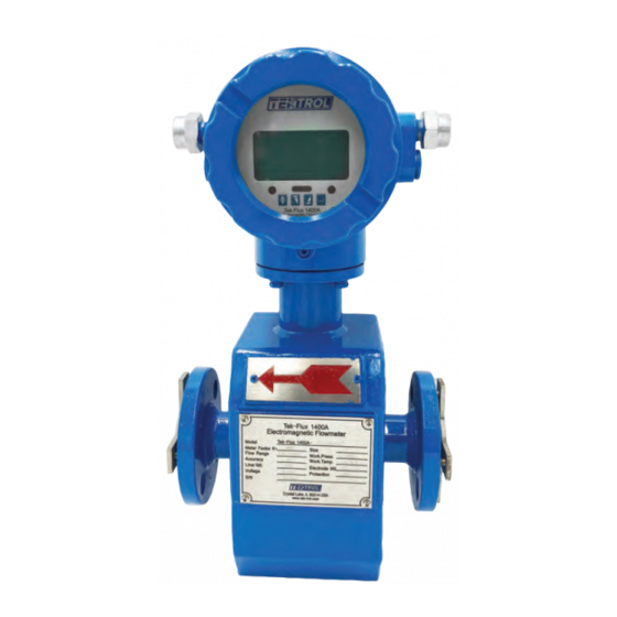
- Page 1 Technology Solutions LUX 1400A Electromagnetic Flow Meter Instruction Manual Document Number: IM-1400A www.tek-trol.com...
- Page 2 www.tek-trol.com NOTICE Read this manual before working with the product. For personal and system safety, and for optimum product performance, make sure you thoroughly understand the contents before installing, using, or maintaining this product. For technical assistance, contact Customer Support 796 Tek-Drive Crystal Lake, IL 60014 Tel: +1 847 857 6076, +1 847 655 7428...
-
Page 3: Table Of Contents
Table of Contents Safety Instructions ......................3 Intended Use .......................... 3 Safety Instructions from the Manufacturer ................3 1.2.1 Disclaimer........................... 3 1.2.2 Product Liability and Warranty ................... 3 1.2.3 Information Concerning the Documentation............... 3 Safety Precautions ......................... 4 Packaging, Transportation and Storage.................. 5 1.4.1 Packaging ........................... - Page 4 4.6.2 Simulation Signal Output Adjust ..................27 4.6.3 Transmitter Connection of Current Output ............... 28 Operation .........................29 Key and Display ........................29 Parameter Setting ........................ 29 5.2.1 Keys’ Function ........................30 5.2.2 Keys for Selecting Menu ....................31 5.2.3 Menu..........................31 Troubleshooting........................34 No Display ..........................
-
Page 5: Safety Instructions
1 Safety Instructions 1.1 Intended Use Tek-Flux 1400A is used to measure flowrate of electrically conductive liquids. Typical applications are found in all industries e.g. Metallurgy industry, Water and wastewater, Agriculture and irrigation, Food and beverage industry, Pharmaceutical industry. 1.2 Safety Instructions from the Manufacturer 1.2.1 Disclaimer... -
Page 6: Safety Precautions
1.3 Safety Precautions You must read these instructions carefully prior to installing and commissioning the device. These instructions are an important part of the product and must be kept for future reference. Only by observing these instructions, optimum protection of both personnel and the environment, as well as safe and fault-free operation of the device can be ensured. -
Page 7: Packaging, Transportation And Storage
1.4 Packaging, Transportation and Storage 1.4.1 Packaging The original package consists of 1. Tek-Flux 1400A Electromagnetic Flow meter 2. Documentation NOTE Unpack and check the contents for damages or signs of rough handling. Report damage to the manufacturer immediately. Check the contents against the packing list provided. -
Page 8: Storage
1.4.3 Storage If this product is to be stored for a long period of time before installation, take the following precautions: • Store your product in the manufacturer’s original packing used for shipping. • Storage location should conform to the following requirements: Free from rain and water Free from vibration and impact shock At room temperature with minimal temperature and humidity variation... -
Page 9: Product Description
2.2 Measuring Principle The Tek-Flux 1400A Electromagnetic flow meter operates on the principle of Faraday’s Law of Induction. According to this principle, any change in the magnetic flux linked to an electric circuit causes an electromotive force (or voltage) to be induced in this circuit. - Page 10 Since the magnetic flux density and the distance between the electrodes remain constant, the induced voltage is directly proportional to the conductor velocity. The value of the velocity is used to calculate the volumetric flow rate as follows: Q = A x v Where, Q = Flow Rate A = Area...
-
Page 11: Specifications
2.3 Specifications 2.3.1 Technical Accuracy ±0.5% Repeatability 0.15% Sensor (Remote Type) -4 to 158 (-20℃ to +70℃) °F °F Ambient Converter to 158 (-20℃ to +70℃) °F °F temperature Integral Type to 122 (-10℃ to +50℃) °F °F Humidity 5% to 95% RH(no frost) Vibration Frequency 55Hz Amplitude... -
Page 12: Lining Material
2.3.3 Lining Material Lining Main performance Application scope material • -112° to 248° Stable chemical performance, Highly corrosive medium resists acid, alkali, saline such as concentrated acid solution and organic solvent. • and concentrated alkaline Does not resist the corrosion of PTFE chlorine trifluoride,... -
Page 13: Flow Range And Nominal Diameter Selection
2.3.4 Flow Range and Nominal Diameter Selection Velocity Inch(ft) 0.98 to 32.80 ft/sec 0.3 to 10 m/s gal/min ½" (0.04) 0.8 to 28.2 0.19 to 0.64 1" (0.08) 2.4 to 77.9 0.53 to 17.7 2" (0.16) 9.4 to 312.6 2.13 to 71.0 3"... -
Page 14: Dimensional Drawings
2.4 Dimensional Drawings Size in Flange Net weight Inches connection in kg (lb) Sensor dimensions in inches (mm) dimension (ft) in Inches ½" (0.04) 7.87" (0.65) 5.11" (0.42) 8.66" (0.72) 4-Φ.62" 17.63 (8) 1" (0.08) 7.87" (0.65) 5.59" (0.46) 9.05" (0.75) 4-Φ.62"... -
Page 15: Model Chart
2.5 Model Chart Note: Please note that when ordering a PTFE lined meter that grounding rings are included and do not have an additional cost... -
Page 16: Installation
3 Installation This section covers instructions on installation and commissioning. Installation of the device must be carried out by trained, qualified specialists authorized to perform such works. CAUTION • When removing the instrument from hazardous processes, avoid direct contact with the fluid and the meter •... -
Page 17: Requirements For Measuring Flow Meter Accuracy
3.2 Requirements for Measuring Flow meter Accuracy • Medium must be conductive. • The pipe should be completely filled with the medium. • Medium conductivity should be homogeneous to avoid severe disruption. If chemical substances need be injected into the pipe, the injection should be operated at upstream side of flow meter;... - Page 18 • Install flow meter at the rising pipe • For installing at open pipe, flow meter should be installed at relative low. If the fall in the pipe is more than 5m, vent valve should be installed at the sensor downstream where it should have back pressure •...
- Page 19 • Flow meter installation in a measuring well: 1. Inlet 5. Flow meter 2. Entrance gate 6. Nozzle stub 3. Cleaning hole 7. Outlet 4. Overflow pipe 8. Drain Valve...
-
Page 20: Electrical Installations
• When wire stripping, do not damage insulating layer which should be reserved. 4.2 Grounding Grounding of Tek-Flux 1400A is very important. Bad grounding will result in abnormal operation. Flow meter sensor part should have separate grounding cable (whose sectional area of copper core should be 1.6mm... -
Page 21: Grounding Mode
4.2.2 Grounding Mode If flow meter is installed in metal pipeline, there should be no insulating coating on pipeline in wall. If flow meter is installed in the pipeline with insulating paint, the inner part of the grounding ring should be painted on both the sides of the sensor. -
Page 22: Transmitter Connections
4.3 Transmitter Connections 4.3.1 Basic Circuit of the Transmitter The converter can supply the exciting current to the coil in the sensor of electromagnetic flow meter; the head amplifier amplifies the electromotive force from the sensor and converts it into standard signals of current or frequency so that the signals can be used for displaying, controlling, and processing. -
Page 23: Power Supply Wiring
4.3.2 Power Supply wiring • Wiring for direct mount transmitter Output Current for Flow Measurement Output Current (Ground) for Flow Measurement Frequency (Pulse) Output for Bi-directional Flow Frequency (Pulse) Output (Ground) Alarm Output for Low Limit Alarm Output for Upper Limit Alarm Output (Ground) FUSE Fuse for Power Supply... - Page 24 • Wiring for remote type transmitter SIG1 Signal1 SGND Signal Ground SIG2 Signal2 To the mounting sensor Shielded Exciting1 Shielded Exciting2 EXT+ Exciting Current+ EXT- Exciting Current- VDIN Current Two lines 24V Spots Analog Current Output ICOUT Analog Current Output ICCOM Analog Current Output Ground POUT...
- Page 25 • Signal cable connection for Direct Mounted Transmitter Double-wire cable (for exciting the current): Power supply for exciting coil three-wire cable: 1. Connected to “Signals 1” 2. Connected to “Signals 2” 3. Shielded Conductor connected to “Signal Ground”...
-
Page 26: Connection Of Cable
4.4 Connection of Cable 4.4.1 Output and Power Cable All cables for signal transferring and for the power supply must be prepared by users. However, care must be taken to choose the cables that meet the upper limit load of consuming current. -
Page 27: Digital Output
4.5 Digital Output The transmitter has two output signals: frequency and pulse output. The user can choose only one type of output. 4.5.1 Frequency Output Frequency output range is 0 to 5000Hz and corresponding the percent of flux. ���������������� ���������� ��... -
Page 28: Digital Output Connection As Photoelectric Coupling (Plc Etc.)
4.5.4 Digital Output Connection as Photoelectric Coupling (PLC etc.) Commonly, the user’s photoelectric coupling current is about 10 mA, so E/R=10 mA, where E=5 to 24V. 4.5.5 Digital Output Connection as Relay Commonly, the relay needs E as 12V or 24V. D is an extended diode, most middle relays now have this diode inside. -
Page 29: Simulation Signal Output And Calculation
4.6 Simulation Signal Output and Calculation 4.6.1 Simulation Signal Output There are two signal systems: 0 to 10 mA and 4 to 20 mA. The user can select from the parameter setting. The inner simulation signal output is 24V under 0 to 20 mA. It can drive 750٠resistance. The percent flux of simulation signal output is: ����������������... -
Page 30: Transmitter Connection Of Current Output
4.6.3 Transmitter Connection of Current Output... -
Page 31: Operation
5 Operation This section covers operation techniques and guidelines. 5.1 Key and Display 1. Direct mount transmitter keys and LCD screen display 5.2 Parameter Setting CAUTION • Make sure the sensor connected to the earth • Make sure the liquid is still when regulating zero of the instruments •... -
Page 32: Keys' Function
5.2.1 Keys’ Function • Keys’ function in self- testing way “Down” key Down button cycles through data displayed on lower lines “Up” key Up button cycles through data displayed on lower lines “Enter” key Press it to come into the interface measuring “Compound”... -
Page 33: Keys For Selecting Menu
Input password. Press “Compound” + “Enter” key. This function lets the user access Parameters Setting status. Need to enter parameter code. • Menu There are 46 parameters of Tek-Flux 1400A, user can set every parameter. The List of Parameters is shown below: 5.2.3 Menu Parameters of converters can decide the running status, process and output ways as well as state of output. - Page 34 Password Grade 5 can be set by skilled users. Grade 4 is mainly used for resetting total volume in password. Grades 1 to 3 can be set by anyone. There are 46 parameters of Tek-Flux 1400A, user can set every parameter. The list of parameters is as shown below:...
- Page 35 Snsr Code1 User Set Finished Y/M Snsr Code2 User Set Product number Field Type Select Type1,2,3 Sensor Fact Set Count 0.0000 to 5.9999 Fwd Total Lo Correctable 00000 to 99999 FwdTotal Hi Correctable 00000 to 9999 RevTotal Lo Correctable 00000 to 99999 RevTotal Hi Correctable 00000 to 9999...
-
Page 36: Troubleshooting
6 Troubleshooting This section provides troubleshooting techniques for most common operating problems. 6.1 No Display 1. Check the power supply connection 2. Check the power fuse for faults 3. Check the contrast of LCD and adjust 6.2 Exciting Alarm 1. Check the connection of the exciting cables 2. - Page 37 796 Tek Drive Crystal Lake, IL 60014 USA Tel.: +1 847 857 6076 , +1 847 655 7428 Fax: +1 847 655 6147 Email: tektrol@tek-trol.com www.tek-trol.com Flow | Level | Temperature | Pressure | Valves | Analyzers | Accessories | TekValSys...
Need help?
Do you have a question about the Tek-Flux 1400A and is the answer not in the manual?
Questions and answers