
Related Manuals for TEKTROL TEK-CLAMP 1200A


Summary of Contents for TEKTROL TEK-CLAMP 1200A
- Page 1 Technology Solutions LAMP 1200A Ultrasonic Clamp-On Flow Meter Instruction Manual Document Number: IM-1200A GlobalTestSupply www. .com Find Quality Products Online at: sales@GlobalTestSupply.com...
- Page 2 NOTICE Read this manual before working with the product. For personal and system safety, and for optimum product performance, make sure you thoroughly understand the contents before installing, using, or maintaining this product. For technical assistance, contact © COPYRIGHT Tek-Trol LLC 2021 No part of this publication may be copied or distributed, transmitted, transcribed, stored in a retrieval system, or translated into any human or computer language, in any form or by any means, electronic, mechanical, manual, or otherwise, or disclosed to third parties without the express...
-
Page 3: Table Of Contents
Table of Contents Safety Instructions ....................3 Intended Use ....................... 3 Safety Instructions from the Manufacturer ..............3 Disclaimer .......................... 3 Product Liability and Warranty ..................4 Information Concerning the Documentation ..............4 Safety Precautions ....................... 4 Packaging, Transportation and Storage ................. 5 Packaging ........................... - Page 4 Menu Window Details....................32 Work parameter solidification of the Flow meter and option indication ...... 36 Zero-Point Setup and Zero-Point Solidification ............36 Factory Use of the Scaling Factor Solidification ............37 Analog Calculating Function Application ..............37 Analogue Input Interface as Digital Input Interface: Method and Introduction ..... 37 Introduction of Serial Peripheral Extension Interface ..........
-
Page 5: Safety Instructions
1 Safety Instructions 1.1 Intended Use Tek-Clamp 1200A is an Ultrasonic Clamp-on Flow meter are used only for measuring the flow of liquids in closed pipes, e.g.: clean water, wastewater etc. The manufacturer is not liable for damage caused by improper or non-designated use. -
Page 6: Product Liability And Warranty
The manufacturer has the right to modify the content of this document, including the disclaimer, at any time for any reason without prior notice, and will not be answerable in any way for the possible consequence of such changes. Product Liability and Warranty The operator shall bear authority for the suitability of the device for the specific application. -
Page 7: Packaging, Transportation And Storage
• Transport the product to the installation site using the original manufacturer’s packing whenever possible. Storage The Tek-Clamp 1200A-100 is designed for installation and usage purpose in typical commercial/industrial environments. The following considerations must be observed in selecting a location for the meter: •... -
Page 8: Nameplate
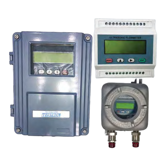
2.1 Introduction Tek-Clamp 1200A Ultrasonic Clamp-on Flow meter is designed to measure the velocity of liquid in a full/closed pipe. It operates according to the difference in the Transit Time of Flight measured and determines the flow velocity by measuring the travel time of a pulse from one transducer to the next. - Page 9 Fig 1: Tek-Clamp 1200A-100H Handheld Ultrasonic Flow Meter The Tek-Clamp 1200A-100H has been developed to measure the flow velocity of liquids in pipes. The non-contact transducers/sensors are placed on the pipes and thus not subject to wear and tear.
-
Page 10: Specifications
Less than 1.5W Environment Temperature -22 °F to 176 °F (-30 °C to 80 °C) Environment Humidity 85% RH IP65 (Tek-Clamp 1200A-100F1) Protection Class IP65; Class I Div II (Tek-Clamp 1200A-100EXP) GlobalTestSupply www. .com Find Quality Products Online at: sales@GlobalTestSupply.com... -
Page 11: Dimensional Drawing Of Tek-Sonic 1200A-100F1
S2-type: for pipe size ½” to 4” M2-type: for pipe size 2” to 28” Clamp-On 1200A-L2: 12” to 200” 1200A-IM: 3” to 7” 1200A-IL: 3” to 12” Protection Class IP68, can work in water with depths less than 10’ (3m) Virtually all commonly used clean liquids. -
Page 12: Dimensional Drawing Of Tek-Sonic 1200A-100F1 S2 & M2 Sensor
Dimensional Drawing of Tek-Sonic 1200A-100F1 S2 & M2 Sensor S2 Sensor M2 Sensor Fig 3: S2 or M2 Sensor 2.5 Dimensional Drawing of Tek-Sonic 1200A-100EXP Fig 4: Tek-Sonic 1200A-100EXP GlobalTestSupply www. .com Find Quality Products Online at: sales@GlobalTestSupply.com... -
Page 13: Model Chart
Fig 5: Tek-Sonic 1200A-100EXP 2.6 Model Chart Model Number Description Note: Controller, Sensors, and Options are all ordered individually Controllers 1200A-100F1 Wall Mount Ultrasonic Flow Meter 1200A-100M Low-Cost DIN Mount Flow Meter 1200A-100EXP Explosion Proof Ultrasonic Flow Meter 1200A-100H Handheld Ultrasonic Flow Meter (with carrying case) Transducers 1200A-S2 ½”... -
Page 14: Installation
For example: Do not install the Tek-Clamp 1200A-100F1 flow meter where it will be difficult for the personnel to perform periodic maintenance. -
Page 15: Installation Of The Transducer
3.3 Installation of the Transducer Installation of Tek-Clamp 1200A-100 series is the easiest and convenient way in the installation of all flow meters. Just choose a suitable measurement point, input the pipe parameters of this pipe point to the flow meter, and then fix the transducers on the pipe. -
Page 16: Sensor Installation
3.3.1.2 Sensor Installation The Tek-Clamp 1200A-100H has piezoelectric sensors which can transmit and receive ultrasonic waves. The ultrasonic waves pass through the pipe walls, and the liquid allows conclusions about the flow velocity. As the transit time of the ultrasonic pulses is very short, the sensors should be installed as precisely as possible to ensure the highest system accuracy. -
Page 17: Spacing Between The Sensors
• Moreover, you should make sure there is no dust or sand between the pipe and the sensor. To avoid air bubbles from causing measurement errors, place the sensors on the pipe laterally. 3.3.1.3 Spacing Between the Sensors The distance between the upstream and the downstream sensor can be seen in window M25. -
Page 18: Length Of The Straight Pipe
Length of the straight pipe The length of upstream and downstream straight pipe of the ultrasonic transducer should be long enough to ensure accurate measurements. • For 90 bend Fig 5: 90 bend pipe • For Tee bend L≥10D Fig 6: Tee bend pipe GlobalTestSupply www. - Page 19 • For Diffuser L≥10D Fig 7: Diffuser pipe • For Reducer Fig 8: Reducer pipe • For Valve L≥10D Fig 9: Valve GlobalTestSupply www. .com Find Quality Products Online at: sales@GlobalTestSupply.com...
-
Page 20: Transducer Installation Method
• For Pump The figure below shows the installation point of transducers when a pump is used in the pipeline. L≥20D Fig 10: Pump The above figure shows the installation point of transducers when a compressor is used in the pipeline. Transducer Installation Method Before installing, start by cleaning the installation area: remove any rust, paint, and anti-rust layers. - Page 21 Fig 11: Transducer Installation Method NOTE If enough grease is not applied or the transducers are not clamped to the wall tightly, the precision of measurement may be effected. GlobalTestSupply www. .com Find Quality Products Online at: sales@GlobalTestSupply.com...
-
Page 22: Installation Space
3.3.3.1 Installation Space Installation space of the clamp-on type transducer is the inner distance between the two transducers when they are facing each other. After giving the input of the required parameters to the menu of the converter, check the display on the parameter M25 to get the installation space. -
Page 23: Installation Method
3.3.3.2 Installation Method There are two types of the installation methods i.e. the V method and the Z method. • V method Fig 13: V-Method Installation V method is a standard installation method and convenient to use for precise measurement of flow. While installing the two transducers, they’re horizontally aligned. - Page 24 • W method Normally, this type of mounting used when the material of pipe is plastic and had diameter of 10 millimetre to 100 millimetre. for small pipe size like 1/2" ,W & Z type method is more accurate than V & also convenient for installation as it provides better spacing distance than V method.
-
Page 25: Instrument Well Construction Requirements
3.4 Instrument Well Construction Requirements To install transducers in an instrument well, there must be enough installation room and should be convenient for people to stand up and work. Distance between the pipe wall and well wall is at least above 22-inch, width is more than (D+22x2) inch, cement pipe width is more than (D+28x2) inch, and the instrument well axial width L is more than D+48 inch. -
Page 26: Electrical Connections
4 Electrical Connections 4.1 Basic Requirement The flow meter should be connected to the AC or DC power supply. 85VAC to 264VAC Power Consumption: Less than 1.5W 8VDC to 36VDC Power Consumption: Less than 1.5W 4.2 Power Supply and Signal Wiring Diagram of 1200A-100F1 Enclosure Fig 17: Power Supply and Signal Wiring Diagram Fig 18: Power Supply and Signal Wiring Diagram GlobalTestSupply... -
Page 27: Keypad
Keypad • The keypad of the flow meter has 16+2 keys. • Keys 0 ~ 9 and • are keys to enter numbers. • Key ▲/+ is the going UP key when the user wants to go to the upper menu window. It also works as ‘+‘... -
Page 28: Menu Window List
• For option selection windows, the user should first press the ENT key to get into option selection mode. Then, use ▲/+ (Up) ,▼/- (down) or digit key to select the right option. Consequently, press the ENT to make the selection. •... -
Page 29: Power Supply And Signal Wiring Diagram Of 1200A-100M
• M86~M89 windows are useful to configure some parameters about the signal management, such as automatic control, power selection and receive window width • M90~M94 windows are for displaying diagnostic data. Those data are very useful when doing a more accurate measurement. •... - Page 30 Fig 21: Power Supply and Signal Wiring Diagram *Note:- Pulse Output: , 4-20 mA output: Passive(Oct+, Oct-) Active(Ao+,Ao-), Remarks for Pulse Output: External 24VDC with 100 to 1000 Ohms resistor. 24Vdc supply to resistor to OCT+ Connect PLC/multimeter between OCT- and -Ve of power supply. , Remarks for 4-20 mA output: configure parameters on Meter for OCT output Directly...
-
Page 31: Power Supply And Signal Wiring Diagram Of 1200A-100Exp
4.4 Power Supply and Signal Wiring Diagram of 1200A-100EXP Fig 23: Power Supply and Signal Wiring Diagram WARNING • Make sure to connect to ground the power board terminal block 4.5 Transducer Wiring Diagram Fig 24: Transducer Wiring Diagram GlobalTestSupply www. -
Page 32: Installation Check-Up
Signal quality is indicated as the Q value (display on M90) that verifies whether the receiving signal is good or not. Tek-Clamp 1200A-100F1 transmitter uses 00-99 digits to represent signal quality. 00 represents the worst signal, 99 represents the best signal. -
Page 33: Operation
5 Operation The Tek-Clamp 1200A-100F1 Ultrasonic Flow meter can use the 16 keys keyboard monitor, the 16 keys parallel and serial port keyboard which includes: 10-digit keys, 2 up/down arrow keys, 1 menu key (M), 1 enter key, 1 decimal point key and 1 backspace key. -
Page 34: Menu Window Details
5.1 Menu Window Details Menu Window Function Display instant flow rate/net totalizer. Adjust the units in M30- Display instant flow rate/instant flow velocity. Adjust the units in M30-M32 Display instant flow rate/positive totalizer. Adjust the units in M30-M32 Display instant flow rate/negative totalizer. Adjust the units in Flow M30-M32 rate/flow... - Page 35 Printing data flow direction control.by default printing data will flow directly to the thermal printer hanged inside bus. Setup printing data output to outside serial port (RS485 port) AI5 setup Display analogue input AI5(reserved for the Tek-Clamp 1200A GlobalTestSupply www. .com Find Quality Products Online at: sales@GlobalTestSupply.com...
- Page 36 mainboard) Setup of OCT totalizer pulse output, pulse width, range:6 Ms- 1000Ms. Choose current loop mode Corresponding data to output of current loop 4mA or 0mA Corresponding data to output of current loop 20mA Verification of current loop output applied to check whether current loop is normal or not.
- Page 37 window, then it creates an LCD backlit control alarm signal output that is transferred to outside by LCD contrast ratio control setup OCT or relay. Beeper setup options Setup Open Collector Transistor output(OCT) output options Setup relay(OCT2) output options Choose input signal of batch controller Batch controller Day/month/year totalizer, check the flow rate and heat quantity of the totalizers...
-
Page 38: Work Parameter Solidification Of The Flow Meter And Option Indication
• Blue colour means the menus related with heat quantity measurement 5.2 Work parameter solidification of the Flow meter and option indication The new Tek-Clamp 1200A has 3 work parameter areas respectively. They are: Present parameter data block, Solidification parameter data block, and the User pipe parameter data block. -
Page 39: Factory Use Of The Scaling Factor Solidification
5.6 Analogue Input Interface as Digital Input Interface: Method and Introduction The new Tek-Clamp 1200A series’ analogue input interface can work as a digital input interface but note that the loop input current should not be over 20 mA. When outer digital quantity voltage is 5V, you should series connect a 1k resistor in return circuit. -
Page 40: Totalizer Reset
NOTE This function is only used during the first installation. 6 Totalizer reset Totalizer reset: press Menu-37-ENT= take you to totalizer reset menu. by Up & down key select "YES" press ENT. select the type for totalizer want to reset ex: Pos., NEG or Select ALL. -
Page 41: Software Upgrade Service
This section provides troubleshooting techniques for most common operating problems. The Tek-Clamp 1200A shows an error on the corner of the menu window via an identification code in a timely order. All the existing errors are displayed on the parameter M08. Self-diagnosis on hardware is conducted every time the flow meter is powered on. - Page 42 System date and time are Date Time Error Reset date and time wrong Check wiring connections. No No Display. Erratic or Problem with wiring influence of measuring Abnormal Operation normally Input password to unlock • Keypad is locked No Response to Key keyboard, or check wiring •...
-
Page 43: Error Messages After Switching On
• Improper settings for measurement, if current output is not current loop output being used) Frequency Output is • 4-20mA current loop over the set value Check frequency output settings (won’t influence the output overflow 120% (refer to M66-M69). or Confirm if •... -
Page 44: Further Errors And Countermeasures
2. The displayed volume flow is obviously too low or too high: Probably, the volume flow in window M44 has been entered manually. Set this value to “0“. b) Problems with the sensor installation Possibly, the display was set to “0“via M42 despite an existing volume flow. Repeat the zero-point setting and make sure that there is no flow in the pipe. -
Page 45: Appendix
indicates the current work progress (1) No liquid in the (1) Choose a pipe that pipeline contains liquid Empty pipe (2) Setting error in (2) Enter “0” in menu M29 window M29. NOTE • The codes *Q, and *E displayed do not affect measurement. They only mean current loop and frequency output have problems 10 Appendix 10.1 Tables: Pipe Size... -
Page 46: Pvc - Standard Pipe Size Charts
” (54) ” (1.2) 27 (391) 33 (478) 21 (304) ” (66.7) ” (1.2) 20 (290) 27 (391) 17 (246) ” (76.1) ” (1.5) 24 (348) 29 (420) 18 (261) ” (108) ” (1.5) 17 (246) 20 (290) 13 (188) 5 ¼”... -
Page 47: Steel - Standard Pipe Size Charts
7 ¼” 6 ³¹/₃₂” 6 ⁶³/₆₄” ²³/₆₄” ¹³/₃₂” ” (177) (177.10) (177.60) (9.20) (10.30) (157.85) 8” 8 ⁵⁵/₆₄” 8 ⁷/₈” ⁷/₃₂” ¹⁵/₆₄” ” ⁵/₁₆” ¹¹/₃₂” ” ¹³/₃₂” ²⁹/₆₄” 8” (200) (225.00) (225.60) (5.40) (6.10) (213.80) (7.90) (8.90) (208.50) (10.50) (11.70) (203.10) ”... - Page 48 0.16” (3.9) 0.22” (5.5) 0.35” (8.7) 0.44” (11.1) 0.09” (2.1) 0.12” (3) 0.21” (5.2) ” (65) 2.875” (73) 0.28” (7) 0.38” (9.5) 0.56” (14) 0.09” (2.1) 0.12” (3) 0.22” (5.5) 3.500” (89) 3” (75) 0.30” (7.6) 0.44” (11.1) 0.60” (15.2) 0.09”...
- Page 49 0.72” (18.3) 0.85” (21.4) 1.00” (25.4) 0.16” (4) 0.18” (4.6) 0.25” (6.4) 0.33” (8.4) 0.38” (9.5) 0.41” (9.5) 12” (300) 12.750” (324) 0.50” (10.3) 0.57” (14.3) 0.69” (17.5) 0.85” (21.4) 1.00” (25.4) 1.13” (28.6) 0.16” (4) 0.19” (4.8) 0.25” (6.4) 0.32”...
- Page 50 0.82” (20.6) 1.04” (26.2) 1.29” (32.5) 1.50” (38.1) 1.75” (44.4) 1.97” (50) 0.19” (4.8) 0.22” (3.9) 0.25” (6.4) 0.38” (9.5) 0.50” (12.7) 22” (550) 22.000” (559) 0.88” (22.2) 1.13” (28.6) 1.38” (34.9) 1.63” (41.3) 1.88” (41.3) 2.22” (56.3) 0.22” (3.9) 0.25”...
-
Page 51: Cast Iron Pipe - Standard Pipe Size Charts
0.38” (9.5) 48” (1200) 48.000” (1219) 0.05” (1.2) Table: Standard ANSI Pipe Size Data for Carbon Steel and Stainless-Steel Pipe Cast Iron Pipe - Standard Pipe Size Charts: Standard Classes of Cast Iron Pipe Class A Class B Class C Class D Nominal Outer... -
Page 52: Tables: Sound Speed
4” (101.6) 4.80” (121) 0.26” (7) 0.29” (7) 0.32” (8) 0.45” (11) 0.38” (10) 0.41” (10) 6” (152.4) 6.90” (175) 0.25” (6) 0.28” (7) 0.31” (8) 0.34” (7) 0.37” (9) 0.40” (10) 0.43” (11) 8” (203.2) 9.05” (229) 0.27” (7) 0.30”... -
Page 53: Water: Sound Speed
Tungsten,carbide 13,058 3,980 Zinc, rolled 8,005 2,440 0.1642 4.17 Glass, Pyrex 10,761 3,280 0.2209 5.61 Glass, heavy silicate flint 7,808 2,380 Glass, Iight borate crown 9,318 2,840 0.2071 5.26 Nylon 3,772 1,150 0.0945 2.40 Nylon,6-6 3,510 1,070 Polyethylene (LD) 0.0909 2.31 Polyethylene (LD) 1,772... -
Page 54: Liquids: Sound Speed
Liquids: Sound Speed Sound Speed in Liquids All data given at 77°F (25°C) unless otherwise noted Chemical Kinematic Substance Sound Speed Formula Specific Gravity Viscosity x10-6 ft/s ft2/s m2/s Acetic anhydride 1.082 (68°F) 3,871.4 1,180 8.274 0.769 (22) Acetic acid, anhydride 1.082 (68°F) 3,871.4 1,180... - Page 55 1-Chloro-Butane (22,46) 0.887 3,740.2 1,140 5.692 (59°F) 0.529 (15°C) Chloro-DiFluoromethane (3) CHCLF 1.491 (-156.2°F) 2,932.7 (-58°F) 893.9 (-50°C) (Freon 22) Chloroform (47) CHCL 1.489 3,211.9 5.918 0.55 1-Chloro-propane (47) 0.892 3,471.1 1,058 4.067 0.378 Chlorotrifluoromethane (5) C 2,375.3 (-116°F) 724 (-82°C) Cinnamaldehyde 1.112 5,098.4...
- Page 56 Dimethylpentane (47) 0.674 3,487.5 1,063 Dimethylphthalate 4,799.9 1,463 Diiodo-Methane 3.235 3,215.2 Dioxane 1.033 4,514.4 1,376 Dodecane (23) 0.749 4,196.2 1,279 19.368 1.80 1,2Ethanediol 1.113 5,439.6 1,658 Ethanenitrile 0.783 4,232.3 1,290 4.745 0.441 Ethanoic Anhydride (22) 1.082 3,871.4 1,180 8.274 0.769 Ethanol 0.789 3,690...
- Page 57 Lsobutanol 0.81 (68°F) 3,976.4 1,212 lso-Butane 4002 1,219.8 Lsopentane (36) 0.62 (68°F) 3,215.2 3.658 0.34 Lsopropano (46) 0.758 (68°F) 3,838.6 (68°F) 1,170 (20°C) 29.245 2.718 Lsopropyl Alcohol (46) 0.758 (68°F) 3,838.6 (68°F) 1,170 (20°C) 29.245 2.718 Kerosene 0.81 4,343.8 1,324 Ketohexamethylene 0.948 4,668.6...
- Page 58 2-Propanone 0.791 3,851.7 1,174 4.293 0.399 Propene (17,18,35) 0.563 (-55.4°F) 3,159.4 (9°F) 963 (-13°C) n-Propyl-Acetate (22) 4,199 (36°F) 1,280 (2°C) n-Propyl-Alcohol 0.78 (68°F) 4,009.2 (68°F) 1,222 (20°C) 27.427 2.549 Propylchloride (47) 0.892 3,471.1 1,058 4.067 0.378 Propylene (17,18,35) 0.536 (-55.4°F) 3,159.4 (9°F) 963 (-13°C) Pyridne...
- Page 59 d-1,3,3 C10H16O 0.947 4,330.7 1,320 2.367 0.22 -Trimethylnorcamphor Trinitrotoluene (43) 1.64 5,282.2 (178°F) 1,610 (81°C) Turpentine 0.88 4,117.5 1,255 15.064 Unisis800 0.87 4,416 1,346 1.00 Water, Distilled (49,50) 0.996 4,914.7 1,498 10.76 0.695 Water, Sea WoodAlcihol (40,41) 4,593 1,400 Xenon (45) 1.025 5,023 1,531...
Need help?
Do you have a question about the TEK-CLAMP 1200A and is the answer not in the manual?
Questions and answers