
Related Manuals for TEKTROL Tek-LCD 7803A


Summary of Contents for TEKTROL Tek-LCD 7803A
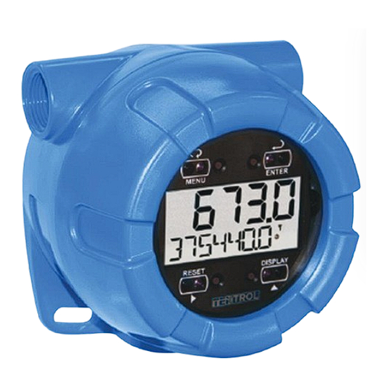
- Page 1 Technology Solutions Tek-LCD 7803A NEMA 4X Pulse Input Flow Rate/Totalizer Indicator Instruction Manual Document Number: IM-7803A www.tek-trol.com...
- Page 2 www.tek-trol.com NOTICE Read this manual before working with the product. For personal and system safety, and for optimum product performance, make sure you thoroughly understand the contents before installing, using, or maintaining this product. For technical assistance, contact Customer Support 796 Tek-Drive Crystal Lake, IL 60014 Tel: +1 847 857 6076, +1 847 655 7428...
-
Page 3: Table Of Contents
Table of Contents Safety Instructions ........................ 5 Installation ..........................5 Unpacking ..........................5 Conduit/Stopping Plug ......................5 Product Description ......................6 Introduction ..........................6 Specifications ..........................6 Mounting..........................11 Mounting Dimensions ......................12 Connections ........................13 3.1.1 Input Signal Connections ....................... 14 3.1.2 DC Power Connection ........................ - Page 4 5.3.10 Custom Tag (TAG) ........................43 5.3.11 Setting the Toggle Time (TIME)....................44 5.3.12 Advanced Features Menu ......................45 5.3.13 Advanced Features Menu & Display Messages ..............50 5.3.14 Pulse Output (PUlse) ........................ 51 5.3.15 Alarm Output (alrm) ......................... 52 5.3.16 Timer Output (tmer).........................
- Page 5 5.6.8 Information (INFO) ........................76 Operation ........................... 77 6.1.1 Front Panel Buttons Operation ....................77 6.1.2 Through-Window Button Operation .................... 77 6.1.3 Through-Window Button Tips and Troubleshooting..............78 Grand Total Reading (GrTOTAL) ....................79 Toggle Lower Display Parameter ..................... 79 Resetting the Total (RESET TOTAL?) ..................
- Page 6 Disclaimer The information contained in this document is subject to change without notice. Tek-Trol makes no representations or warranties with respect to the contents hereof; and specifically disclaims any implied warranties of merchantability or fitness for a particular purpose. WARNING •...
-
Page 7: Safety Instructions
If any part is missing or the meter malfunctions, please contact your supplier or the factory for assistance. 1.3 Conduit/Stopping Plug The Tek-LCD 7803A is provided with three ¾ NPT threaded conduit openings and one IP68 rated ¾ NPT plastic conduit plug. The conduit/stopping plug included has 1.29 wrenching flats and a screwdriver slot. -
Page 8: Product Description
2 Product Description 2.1 Introduction The Tek-LCD 7803A is a plastic field mounted rate/totalizer designed for rugged and demanding applications in harsh environments. It can be programmed using the four through-window buttons, without removing the cover, or with four internal pushbuttons. The top numeric display will read rate or total up to five digits and the alphanumeric bottom display will read up to 7 digits, 13 digits with the total overflow feature. - Page 9 DATA LOGGING Up to 1024 records, recorded 4/day at specific times or at defined time intervals. Record contains date, time, rate, total, grand total, and log number. PASSWORD MENU Three programmable password selections can be used for the following: restrict modification of settings, prevent resetting the total or grand total OPTIONS without the password, or permanently lock out the ability to change or reset the grand total or any grand total related settings (making a...
- Page 10 Rate Input PULSE/ TRANSISTOR/ Field selectable; Sourcing or sinking pulse or square wave CONTACT CLOSURE INPUT 0-5 V, 0-12 V, or 0-24 V; TTL; NPN or PNP transistor; Open collector 100 kΩ pull-up to 3 V; Switch contact 100 kΩ pull-up to 3 V; 0.0001 Hz.
- Page 11 Rate/Totalizer DISPLAY ASSIGNMENT The Top display is assigned to rate or total. The Bottom display is programmable to display total; total and units; total and tag; total, total units, and rate units; grand total; grand total and grand total units; grand total and tag;...
- Page 12 GRAND TOTAL The grand total can display up to 9,999,999,999,999. Up to 9,999,999 can be displayed on the lower display normally. An overflow display will OVERFLOW AND toggle between the first six digits and last seven digits (999999 <> ROLLOVER 9999999) for a 13-digit total.
-
Page 13: Mounting
2.3 Mounting The Tek-LCD 7803A has two slotted mounting flanges that may be used for pipe mounting or wall mounting. Alternatively, the unit may be supported by the conduit using the conduit holes provided. WARNING Do not attempt to loosen or remove flange bolts while the meter is in service. -
Page 14: Mounting Dimensions
2.4 Mounting Dimensions The supplied conduit plug may extend up to 0.21” [0.01ft] from the conduit opening when installed. -
Page 15: Connections
3 Connections WARNING • Static electricity can damage sensitive components. • Observe safe handling precautions for static-sensitive components. • Use proper grounding procedures/codes. • If the meter is installed in a high voltage environment and a fault or installation error occurs, high voltage may be present on any lead or terminal. -
Page 16: Input Signal Connections
Figure 1. Connector Board 3.1.1 Input Signal Connections Signal connections are made to a barrier terminal mounted in the base of the enclosure. Input level and type are configured using the slide switches on the bottom of the display module as shown in the lower right of the following figures Figure 3. - Page 17 Flowmeter INPUT LEVEL ( Magnetic Pickup Coil) Figure 4. Self-Powered Magnetic Pickup Coil Flowmeter (Coil)
- Page 18 Figure 7. Switch Contact Input (Reed)
-
Page 19: Dc Power Connection
3.1.2 DC Power Connection wired as shown in Figure 8. The same power supply may be used to power other circuits including a PNP-type sensor, however to maintain input isolation, a separate power supply must be used to power the Opto-Isolated Flowmeter as shown in Figure 3. Power Supply Figure 8. -
Page 20: Open Collector Output Connections
3.1.4 Open Collector Output Connections Figure 10. Open Collector Output Connections... -
Page 21: Setup And Programming
4 Setup and Programming There is no need to recalibrate the meter for frequency in Hz when first received from the factory. The meter is factory calibrated for Hz prior to shipment. The calibration equipment is certified to NIST standards Overview Setup and programming are done through the infrared through-window buttons or using the mechanical buttons when uncovered. -
Page 22: Through-Window Button Tips And Troubleshooting
WARNING Through-window buttons will not work if two or more buttons are detected as being pressed simultaneously. As a result, be careful to avoid triggering multiple buttons or reaching across IMPORTANT one button location to press another. careful to avoid triggering multiple buttons or reaching across IMPORTANT one button location to press another. -
Page 23: Button And Display
4.3 Button and Display... -
Page 24: Menu Button
4.3.1 Menu Button Hold the Menu SafeTouch® button when in power save mode (display will show ) to awaken • SafeTouch® buttons. Press the Menu button to enter Programming Mode. • Press the Menu button during Programming Mode to return to return to the previous menu •... -
Page 25: Setting Alphanumeric Labels (Label)
Press the Enter button, at any time, to accept a setting or Menu button to exit without saving changes. The decimal point is set using the Right or Up arrow button in the Setup, Decimal Point menu. 4.4 Setting Alphanumeric Labels (LABEL) Fully alphanumeric values are set using the Right button to select the digit, the Up and Right arrow buttons to select the digit reading, and the Enter button to confirm and select the next digit. - Page 26 Press Menu, at any time, to return to the previous menu selection. Press and hold the Menu • button for 1.5 seconds at any time to return to Run Mode. Changes to the settings are saved to memory only after pressing Enter. •...
-
Page 27: Setup Menu Display Functions & Messages
4.6 Setup Menu Display Functions & Messages The meter displays various functions and messages during setup, programming, and operation. The following table shows the main menu functions and messages in the order they appear in the menu. Display Parameter Action/Setting SETUP Setup Enter Setup menu... - Page 28 Display Parameter Action/Setting P/HECtL Pulses/hectoliter Set K-factor in pulses per hectoliter P/CUST Pulses/custom Set K-factor custom unit Dec.pT K-factor decimal point Set the number of decimal points in the K-factor FAcTR K-factor value Set the K-factor for custom units Unit`s Units Select standard units or custom unit/tag TbASE...
- Page 29 Display Parameter Action/Setting factor Tot U Total units Select total display units Nmult Total multiplier Select the total units multiplier x1 (no multiplier) Select no multiplier X100 h x100 (h) Select x100 multiplier with h unit prefix X1000 k x1000 (k) Select x1,000 multiplier with k unit prefix X1.0e6 M x1.0*10...
- Page 30 Display Parameter Action/Setting Grtot Grand total Display grand total GrTOT+U` Grand total & units Display grand total and units GT+TAG Grand total & tag Display the grand total and custom tag GT+U+RU Grand total & units & Display the grand total, grand total units, and rate units rate units rate Rate...
-
Page 31: Setting Up The Meter (Setup)
5 Setting Up the Meter (SETUP) The Setup menu is used to select: Input type selection (INPuT) K-factor number and units (FActr) Display rate, total, and grand total units (Units) Rate and total decimal point position (dec.pt) 5. Select what will appear on the lower display (DSPLY) Press the Enter button to access any menu or press Up arrow button to scroll through choices. -
Page 32: Selecting Input Type (Input)
5.1.1 Selecting Input Type (Input) Seven input types may be set. See Rate Input specifications on page 8 for electrical specifications of the inputs. The following input types may be selected: Active (activ) External power supply driven pulse inputs NPN (NPN) Internal pull-up resistor on S+ for NPN inputs PNP (PNP) Internal pull-down resistor on S+ for PNP inputs... -
Page 34: Entering The K-Factor (Factr)
CAUTION Performing a k-factor operation will override any scaling or calibration programming. Refer to Scaling & Calibration (SCALCAL) for more information on these programming methods. 5.2 Entering the K-Factor (Factr) The meter may be scaled using the K-factor, or conversion factor, function. Most flowmeter manufacturers provide this information with the device. - Page 35 Pressing the Right arrow moves the decimal point one place to the right (including no decimal point). Pressing the Up arrow moves the decimal point one place to the left. K-Factor Value (factr) Enter the K-factor value. This value is entered in Pulses/Unit as defined by the KFactor Units parameter.
-
Page 36: Setting The Time Base (Tbase)
The following units may be selected as the base units for rate, total, and grand total. Time base for rate and a multiplier for total and grand total units may also be selected separately. Units Unit Description Gallons Set units as gallons Liters Set units as liters IGAL... -
Page 37: Setting The Rate Display Units (Rateu)
5.3 Setting the Rate Display Units (rateU) Rate is displayed in terms of a unit of volume, and a time base. The unit selected will be used with the time base to establish the rate unit (example: GAL/S when Units is GAL, and time base is seconds). -
Page 38: Total Units (Tot U)
5.3.1 Total Units (tot U) This menu is used to select the display units for the total. The base unit and a multiplier prefix are selected. If total and units are selected to display, the multiplier prefix will appear before the total unit (example: MGAL, kL). -
Page 39: Grand Total Units (Gtotu)
5.3.2 Grand Total Units (GtotU) This menu is used to select the display units for the grand total. The base unit and a multiplier prefix are selected. If grand total and units are selected to display, the multiplier prefix will appear before the total unit (example: MGAL, kL). -
Page 40: Automatic Unit Conversions
5.3.3 Automatic Unit Conversions When switching from any standard unit of rate, total, or grand total to any other standard unit, automatic unit conversions are performed by the meter. No unit conversions will be performed when the K-Factor Units (FuNiT) menu is set to custom (CUST). -
Page 41: Custom Units Rate Conversion Factor (Ratcf)
When selected for total or grand total, a custom unit will not allow a multiplier prefix. A custom total or grand total unit will allow a total or grand total conversion factor to be entered to define the unit. Fully alphanumeric values are set using the Right button to select the digit to be changed. Press the Up button to begin editing the digit, then the Up and Right arrow buttons to select the next or previous alphanumeric character. -
Page 42: Custom Units Total Conversion Factor (Totcf)
5.3.5 Custom Units Total Conversion Factor (totCF) The total conversion factor is only used when the Units for total have been set to custom (CUST). This menu will not appear if standard display units are selected for total. Total Conversion Factor is used to convert to a custom unit of total display. For example, to display total as quantity of 2.5 gallon containers when the K-Factor units are set to gallons, enter a conversion factor of 2.500. -
Page 43: Configuring The Display (Dsply)
Pressing the Right arrow moves the decimal point one place to the right (including no decimal point). Pressing the Up arrow moves the decimal point one place to the left. 5.3.7 Configuring the Display (Dsply) The top and bottom displays can be independently programmed to display selected information. 5.3.8 Top Display (TOp) The top display can be programmed to display rate or total. -
Page 44: Bottom Display (Botm)
5.3.9 Bottom Display (bOtm) The bottom display can be programmed to display the following information. Total Alternating total and total units Alternating total and custom tag Alternating total, total units, and rate units Grand total Alternating grand total and grand total units Alternating grand total and custom tag Alternating grant total, grand total units, and rate units Rate... -
Page 45: Custom Tag (Tag)
5.3.10 Custom Tag (TAG) When the bottom display selected includes a custom tag, a User menu will then allow a custom tag to be programmed. Any 7-digit 14-segment label may be entered for a custom tag (examples: RATe,... -
Page 46: Setting The Toggle Time (Time)
Fully alphanumeric values are set using the Right button to select the digit, the Up and Right arrow buttons to select the digit reading, and the Enter button to confirm and select the next digit. For details on setting alphanumeric labels, refer to Setting Alphanumeric Labels (LABEL) . 5.3.11 Setting the Toggle Time (TIME) If the bottom display is programmed to toggle (TOGLE), the meter will prompt for a toggle time. -
Page 47: Advanced Features Menu
5.3.12 Advanced Features Menu To simplify the setup process, functions not needed for most applications are located in the Advanced Features menu. Access the Advanced features menu by pressing Enter at the Advance menu in the Main Menu defined. The Advanced menu is used to select: Open collector output configuration (OUTPUT) Gate function for low speed inputs (GATE) Set the input filter (FILTER) - Page 48 Enter the System menu for meter settings and data logging (SYSTEM) Display Parameter Action/Setting ADVANCE Advanced Enter Advanced menu OUTPUT Output Setup open collector outputs Out 1 and Out 2 Output 1 Assign function of open collector output 1 OUT 1 OUT 2 Output 2 Assign function of open collector output 2...
- Page 49 nmed Medium speed filter Set medium speed filter Low speed filter Set low speed filter CUTOFF Low-flow cutoff Enter Low-Low Cutoff menu SCALCAL Scale & calibrate Enter the Scale & Calibrate menu to program without using a k-factor sCalE Scale Enter the Scale menu Calibrate Enter the Calibrate menu...
- Page 50 Pass GT Password grand Enter password to permanently lock out grand total total related parameters and reset UnLOC Unlock Password has been unlocked LOCd Lock Password has been locked UNLOCKD Unlocked Program password to lock meter LOCKED Locked Enter password to unlock meter CUSTOM Custom Enter Custom menu...
- Page 51 ALL ERASE All erase Erase all logs Erase? Erase? Confirm to erase all logs BAKLITE Backlight Enable or disable backlight DsabL Disable Disable backlight EnAbL Enable Enable backlight BACKUP Backup Enter Backup menu SAvE? Save? Save current parameters to backup restore LOad? Load? Load parameters from backup restore...
-
Page 52: Advanced Features Menu & Display Messages
Press the Enter button to access any menu or press Up arrow button to scroll through choices. Press the Menu button to back out of a menu or hold the Menu button to exit at any time. 5.3.13 Advanced Features Menu & Display Messages The following table shows the Advanced features menu functions and messages in the order they appear in the menu. -
Page 53: Pulse Output (Pulse)
Output 1 and 2 Setup (OUT 1, OUT 2) The function of open collector output 1 and 2 is configured using the Off, Pulse, Alarm, and Timer menus detailed below. 5.3.14 Pulse Output (PUlse) Pulse outputs may be assigned to rate, total, grand total, retransmit, quadrature, or test. Rate Pulse Output (rate) A rate-based pulse output is a factor of the rate display and count (output K-factor). -
Page 54: Alarm Output (Alrm)
For example, if the input K-factor value is set to 10, and the count set to 10, one output pulse is generated for every 100 input pulses. Total & Grand Total Pulse Output (Total, Grtot) A total and grand total based pulse output is a factor of the associated total and count (output K-factor). - Page 55 Rate Alarm (rate) Program the rate set point to trigger the alarm. Rate alarm deadband is determined by the difference between set and reset points. Minimum deadband is one display count. If set and reset points are programmed the same, output will reset one count below set point. Total or Grand Total Alarm (Total, Grtot) Program total or grand total set point.
-
Page 56: Timer Output (Tmer)
If the total/grand total is set for manual reset, this alarm will remain until the total/grand total is reset to 0. If automatic total/grand total reset is enabled, the output will generate an alarm for a period of time programmed in ADVANCE T RESET Auto T DELAY. After this time delay, the total/grand total will reset to 0 and the alarm will clear. -
Page 57: Gate Function (Gate)
5.3.18 Gate Function (GATE) The gate function is used for displaying slow pulse rates. Using the programmable gate, the meter is able to display pulse rates as slow as 1 pulse every 9,999 seconds (0.0001 Hz). The gate function can also be used to obtain a steady display reading with a fluctuating input signal. -
Page 58: Undoing K-Factor, Scale, And Calibration (Undo?)
NOTE Performing a scaling or calibration operation will override any k-factor programming. Similarly, completing the k-factor menu will override any scaling or calibration performed on the meter. Verify the method of programming required, use the password protection feature to secure the meter if necessary. There are three methods of programming the display to show the correct engineering units based on input pulses. - Page 59 The pulse input can be scaled to display the process variable in engineering units. A signal source is not needed to scale the meter; simply program the inputs and corresponding display values. A programmed scaled input will work with Automatic Unit. The units for the display values that must be entered are a combination of the programmed Rate Unit and the time unit (Time UNIT) entered in the Scale menu.
-
Page 60: Multi-Point Linearization (Nopts)
5.4.2 Multi-Point Linearization (nopts) Up to 32 linearization points can be selected under the nopts function. The multipoint linearization can be used to linearize the display for non-linear inputs. 5.4.3 Number of Points (nopts) Enter number of linearization points. The default value is 2 points. For linear inputs requiring only 2 scale points, the number of points can be left at 2. -
Page 61: Important Programming Note: Save (Save?)
5.4.8 Important Programming Note: Save (save?) After entering the last display value, the scaling entries must be saved (SAUE?) before they will be put into effect. However, you may move past this selection using the Up-arrow key if you need to go back and correct an earlier entry. -
Page 63: Important Programming Note: Save (Save?)
The multi-point linearization feature (nopts) can be used to linearize the display for non-linear signals. For instructions on how to utilize this feature, see Multi-Point Linearization (nopts). For instructions on how to program numeric values see Setting Numeric Values. Press the Up-arrow button to scroll to the Calibration menu (CAL) and press Enter. The meter displays nopts. -
Page 64: Minimum Input Span
5.4.12 Minimum Input Span The minimum allowed input span is 1 Hz, which is the minimum difference between input 1 and input 2 signals required to complete the calibration or scaling of the meter. 5.4.13 Multi-Point Linearization (nopts) Up to 32 linearization points can be selected under the nopts function. The multipoint linearization can be used to linearize the display for non-linear inputs. -
Page 65: Manual Or Automatic Grand Total Reset Function (Gtrst)
For automatic reset, select T RESET t rst Auto T DELAY and enter reset delay time in seconds. Once the output alarm total set point is reached, the meter waits for a programmed amount of time (T DELAY) and then resets the total to zero. For timed reset, select T RESET ... -
Page 66: Setting Up Passwords (Passwrd)
For timed reset, select T RESET t rst Time T RESET and enter the time of day at which the total should be reset. The total value will be reset every day at the specified time. Press the Enter button, at any time, to accept a setting; otherwise press the Menu button to exit without saving changes. -
Page 67: Locking Meter Setup Parameters
Model: Serial Number: Setting Lockout Password (PASS): __ __ __ __ __ Total Reset Password (PASS T): __ __ __ __ __ Grand Total Reset Password (PASS GT) __ __ __ __ __ 5.5.1 Locking Meter Setup Parameters Enter the Password menu, select Pass, and program a five-digit password. The meter will return to Run Mode after locking any of the passwords. -
Page 68: Disabling Password Protection
The password requirement may be disabled by entering the password in the Password menu for total (Pass T) or grand total (Pass GT). 5.5.5 Disabling Password Protection To disable the password protection, access the Password menu, select the type of password to be disabled, and enter the correct password as shown below. - Page 69 CAUTION Locking the meter into a non-resettable grand total is not reversible. It is a permanent meter configuration. Doing so will permanently prevent most input parameters from being altered. This should be the last step after verifying all setup parameters. Non-resettable grand total password: 50873 Non-Resettable Grand Total Locked Menus &...
-
Page 70: Custom (Custom)
5.6 Custom (CUSTOM) The Custom menu is used to modify the initial programming menus that appear in the Main Menu when the Menu button is pressed in Run Mode. CAUTION Changing the default menu setup with the Custom menu feature may change the setup and operation procedures described in this manual. - Page 71 Custom Menu Parameters Display Parameter/Menu Action NONE None Set no menu position display INPUT Input Set to show Input menu KFACTOR K-Factor Set to show K-Factor menu UNITs Units Select standard units or custom unit/tag DECIMAL Decimal Set to show Decimal menu DISPLAY Display Set to show Display menu...
-
Page 72: System (System)
INTERVL Interval Set interval log times LOGVIEW Log View Enter Log View menu PASSWRD Password Set to show Password menu SETUP Setup Set to show Setup menu ADVANCE Advance Set to show Advanced menu SYSTEM System Set to show System menu 5.6.1 System (SYSTEM) The system function is used to set the real time clock, set daily data log times, enable/disable the backlight, store, restore, and backup restore feature, and review basic system identification... - Page 73 Figure 11. Date Display Example The year, month, day, hour, and minute may all be set by the user. The real time clock will need to be reset if external power is lost. Changing the time (hours and minutes) will reset the seconds clock to 0.
-
Page 74: Data Log Setup (Datalog)
5.6.3 Data Log Setup (DATALOG) The Data Log menu is used to setup and enable the data log functions. The meter may contain up to 1024 records, each containing date, time, rate, total, grand total, and log number. There are two ways to configure the time when a data log is recorded. The Log Time feature allows up to 4 data logs to be recorded each day, at specific times. -
Page 75: Log Time Setup (Logtime)
5.6.4 Log Time Setup (LOGTIME) The Log Time menu contains four log points (LOG 1 to LOG 4). Each log time is configured separately. For each daily log time desired, enable a log, and set the log time for the hours and minutes the log is to be recorded. The time is set in real-time, based on the real time clock setup. - Page 76 Once the log records are displayed, use the Up and Right arrows to change the log entry being viewed. The Enter key changes the displayed information for the same log. The Backlight menu is used to enable or disable the backlight.
-
Page 77: Backup & Restore (Backup)
5.6.7 Backup & Restore (BACKUP) The meter saves all parameter settings and no reprogramming is necessary when power is lost and restored to the meter. The total and grand totals are saved during a power loss. Only the maximum and minimum displays are reset when power is lost. The features are used to save and restore programmed settings. -
Page 78: Information (Info)
The save feature (SAVE?) saves all current parameter settings into the memory of the backup restore. The backup restore feature is loaded with factory default settings until a new configuration is saved. The load feature (load?) restores all parameters to the programmed values stored in backup restore memory. -
Page 79: Operation
6 Operation 6.1.1 Front Panel Buttons Operation Symbol Description Hold the Menu SafeTouch® button when in power save mode (display will show ) to awaken • SafeTouch® buttons. Press the Menu button to enter Programming Mode. • Press the Menu button during Programming Mode to return to return to the previous menu •... -
Page 80: Through-Window Button Tips And Troubleshooting
Through-Window Power Save Mode Through-window buttons enter a power saving mode after three minutes of inactivity. This mode is indicated by a pause symbol ( ) appearing in the lower right of the display. Only the MENU button is monitored in this mode. -
Page 81: Grand Total Reading (Grtotal)
Through-Window Button Equalize Delay The through-window buttons are designed to constantly recalibrate for ambient conditions. When the cover position is changed, the cover is removed, or an object is removed that was placed over the front window, it may take a moment for the through-window buttons to recalibrate to the change in conditions. -
Page 82: Resetting The Total (Reset Total?)
6.4 Resetting the Total (RESET TOTAL?) If manual Total Reset is enabled in the Program menu, the total may be reset by pressing the Reset button and using the Enter button to confirm the reset. Additionally, if programmed for manual reset, the total may be reset using a normally open pushbutton connected across the terminals RST and COM. -
Page 83: Reset Meter To Factory Defaults
6.7 Reset Meter to Factory Defaults Reset to factory defaults will restore most meter parameters to their factory default setting. When the parameters have been changed in a way that is difficult to determine what’s happening, it might be better to start the setup process from the factory defaults. Factory default reset does not change the saved backup restore settings, override passwords, or edit parameters locked by a permanent non-resettable grand total. - Page 84 Parameter Display Default Setting User Setting Scale/Cal # Points nopts 2 (N/A) Scale Unit Funit Pulses/Gallon (N/A) Scale Unit Time Base tinme Second (N/A) Scale/Cal Input 1 Inpt1 00000 (N/A) Scale/Cal Display 1 dspl1 0000.0 (N/A) Scale/Cal Input 2 Inpt2 1000 (N/A) Scale/Cal Display 1 Dspl2...
-
Page 85: Troubleshooting
7 Troubleshooting The rugged design and the user-friendly interface of the meter should make it unusual for the installer or operator to refer to this section of the manual. If the meter is not working as expected, refer to the recommendations below. 7.1 Troubleshooting Tips Symptom Check/Action... -
Page 86: Quick User Interface Reference
8 Quick User Interface Reference Pushbutton Function Menu Go to Programming mode, back out one level of programming. Hold to enter Advanced Features mode. Leave grand total/max/min mode. Right Arrow Move to next digit or decimal point position. Go to reset menu Return to last programming menu. - Page 87 796 Tek Drive Crystal Lake, IL 60014 USA Tel.: +1 847 857 6076 , +1 847 655 7428 Fax: +1 847 655 6147 Email: tektrol@tek-trol.com www.tek-trol.com Flow | Level | Temperature | Pressure | Valves | Analyzers | Accessories | TekValSys...
Need help?
Do you have a question about the Tek-LCD 7803A and is the answer not in the manual?
Questions and answers