Table of Contents
Advertisement
Quick Links
Advertisement
Table of Contents

Related Manuals for sitrex PRO/17


Summary of Contents for sitrex PRO/17
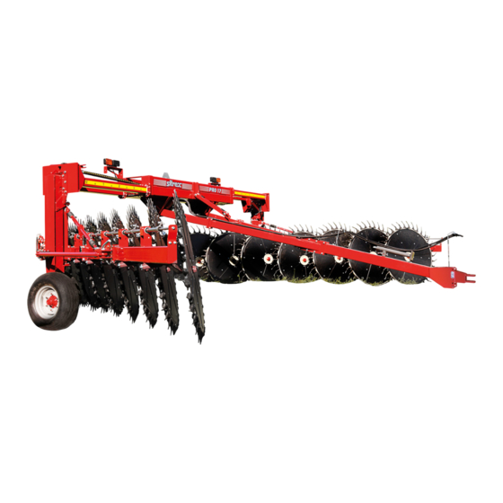
- Page 1 ASSEMBLY, USE AND MAINTENANCE PRO/17 05/2014 (FROM SERIAL NUMBER 247731)
-
Page 2: Warranty
WARRANTY On delivery, check that the machine has not been damaged during transport and that all the attachments are present. Claims must be made in writing to the agent within 8 days of receipt. The manufacturer warrants new machinery at the time of delivery to the original purchaser to be free from defects in material and workmanship if properly set up and operated in accordance with this Operator’s Manual. -
Page 3: Warning Signs
1) GUIDE TO THE SIGNS AND SYMBOLS USED ON THE MACHINE IMPORTANT These signs and symbols give information to the operator on how to make the best use of the machine so as to prolong life, avoid damage, optimise work and, above all, to avoid injury to the operator and anyone within range of the machine. - Page 4 5) Use paper or cardboard to check for and/or clean any leaks from cylinders and oleo dynamic components in general. Never touch with bare hands, as it is harmful to the skin. 6) Warns against the potential and serious dangers to the driver and/or other persons who are near or on the machine or tractor when the tractor is used improperly and/or incautiously.
-
Page 5: Control Board
12) Indicates a greasing point. 13) Recommends working with suitable clothing and/or protection during assembly, use, maintenance and repair. 14) OPEN-CLOSED CIRCUIT (See page 47). Explains how to choose the circuit to be used, depending on that installed in the tractor used. 15) CONTROL BOARD (See pages 42,44,46,48,50,52,61,63,68,70,72). - Page 6 2) GENERAL SUMMARY OF SAFETY AND ACCIDENT PREVENTION INSTRUCTIONS Read all the directions carefully before using the machine. When in doubt, seek advice from the manufacturers. The manufacturing company declines all responsibility for non-compliance with the following safety and accident- prevention instructions.
-
Page 7: Product Identification
Maximum finished windrow width 72" Rake wheel hubs Tapered bearing Tires 10.0/75-15,3 Minimum power required 80 HP - 60 KW Weight 2800 kg - 6170 lbs All data are indicative. Sitrex reserves the right to change them without advance notice. - Page 8 LOCATION OF LABELS AND DEVICES FOR SAFETY, FOR CONTROLS AND FOR IDENTIFICATION OF THE MACHINE AND THE MANUFACTURER.
- Page 9 LOCATION OF LABELS AND DEVICES FOR SAFETY, FOR CONTROLS AND FOR IDENTIFICATION OF THE MACHINE AND THE MANUFACTURER IDENTIFICATION PLATE LARGE SITREX LOGO "PRO 17" STICKER SMALL SITREX LOGO See pg.4 (point 10) RH EXTENSION MEASUREMENT STICKER LH EXTENSION MEASUREMENT STICKER See pg.4 (point 10)
-
Page 10: Delivery And Assembly
4) DELIVERY AND ASSEMBLY CHECKING THE MACHINE ON DELIVERY All parts are carefully checked before dispatch or delivery. On receiving the machine, ensure that it not been damaged during transport. If damage has occurred, contact the dealer concerned. Note well: the packing consists of wood, plastic film, cardboard and steel supports, and must be disposed of according to the laws in force in your area. - Page 11 Each machine arrives packed in two crates and one pallet...
- Page 12 Assembly instructions Examples of general measurements for identifying the assembly accessories based on type. To make it easier to identify the assembly accessories (bolts, nuts, washers, pins, etc.) according to the general dimensions and the type, we provide a diagram that shows you the accessory parts to which the measurements refer in the various steps of the assembly.
- Page 13 Assembly instructions Examples of general measurements for identifying the assembly accessories based on type. When tightening the bolts refer to the tightening torque table (the class of the material is generally stamped on the head of the bolts).
- Page 14 Point 1 RH SIDE LH SIDE Point 2...
- Page 15 Assembly Sequence Note: In the description of the assembly sequence the terms “right” and “left” will be used in reference to the sides of the machine. “Right” and “left” are conventionally assigned looking at the machine from the rear (see box “C”). As already mentioned in the recommendations in the assembly instructions chapter, much care and caution as well as the proper tools and a suitable area must be used during these operations.
- Page 16 Point 3...
- Page 17 Point 3 (DANGER) Keep the parts already assembled adequately raised using the lift A or B. Attach supports 1 to supports 2-3 (RH and LH) using bolts 4 and nuts 5. Support 1 attached to support 2 must appear as shown in box “C”, and support 1 attached to support 3 must appear as shown in box “D”.
- Page 18 Point 4...
- Page 19 Point 4 (DANGER) Keep the parts already assembled adequately balanced using the lift A or B. To improve the stability of the parts assembled, chock the wheels with chocks “C”. Note: from this point on the parts to be added no longer weigh directly on the lift, which now serves mainly to keep assembly 1 balanced, as it rests on the ground with the wheels.
- Page 20 Point 5...
- Page 21 Point 5 (DANGER) Keep the parts already assembled adequately balanced using the lift A or B. Attach the front drawbar 3 between drawbars 1-2 (RH and LH) at the measure of about 50 mm – 2” using bolts 4 and nuts 5 (see box “C”). This measure allows normal operation but it can be adapted for the various needs of the user depending on the type of tractor used, the land to be worked, etc.
- Page 22 Point 6...
- Page 23 Point 6 (DANGER) The assembly done so far gives the machine good stability; however, proceed with caution. Attach the ratchet link 3 to the bracket 1 on the crosspieces assembly and to bracket 2 on the drawbar crosspiece using pins 4 and split pins 5. Attach the safety arm 7 to the free ends of pins 4 and fasten with the washers 8 and spring pins 9.
- Page 24 Point 7...
- Page 25 Point 7 (ATTENTION) The assembly done so far (see box “A”) gives the machine full stability, therefore the lifts can be removed. Do not remove chocks “B” from the wheels. Continue assembly using maximum caution. Attach the sections 3-4 (RH and LH) to the supports 1-2 using the counterplates 5, bolts 6 and nuts 7.
- Page 26 Point 8...
- Page 27 Point 8 (ATTENTION) Continue assembly using maximum caution. Note: in some cases, for packing necessities or to facilitate assembly, screws, bolts, washers, nuts and accessories have been preassembled by the manufacturer, and therefore they must be removed in order to carry out the assembly. The parts not preassembled are found in the nuts &...
- Page 28 Point 9...
- Page 29 Point 9 (ATTENTION) Continue assembly using maximum caution. Attach RH section 1 to RH section 2 using bolts 3 support 15 and nuts 4. Connect tube 6 on section 2 to tube 7 on section 1 by means of pin 5 (see box “A”) using bolts 8-9 and nuts 10.
- Page 30 Point 10...
- Page 31 Point 10 (ATTENTION) Continue assembly using maximum caution. Insert pins 1 into opening 2 in the tubes on sections 3-4 (RH and LH). Attach brackets 5 to the ends of sections 3-4 using screws 6, washers 7 and nuts 8. Join pins 1 to brackets 5 using the washers 9 and screws 10.
- Page 32 Point 11...
- Page 33 Point 11 (ATTENTION) Continue assembly using maximum caution. Attach the ratchet links 1 to sections 2-3 (RH and LH) and to brackets 4-5 (RH and LH) using the pins 6 and split pins 7. If the ratchet links do not couple perfectly to brackets 2-3-4-5, loosen clamps B-C and move lever A to adjust them to the right length.
- Page 34 Point 12...
- Page 35 Point 12 (ATTENTION) Continue assembly using maximum caution. Attach brackets 1 between the position notches A (see also boxes “B”- “H”) using counterplates 2, bolts 3 and nuts 4. At this time do not tighten fully nuts 4. Now remove the caps (be careful not to allow dirt to enter) placed over the valves of cylinders 5 and extend the cylinders completely up to the length of 690 mm +/-2 –...
- Page 36 Point 13...
- Page 37 Point 13 (ATTENTION) Prior to the assembly of arms, rake wheels and accessories, we recommend to assemble the hydraulic system in order to have more room to manoeuvre. Although the assembly of the hydraulic system requires attention, difficulties will be minimal because the most complex parts have been pre-assembled by the manufacturer.
- Page 38 Point 14...
- Page 39 Point 14 (ATTENTION) The hoses 3-4-8-9 to be assembled in this step may be found partially pre-assembled in the area “C” of the crosspiece assembly. Attach fittings 2 at points A4 and B4 on the valve of cylinder 1 (see box “D”). Attach hose 3 (the one that in box “E”...
- Page 40 Point 15...
- Page 41 Point 15 (ATTENTION) The electric cable 1 may be found wound in the area “A” of the crosspiece assembly. Handle it carefully in order to avoid damage. First assemble hoses 3 and then the electric cable 1. Attach fittings 2 to openings C-D in the solenoid valve assembly (see box “B”). Attach hoses 3 to fittings 2 (see box “B”).
- Page 42 Point 16 Wiring diagram of the electric-hydraulic system Characteristics electric components: Power supply: 12 V DC Characteristics of solenoid valve coils: 12 V DC– 30 Watt – 2,5 A Characteristics hydraulic components: Working pressure hoses, fittings, cylinders etc. : 200 bar – 2800 psi Type of fittings, joints etc.: gas BSPP 60°...
-
Page 43: Electrical Diagram
Point 16 ELECTRICAL DIAGRAM Characteristics of electric components: Power supply: 12 V DC Characteristics of solenoid valve coils: 12 V DC– 30 Watt – 2,5 A Note: Box “H” contains not only the connections to the solenoids in the valve assembly, but also the wiring that makes it possible to apply the lights to the machine for road use. - Page 44 Point 17...
- Page 45 Point 17 Wiring diagram of the electric-hydraulic system Characteristics of electric components: Power supply: 12 V DC Characteristics of solenoid valve coils: 12 V DC– 30 Watt – 2,5 A Characteristics of hydraulic components: Working pressure of hoses, fittings, cylinders etc. : 200 bar – 2800 psi Type of fittings, joints etc.: gas BSPP 60°...
- Page 46 Point 17...
-
Page 47: Important Notice
At this point connect hoses to the tractor oil intakes. The machine’s hydraulic system allows working with any type of tractor, as it has a knob for opening or closing the hydraulic circuit. Read carefully the notice below, which is also applied to the machine in the form of a sticker (for location of the sticker, see pages 8-9 of this manual). - Page 48 Point 17...
- Page 49 If the joint of hoses 10 is inverted, the elements of the tractor will not work. However no damage may occur, because the hydraulic system has been designed to avoid this. In this case, it will be sufficient to re-invert the position of hoses 10 on the brackets of the tractor.
- Page 50 Point 17...
- Page 51 While operating the system, keep the following in mind: 1) When button “E” (the one bearing the caption “RIGHT RAKE WHEELS” in control box 8) is pushed towards A1, it acts on coil 13 A1which – through hose 14 A1 (actually through a set of hoses and fittings that will be referred to as 14 A1 for simplicity and this applies to all) sends oil to the back side A1 of RH cylinder 15, making it go up.
- Page 52 Point 17...
- Page 53 8) When button “H” (the one bearing the caption “RIGHT FRAME ANGLE” in control box 8) is pushed towards B2, it acts on coil 13 B2 which – through hose 14 B2 – sends oil to the front side B2 of RH cylinder 18, making it lower. The resulting effect is the transition of RH section 20 from the closed transport position to the open working position.
- Page 54 BACK LIGHTS CONNECTION KIT The envelope contains 12 male pins that will be used to link an optional PRO/17 backlight bar. Read the USER MANUAL to know how to use the connection kit for PRO 17 backlights bar.
- Page 55 Rear lights bar – Connection kit Inside the box that will be delivered with the machine, you will find two objects: 1) lock service electric control; 2) bag with Duetsch DT series terminals to connect the rear lights bar. FIG 1 Attention: the bag contains 12 Deutsch DT series males pins that are an integral part of the system and are used to connect the machine with the rear lights bar, through a X2 CONNECTOR of the PRO17 system.
- Page 56 FIG 2 FIG3 FIG 4 FIG 5 FIG 6...
- Page 57 TABLE 1 (tab 1) POSITION ID WIRE COULOR FUNCTION MARRONE-BROWN LIGHTS ROSSO-RED BRAKE LIGHTS BLU-BLUE LEFT BLINKING LIGHT VIOLA-VIOLET RIGHT BLINKING LIGHT CAROTA-ORANGE NERO-BLACK BIANCO-WHITE GROUND (-) BIANCO-WHITE GROUND (-) BIANCO-WHITE GROUND (-) MARRONE-BROWN LIGHTS ROSSO-RED BRAKE LIGHTS BIANCO-WHITE GROUND (-)
- Page 58 Point 18...
- Page 59 Point 18 (ATTENTION) Attach protection 1 on pin “A” (the longer of the two) of RH arm 2. Attach pin “A” of RH arm 2 on the respective opening “B” of RH section 3. Fasten RH arm 2 to the opening “B”...
- Page 60 Point 19...
- Page 61 Point 19 (ATTENTION) You have received seventeen spring pin assemblies 1 that have been pre-assembled by the manufacturer (see box “A”). Every spring assembly consists of a set of parts such as the U-bolt “B” and chain “C”, which make it possible to hook onto brackets “D” on the rake wheel pipes on sections 2-3 (RH and LH), and U-bolt “E”, which makes it possible to hook onto holes “F”...
- Page 62 Point 20...
- Page 63 Point 20 (ATTENTION) Attach protection 1 to the pin of RH arm 2. Connect the central washer of RH rake wheel 3 to the pin of RH arm 2 and fasten it with washer 4 and nut 5. There are nine RH rake wheels 3.
- Page 64 5) ADJUSTMENT, PREPARATION AND USE INTRODUCTION Connection to the tractor is highly dangerous. Take great care and carry out the entire operation in strict compliance with the following instructions. Nobody should go near the area between the tractor and the machine. Check that all warning and danger signs are in place and legible.
- Page 65 ATTACHMENT OF MACHINE TO THE TRACTOR The attachment of machine to the tractor is very simple, as it is only necessary to couple the drawbar 1 to the tractor hitch 2 using pins 3 and 4 of appropriate size, strength and shape. Always use extreme care when reversing the tractor towards the machine.
- Page 66 ATTACHMENT OF MACHINE TO THE TRACTOR...
- Page 67 Button in A5: Raises the rake wheels on the left side of the machine Button in B5: Lowers the rake wheels on the left side of the machine Button in A2: Closes the rake section on the right side of the machine Button in B2: Opens the rake section on the right side of the machine Button in A3: Opens the sliding crosspieces on both sides of the machine Button in B3: Closes the sliding crosspieces on both sides of the machine...
- Page 68 ATTACHMENT OF MACHINE TO THE TRACTOR...
- Page 69 ATTACHMENT OF MACHINE TO THE TRACTOR Now that the machine has been started, do the final check of the correct set up and functioning. If everything is right, the machine must be configured as follows for transporting: rake wheels raised to a height of “C” approximately equal to 340mm +/-10 – 13.39”+/-0.4”...
- Page 70 Fig.1 – Machine set up for transport TRANSPORT BY ROAD After the machine has been attached to the tractor as previously described and before transporting it to or from fields or any other workplace, the following instructions should be heeded: Before setting off with the machine attached to the tractor, check the local road transport regulations.
-
Page 71: Use In The Field
USE IN THE FIELD GENERAL INSTRUCTIONS FOR FIELD Before starting work, familiarise yourself with the following general instructions: Before using the machine ensure that all safety precautions are taken. Check that all safety protection and guards are in place and working. Inspect the work site in order to familiarise yourself with the terrain. - Page 72 USE IN THE FIELD...
- Page 73 USE IN THE FIELD Before starting work, we will briefly summarize the functions of the various buttons on the control panel 1. To learn more about the various functions, read carefully the information on pages 44-45-46-47-48-49-50-51-52-53. Button E in A1: Raises the rake wheels on the right side of the machine Button E in B1: Lowers the rake wheels on the right side of the machine Button F in A5-A1: Raises the rake wheels on both sides of the machine Button F in B5-B1: Lowers the rake wheels on both sides of the machine...
- Page 74 USE IN THE FIELD...
- Page 75 - Push button F into position B5-B1 (BOTH SIDES-LOWER) until the rake wheels 4-5 of rake sections 2-3 lower and touch the ground. For working requirements the lowering (or the raising) of the finger wheels can also be done on one side only or on one side more or less than on the other.
- Page 76 USE IN THE FIELD...
- Page 77 Another possible adjustment of the pressure against the ground of rake wheels 4-5 can be done (see box P) by moving the attachment of the spring assembly 6 from the upper hole to the lower hole of the rake wheel arms. In this case, with all other adjustments remaining the same, one obtains both a greater weight on the ground of rake wheels 4-5 as well as greater stability during transport.
-
Page 78: Maintenance Points
MAINTENANCE POINTS... -
Page 79: Operation
MAINTENANCE POINTS ITEM Q.ty DESCRIPTION OPERATION Every NOTES hours 34 RAKE WHEEL ARM LUBRICATE 15 BUSHING LUBRICATE SECTION JOINT LUBRICATE TANDEM PIN AND HUB LUBRICATE DRAWBAR PIN LUBRICATE RATCHET LINK LUBRICATE SUPPORT PIN CLEAN/ SEE NOTE A LUBRICATE SLIDING CROSSPIECE CLEAN/ SEE NOTE B LUBRICATE... - Page 80 C = Each time an adjustment is made it is a good practice to clean and brush with grease to facilitate sliding. Do this also after a rest period, at the end of the season when the machine is put away and when it is used again the next year, as the grease loses its effectiveness due to atmospheric agents.
- Page 81 GENERAL INSTRUCTIONS FOR REPAIR WORK Any repair work must be carried out with the machine at rest and disconnected from the tractor. Do not carry out welding without authorisation and instructions from the manufacturers. Disconnect the machine from the tractor before any welding work in order not to damage the battery.
-
Page 82: Noise And Vibration
NOISE AND VIBRATION Noise affecting the tractor driver (from the machine only) is less than 80dB. Vibration from the machine affecting the upper body and limbs of the driver is insignificant and is lower than the values given in Point 3.6.3 of Enclosure 1 of the Machine Directives (89/392/EEC, 91/386/EEC) THE FOLLOWING SHOULD BE NOTED IF THE MACHINE IS SCRAPPED... - Page 84 Zona Industriale-Viale Grecia, 8 06018 TRESTINA-(Perugia)-ITALY Tel. +39.075.8540021-Telefax +39.075.8540523 e-mail: sitrex@sitrex.it www.sitrex.com...
Need help?
Do you have a question about the PRO/17 and is the answer not in the manual?
Questions and answers