
Subscribe to Our Youtube Channel
Related Manuals for sitrex PRO Series


Summary of Contents for sitrex PRO Series
- Page 1 ASSEMBLY, USE AND MAINTENANCE PRO SERIES 17 WHEELS 10-2015 (MANUAL OPENING – four hoses)
-
Page 2: Warranty
WARRANTY On delivery, check that the machine has not been damaged during transport and that all the attachments are present. Claims must be made in writing to the agent within 8 days of receipt. The manufacturer warrants new machinery at the time of delivery to the original purchaser to be free from defects in material and workmanship if properly set up and operated in accordance with this Operator’s Manual. -
Page 3: Warning Signs
1) GUIDE TO THE SIGNS AND SYMBOLS USED ON THE MACHINE IMPORTANT These signs and symbols give information to the operator on how to make the best use of the machine so as to prolong life, avoid damage, optimise work and, above all, to avoid injury to the operator and anyone within range of the machine. - Page 4 5) Use paper or cardboard to check for and/or clean any leaks from cylinders and oleo dynamic components in general. Never touch with bare hands, as it is harmful to the skin. 6) Warns against the potential and serious dangers to the driver and/or other persons who are near or on the machine or tractor when the tractor is used improperly and/or incautiously.
- Page 5 10) Indicates in feet (0’-4’) the width of the machine on the right and left side. 11) Indicates the maximum speed during transport (19 MPH - 30 Km/h) 12) Indicates a greasing point. 13) Recommends working with suitable clothing and/or protection during assembly, use, maintenance and repair.
- Page 6 2) GENERAL SUMMARY OF SAFETY AND ACCIDENT PREVENTION INSTRUCTIONS Read all the directions carefully before using the machine. When in doubt, seek advice from the manufacturers. The manufacturing company declines all responsibility for non-compliance with the following safety and accident- prevention instructions.
-
Page 7: Product Identification
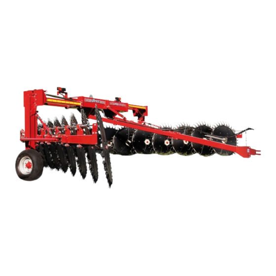
Maximum finished windrow width 72" Rake wheel hubs Tapered bearing Tires 10.0/75-15,3 Minimum power required 80 HP - 60 KW Weight 3000 kg - 6610 lbs All data are indicative. Sitrex reserves the right to change them without advance notice. - Page 8 LOCATION OF LABELS AND DEVICES FOR SAFETY, FOR CONTROLS AND FOR IDENTIFICATION OF THE MACHINE AND THE MANUFACTURER.
- Page 9 LOCATION OF LABELS AND DEVICES FOR SAFETY, FOR CONTROLS AND FOR IDENTIFICATION OF THE MACHINE AND THE MANUFACTURER IDENTIFICATION PLATE LARGE SITREX LOGO "PRO 17" STICKER SMALL SITREX LOGO RH EXTENSION MEASUREMENT STICKER See pg.5 (point 10) LH EXTENSION MEASUREMENT STICKER See pg.5 (point 10)
-
Page 10: Delivery And Assembly
4) DELIVERY AND ASSEMBLY CHECKING THE MACHINE ON DELIVERY All parts are carefully checked before dispatch or delivery. On receiving the machine, ensure that it not been damaged during transport. If damage has occurred, contact the dealer concerned. Note well: the packing consists of wood, plastic film, cardboard and steel supports, and must be disposed of according to the laws in force in your area. - Page 11 Each machine arrives packed in two crates and one pallet...
- Page 12 Assembly instructions Examples of general measurements for identifying the assembly accessories based on type. To make it easier to identify the assembly accessories (bolts, nuts, washers, pins, etc.) according to the general dimensions and the type, we provide a diagram that shows you the accessory parts to which the measurements refer in the various steps of the assembly.
- Page 13 Assembly instructions Examples of general measurements for identifying the assembly accessories based on type. When tightening the bolts refer to the tightening torque table (the class of the material is generally stamped on the head of the bolts).
-
Page 14: Assembly Sequence
ASSEMBLY SEQUENCE POINT 1 POINT 2... - Page 15 Assembly Sequence Note: In the description of the assembly sequence the terms “right” and “left” will be used in reference to the sides of the machine. “Right” and “left” are conventionally assigned looking at the machine from the rear (see box “C”). As already mentioned in the recommendations in the assembly instructions chapter, much care and caution as well as the proper tools and a suitable area must be used during these operations.
- Page 16 POINT 3...
- Page 17 Point 3 (DANGER) Keep the parts already assembled adequately raised using the lift A or B. Attach supports 1 to supports 2-3 (RH and LH) using bolts 4 and nuts 5. Support 1 attached to support 2 must appear as shown in box “C”, and support 1 attached to support 3 must appear as shown in box “D”.
- Page 18 POINT 4...
- Page 19 Point 4 (DANGER) Keep the parts already assembled adequately balanced using the lift A or B. To improve the stability of the parts assembled, chock the wheels with chocks “C”. Note: from this point on the parts to be added no longer weigh directly on the lift, which now serves mainly to keep assembly 1 balanced, as it rests on the ground with the wheels.
- Page 20 POINT 5...
- Page 21 Point 5 (DANGER) Keep the parts already assembled adequately balanced using the lift A or B. Attach the front drawbar 3 between drawbars 1-2 (RH and LH) at the measure of about 50 mm – 2” using bolts 4 and nuts 5 (see box “C”). This measure allows normal operation but it can be adapted for the various needs of the user depending on the type of tractor used, the land to be worked, etc.
- Page 22 POINT 6...
- Page 23 Point 6 (DANGER) The assembly done so far gives the machine good stability; however, proceed with caution. Attach the ratchet link 3 to the bracket 1 on the crosspieces assembly and to bracket 2 on the drawbar crosspiece using pins 4 and split pins 5. Attach the safety arm 7 to the free ends of pins 4 and fasten with the washers 8 and spring pins 9.
- Page 24 POINT 7...
- Page 25 Point 7 (ATTENTION) The assembly done so far (see box “A”) gives the machine full stability, therefore the lifts can be removed. Do not remove chocks “B” from the wheels. Continue assembly using maximum caution. Attach the sections 3-4 (RH and LH) to the supports 1-2 using the counterplates 5, bolts 6 and nuts 7.
- Page 26 POINT 8...
- Page 27 Point 8 (ATTENTION) Continue assembly using maximum caution. Note: in some cases, for packing necessities or to facilitate assembly, screws, bolts, washers, nuts and accessories have been preassembled by the manufacturer, and therefore they must be removed in order to carry out the assembly. The parts not preassembled are found in the nuts &...
- Page 28 POINT 9...
- Page 29 Point 9 (ATTENTION) Continue assembly using maximum caution. Attach RH section 1 to RH section 2 using bolts 3 support 15 and nuts 4. Connect tube 6 on section 2 to tube 7 on section 1 by means of pin 5 (see box “A”) using bolts 8-9 and nuts 10.
- Page 30 POINT 10...
- Page 31 Point 10 (ATTENTION) Continue assembly using maximum caution. Insert pins 1 into opening 2 in the tubes on sections 3-4 (RH and LH). Attach brackets 5 to the ends of sections 3-4 using screws 6, washers 7 and nuts 8. Join pins 1 to brackets 5 using the washers 9 and screws 10.
- Page 32 POINT 11...
- Page 33 Point 11 (ATTENTION) Continue assembly using maximum caution. Attach the ratchet links 1 to sections 2-3 (RH and LH) and to brackets 4-5 (RH and LH) using the pins 6 and split pins 7. If the ratchet links do not couple perfectly to brackets 2-3-4-5, loosen clamps B-C and move lever A to adjust them to the right length.
- Page 34 POINT 12...
- Page 35 Point 12 (ATTENTION) Continue assembly using maximum caution. Attach supports 1-2 to brackets (RH and LH side) using bolts 3, nuts 4, bolts 5, spacers 6 and nuts 7. Attach bracket 10 to sections 8-9 (RH-LH) and fasten at position B using the counterplate 11, bolts 12 and nuts 13. At this time do not tighten fully nuts 13.
- Page 36 POINT 13...
- Page 37 Point 13 (ATTENTION) Prior to the assembly of arms, rake wheels and accessories, we recommend to assemble the hydraulic system in order to have more room to manoeuvre. Although the assembly of the hydraulic system requires attention, difficulties will be minimal because the most complex parts have been pre-assembled by the manufacturer.
- Page 38 POINT 14...
- Page 39 Point 14 (ATTENTION) The hoses 1-2 to be assembled in this step may be found partially pre-assembled in the area “C” of the crosspiece assembly. Attach nipple 5 and washer 4 at point A5 on the valve of cylinder 3. Attach fitting 6 to the nipple 5.
- Page 40 POINT 15...
- Page 41 Point 15 (ATTENTION) Attach the female end of hoses 1 to the couplings B-C in area A of the frame. Attach two hoses 1 to couplings B and two to couplings C. Lay hoses 1 all along the drawbar. Attach quick couplings 2 to the ends of hoses 1. Note: to avoid problems with leaks, apply Loctite between the hoses 1 and quick couplings 2.
- Page 42 POINT 16...
- Page 43 Point 16 (ATTENTION) Attach protection 1 on pin “A” (the longer of the two) of RH arm 2. Attach pin “A” of RH arm 2 on the respective opening “B” of RH section 3. Fasten RH arm 2 to the opening “B”...
- Page 44 POINT 17...
- Page 45 Point 17 (ATTENTION) You have received seventeen spring pin assemblies 1 that have been pre-assembled by the manufacturer (see box “A”). Every spring assembly consists of a set of parts such as the U-bolt “B” and chain “C”, which make it possible to hook onto brackets “D” on the rake wheel pipes on sections 2-3 (RH and LH), and U-bolt “E”, which makes it possible to hook onto holes “F”...
- Page 46 POINT 18...
- Page 47 Point 18 (ATTENTION) Attach protection 1 to the pin of RH arm 2. Connect the central washer of RH rake wheel 3 to the pin of RH arm 2 and fasten it with washer 4 and nut 5. There are nine RH rake wheels 3.
- Page 48 5) ADJUSTMENT, PREPARATION AND USE a) attaching the machine to the tractor...
- Page 49 5) ADJUSTMENT, PREPARATION AND USE a) attaching the machine to the tractor The attachment of the machine to the tractor is simple but dangerous. Carry out the operation being extremely careful and strictly following these instructions. Make sure that there are no persons or objects within the operating range of the machine and tractor.
- Page 50 b) PREPARING THE MACHINE FOR FUNCTIONAL TESTS.
- Page 51 b) PREPARING THE MACHINE FOR FUNCTIONAL TESTS. As mentioned earlier, the machine must be lubricated before proceeding with the functional tests (see pages 62-63). Check the parts lubricated by the manufacturer as well. Before starting the machine for the functional tests, check to make sure that everything has been done correctly;...
- Page 52 b) FUNCTIONAL TESTS.
- Page 53 b) FUNCTIONAL TESTS. NB: In this case, as the machine has just been assembled, the description given here is intended for the functional tests before transporting it and subsequently before working, but this procedure should be carried out every time you have to attach the machine to the tractor.
- Page 54 c) TRANSPORT BY ROAD See pages 56- 57-58-59-60-61 Whenever you transport the machine, check that the information shown on the drawing above is followed. After the machine has been attached to the tractor as previously described and before transporting it to or from fields or any other workplace, the following instructions should be heeded: Before setting off with the machine attached to the tractor, check the local road transport regulations.
-
Page 55: Use In The Field
d) USE IN THE FIELD GENERAL INSTRUCTIONS FOR FIELD Before starting work, familiarise yourself with the following general instructions: Before using the machine ensure that all safety precautions are taken. Check that all safety protection and guards are in place and working. Inspect the work site in order to familiarise yourself with the terrain. - Page 56 d) USE IN THE FIELD...
- Page 57 d) USE IN THE FIELD The first thing to do when you are going to work is to open the machine frame. To do this, with the machine running, or at least on a surface that allows the transport wheels to slide sideways, move lever 1 connected to hoses 2 (see box A), which control the cylinders 3 (see box B) that open the sliding crosspieces to a max.
- Page 58 d) USE IN THE FIELD...
- Page 59 d) USE IN THE FIELD If rake wheels 4-5 dig into the soil, the contact with the ground must be lightened. To do this, the chain of spring assemblies 13 must be moved from the 4th link (see box H) as set by the manufacturer, or from whatever link was being used, to the 2nd link (see box L).
- Page 60 d) USE IN THE FIELD...
- Page 61 d) USE IN THE FIELD Note: if you begin transport without putting the block 19 in the lower position the rake wheels 6-7 will be float slightly during transport, but if you travel at a moderate speed this will not create problems. For long distances over uneven ground, instead, the block 19 must be returned to the lowered position.
-
Page 62: Maintenance Points
MAINTENANCE POINTS... -
Page 63: Operation
MAINTENANCE POINTS ITEM Q.ty DESCRIPTION OPERATION Every NOTES hours 34 RAKE WHEEL ARM LUBRICATE 15 BUSHING LUBRICATE SECTION JOINT LUBRICATE TANDEM PIN AND HUB LUBRICATE DRAWBAR PIN LUBRICATE RATCHET LINK LUBRICATE SUPPORT PIN CLEAN/ SEE NOTE A LUBRICATE SLIDING CROSSPIECE CLEAN/ SEE NOTE B LUBRICATE... - Page 64 C = Each time an adjustment is made it is a good practice to clean and brush with grease to facilitate sliding. Do this also after a rest period, at the end of the season when the machine is put away and when it is used again the next year, as the grease loses its effectiveness due to atmospheric agents.
- Page 65 GENERAL INSTRUCTIONS FOR REPAIR WORK Any repair work must be carried out with the machine at rest and disconnected from the tractor. Do not carry out welding without authorisation and instructions from the manufacturers. Disconnect the machine from the tractor before any welding work in order not to damage the battery.
- Page 66 LAYNING UP FOR EXTENDED PERIODS At the end of the season, or when an extended period of inactivity is envisaged, it is advisable to: Clean the machine following instructions an allow it to dry. Check it carefully and replace any damaged or worn parts. Thoroughly tighten all screws and bolts.
-
Page 67: Noise And Vibration
NOISE AND VIBRATION Noise affecting the tractor driver (from the machine only) is less than 80dB. Vibration from the machine affecting the upper body and limbs of the driver is insignificant and is lower than the values given in Point 3.6.3 of Enclosure 1 of the Machine Directives (89/392/EEC, 91/386/EEC) THE FOLLOWING SHOULD BE NOTED IF THE MACHINE IS SCRAPPED... - Page 68 Zona Industriale-Viale Grecia, 8 06018 TRESTINA-(Perugia)-ITALY Tel. +39.075.8540021-Telefax +39.075.8540523 e-mail: sitrex@sitrex.it www.sitrex.com...
Need help?
Do you have a question about the PRO Series and is the answer not in the manual?
Questions and answers