
Subscribe to Our Youtube Channel
Related Manuals for sitrex RT/5800-H


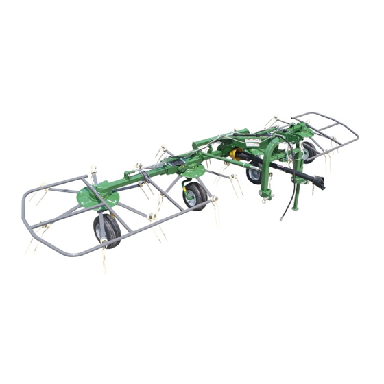
Summary of Contents for sitrex RT/5800-H
- Page 1 ASSEMBLY, USE AND MAINTENANCE SPARE PARTS LIST RT/5800-H POINT HITCH ROTARY TEDDER 10/06...
-
Page 2: Warranty
WARRANTY On delivery, check that the machine has not been damaged during transport and that all the attachments are present. Claims must be made in writing to the agent within 8 days of receipt. The manufacturer warrants new machinery at the time of delivery to the original purchaser to be free from defects in material and workmanship if properly set up and operated in accordance with this Operator’s Manual. -
Page 3: Warning Signs
1) GUIDE TO THE SIGNS AND SYMBOLS USED ON THE MACHINE IMPORTANT These signs and symbols give information to the operator on how to make the best use of the machine so as to prolong life, avoid damage, optimise work and, above all, to avoid injury to the operator and anyone within range of the machine. - Page 4 6) Indicates that there is a risk of crushing your hands. Keep your distance. 7) Indicates danger caused by accidental fall of suspended arms. Keep safe distance. 8) Indicates that it is dangerous to touch the cardan (P.T.O.) shaft. For all the other information regarding the cardan shaft, see the use and maintenance booklet specifically for the cardan shaft which, together with this manual, makes up the documentation on safety, use and maintenance of the machine.
-
Page 8: Product Identification
11'' (3,35 m) Weight 1320 lbs (600 kg) Tire 16x6.50-8 PTO Tractor requirement 25 hp (18 kw) PTO slip clutch Standard Operating speed 10 mph (16 Km/h) All data are indicative. Sitrex reserves the right to change them without advance notice. -
Page 9: Delivery And Assembly
FORKLIFT LIFTING POINTS MACHINE WEIGHT PACKING KG/LBS WEIGHT KG/LBS RT/5800-H 665/1465 600/1320 NOTE: 1) The packing consists mainly of wood, which should be disposed of according to the laws in force in the country where the machine is used. The plastic film should also be disposed of according to the laws in force in the country where the machine is used. - Page 10 ASSEMBLY INSTRUCTIONS Assembly is highly dangerous and must be carried out in strict accordance with the following instructions. We recommend that qualified personnel perform assembly. We also recommend that assembly be carried out on a flat, solid surface, in an open area with no people (particularly children) nearby who could be severely injured if they were to touch or move any parts of the machine.
- Page 13 STEP “A” Attach the guard 1 to the central gear box 2 using the nuts 3. In this step, you will use: Item 3 : 2 nuts M8 (0.31“) STEP “B” NB. The plates “A” are assembled to the chassis of the machine by the manufacturer.
- Page 14 STEP “C” Mount the pin 1 onto its seat on the frame 2. Fit the washer 3, the shim 4 and the bush 5 onto the pin and secure the whole assembly into place with the spring pin 6. Rise the lever “A”...
- Page 15 STEP “D” Return lever “A” to its original horizontal position. Mount the supports 2-3 (RH-LH) on their seats in the 3rd point hitch 1 using the pins 4 and the spring pins 5. Mount the pins 6 onto their seats on the supports 2-3 using the spring washers 7 and the nuts 8.
- Page 16 STEP “G” Mount the shock absorbers 1 on the seats provided for them on the 3rd point hitch 2 and the chassis of the machine 3 and fasten them with the pins 4 and the spring pins 5. Apply the eye bolts to the seats provided on the chassis of the machine and 6 and fasten them with the nuts 7.
- Page 17 STEP “H” (cont.d from previous page) Attach the tine bars 1 (RH) and 2 (LH) to their respective rotors 3-5 (RH) and 4-6 (LH) with screws 7, spring washers 8, washers 8, screws 10 and nuts 11. In this step, you will use: Item 7 : 24 screws M12x30 (0.47”x1.18”) Item 8 : 24 spring washers ø13 (ø0.51”) Item 9 : 24 washers ø13 (ø0.51”)
- Page 18 STEP “M” Attach the guards 3 (RH and LH side) and plates 4-5 using washers 6 and screws 7. Attach grease nipples 1-2 in the proper holes (RH and LH side). In this step, you will use: Item 1 : 2 grease nipples M10 Item 2 : 4 grease nipples M6 Item 6 : 8 flat washers ø8.5 (ø0.33”) Item 7 : 8 screws M8x16 (0.31”x0.63”)
- Page 19 STEP “A” Attach the cylinders 7-8 (RH-LH) using pins 9 and spring pins 10. In this step, you will use: Item 9 : 2 pins ø20x70 (0.79”x2.76”) Item 10 : 4 spring pins ø6x35 (0.24”x1.38”) STEP “B” Continue to secure cylinders 7-8 (RH-LH) using pins 1 and spring pins 2.
- Page 20 STEP “E”-“F” Join hoses 2 to connector 1. Attach nipple 3 to connector 1. Attach hose 4 to nipple 3. Secure hose 4 with collars 5 and screws 6. In this step, you will use: Item 1 : 1 “T” connector 1/4” Item 2 : 2 hoses (step C-D) Item 3 : 1 nipple 1/4”...
- Page 21 STEP “H” Rest the hose 5 and the rope 6 on the support 1. Apply the copper washer 7 and the rapid coupling 8 to the hose. In this step, you will use: Item 5 : 1 hose (see item 4 on step “E”) Item 7 : 1 copper washer ½”...
- Page 22 5) ADJUSTMENT,PREPARATION AND USE...
- Page 23 5) ADJUSTMENT, PREPARATION AND USE INTRODUCTION Connection to the tractor is highly dangerous. Take great care and carry out the entire operation in strict compliance with the following instructions. Nobody should go near the area between the tractor and the machine. Check that all warning and danger signs are in place and legible.
-
Page 25: Transport Instructions
TRANSPORT INSTRUCTIONS Before transporting, the side arms 1-2 (see page 24). must be raised. To do this move the distributor lever 3, sending fluid through hoses 4-5 to cylinders 6-7, which will close, lifting the side arms 1-2. Before proceeding with transport, make sure that catch 9 is firmly hooked on pin 10 (RH and LH side) in order to guarantee safety while the machine is being transported. -
Page 26: Use In The Field
USE IN THE FIELD... - Page 27 PREPARATIONS FOR USE To lower the side arms 1-2 (see page 26) of the RT/5800 hydraulic fold, move the distributor lever 3 so as to send fluid through hoses 4-5 to cylinders 6-7, which will close completely, pulling rope 8 at the same time as when moving distributor lever 3, thus making it possible to release catch 9 from pin 10 (RH and LH side), and then moving distributor lever 3 so as to lower side arms 1-2 down to the ground.
-
Page 28: Temporary Parking
TEMPORARY PARKING 1) Choose a flat, hard open space away from frequented areas if possible. 2) Switch off the engine, leaving the tractor in gear. 3) Apply the parking brake and remove the ignition key. 4) Put the parking stand in the parking position. 5) Turn the angle adjustment crank so that the weight of the machine is on the parking stand, thus avoiding the risk of having the machine tip over backwards. - Page 29 6) MAINTENANCE DIRECTIONS All cleaning, lubrication and maintenance operation must be carried out with the machine disconnected from the tractor. In an emergency with the machine still connected to the tractor, switch off the engine, apply the parking brake, disengage the power takeoff and remove the ignition key from the instrument panel.
-
Page 30: Maintenance Points
6) MAINTENANCE POINTS... - Page 31 6) MAINTENANCE POINTS ITEM Q.ty DESCRIPTION OPERATION EVERY NOTES HOURS GEARBOX LUBRICATE SEE NOTE A CENTRAL ROTORS LUBRICATE LATERAL ROTORS LUBRICATE SWIVEL HINGE PINS LUBRICATE UNIVERSAL JOINTS LUBRICATE KEYED COUPLING LUBRICATE FORK POINT HITCH LUBRICATE WHEEL SUPPORTS LUBRICATE ARM LINKAGE PINS CLEAN WITH NOTE C...
- Page 33 GENERAL INSTRUCTIONS FOR REPAIR WORK Any repair work must be carried out with the machine at rest and disconnected from the tractor. Do not carry out welding without authorisation and instructions from the manufacturers. Disconnect the machine from the tractor before any welding work in order not to damage the battery.
-
Page 34: Noise And Vibration
NOISE AND VIBRATION Noise affecting the tractor driver (from the machine only) is less than 80dB. Vibration from the machine affecting the upper body and limbs of the driver is insignificant and is lower than the values given in Point 3.6.3 of Enclosure 1 of the Machine Directives (89/392/EEC, 91/386/EEC) THE FOLLOWING SHOULD BE NOTED IF THE MACHINE IS SCRAPPED... -
Page 35: Spare Parts List
SPARE PARTS LIST FOR CORRECT SPARE PARTS ORDER IT IS NECESSARY TO SPECIFICY: TABLE NOMBER, ITEM, PART NO, DESCRIPTION AND QUANTITY OF PARTS REQUIRED. ITEMS DESCRIBED AS RH AND LH ARE MEANT FACING REAR OF MACHINE. - Page 37 RT/5800 3rd POINT HITCH - TABLE PART NO 920.227 ITEM Q.ty PART NO DESCRIPTION NOTE 220.990 3rd POINT HITCH 220.992 DRAWBAR 230.016 SUPPORT 220.053 210.560 600.538 SPRING PIN (ø6x35) 210.530 SHIM 220.237 BUSH 220.055 BUSH 600.584 SPRING PIN (ø10x50) 600.830 HANDLE 220.252 LEVER...
- Page 39 RT/5800-H 3rd POINT HITCH - TABLE PART NO 920.228 ITEM Q.ty PART NO DESCRIPTION NOTE 220.838 RH LATERAL GUARD 220.839 LH LATERAL GUARD 600.854 PLUG 600.634 SPRING WASHER (ø13-ZN) 600.770 SCREW (M12x20 5739-ZN) 600.441 SCREW (M12x25 5739-ZN) 210.009 ROPE 220.822 RH CYLINDER 220.823...
- Page 41 RT/5800-H 3rd POINT HITCH - TABLE PART NO 920.229 ITEM Q.ty PART NO DESCRIPTION NOTE 220.829 CYLINDER BARREL, RH 220.830 CYLINDER BARREL, LH 220.831 200.947 SPRING 210.288 CYLINDER HEAD 210.289 PISTON 610.025 GASKET 610.027 GASKET 610.026 GASKET 610.028 GASKET 610.029 GASKET 600.895...
- Page 43 RT/5800-H 3RD POINT HITCH - TABLE PART NO 920.230/a ITEM Q.ty PART NO DESCRIPTION NOTE 200.395 GEARBOX CAP 200.396 SHAFT 230.225 GEARBOX 220.791 RH CENTER AXLE 230.004 LH CENTER AXLE 220.994 REINFORCEMENT 220.652 RH FORK SUPPORT 220.653 LH FORK SUPPORT 220.788...
- Page 45 RT/5800-H -TABLE PART NO 920.219 ITEM Q.ty PART NO DESCRIPTION NOTE 220.793 RH LATERAL AXLE 220.794 LH LATERAL AXLE 220.651 FORK 220.789 LATERAL SHAFT 220.810 GUARD 220.811 PLATE 220.812 PLATE 200.850 600.808 BUSH (ø30/34x20) 600.609 BEARING (6206 2RS) 600.611 SNAP RING (E30-7435) 600.809...
- Page 47 RT/5800-H -TABLE PART NO 920.220 ITEM Q.ty PART NO DESCRIPTION NOTE 220.637 GEAR BOX 200.407 200.420 PINION 220.833 CROWN 220.834 TINE DISC 220.836 600.609 BEARING (6206 2RS) 600.559 FLAT KEY (B8x7x30-6604) 600.541 SPRING PIN (ø10x55-6873) 600.562 SPRING PIN (ø6x55-6873) 600.608 BEARING (6207 2RS) 600.049...
- Page 49 RT/5800 3rd POINT HITCH -TABLE PART NO 920.231 ITEM Q.ty PART NO DESCRIPTION NOTE 230.205 RH SUPPORT 230.206 LH SUPPORT 230.009 RH HUB 230.010 LH HUB 220.821 SPACER 200.419 SHIM (ø35,2/51,8x1) *Q.ty as required 200.274 SHIM (ø35,2/48x0,5) *Q.ty as required 200.490 SHIM (ø35,2/51,8x0,3) *Q.ty as required 600.568 GASKET (OR 47,63x3,53)
- Page 52 Zona Industriale-Viale Grecia, 8 06018 TRESTINA-(Perugia)-ITALY Tel. +39.075.8540021-Telefax +39.075.8540523 e-mail: sitrex@sitrex.it www.sitrex.com...
Need help?
Do you have a question about the RT/5800-H and is the answer not in the manual?
Questions and answers