
Subscribe to Our Youtube Channel
Related Manuals for sitrex SR 420/11 H


Summary of Contents for sitrex SR 420/11 H
- Page 1 USE AND MAINTENANCE SPARE PARTS LIST SR 420/11 H ROTARY RAKES HYDRAULIC LIFT Pull type...
- Page 2 Warranty On delivery, check that the machine has not been damaged during transport and that all the attachments are present. Claims must be made in writing to the agent within 8 days of receipt. The manufacturer warrants new machinery at the time of delivery to the original purchaser to be free from defects in material and workmanship if properly set up and operated in accordance with this Operator’s Manual.
- Page 3 GUIDE TO THE SIGNS AND SYMBOLS USED THIS MANUAL AND THEI LOCATION ON THE MACHINE IMPORTANT These signs and symbols give information to the operator on how to make the best use of the machine so as to prolong life, avoid damage, optimise work and, above all, to avoid injury to the operator and anyone within range of the machine.
-
Page 4: Oil Level
6) Indicates that there is a risk of crushing your hands. Keep your distance. 7) Indicates danger caused by accidental fall of suspended arms. Keep safe distance. 8) Indicates that it is dangerous to touch the cardan (P.T.O.) shaft. For all the other information regarding the cardan shaft, see the use and maintenance booklet specifically for the cardan shaft which, together with this manual, makes up the documentation on safety, use and maintenance of the machine. - Page 5 Prevention Instructions Read all the directions carefully before using the machine. When in doubt, seek advice from the manufacturers. The manufacturing company declines all responsibility for non-compliance with the following safety and accident-prevention instructions. 1- Pay attention to the danger signs and symbols in this manual and on the machine. 2- Do not touch moving parts.
- Page 6 23- Under no circumstances should anybody go between the tractor and the machine (Fig. 1) when the engine is running and the Cardan shaft is engaged, especially without first having applied the parking brake and placed chocks against the wheels. 24- Before connecting or disconnecting the machine to or from the 3-point linkage, put the lifting unit lever into the locked position.
- Page 7 42- Use the quantities of grease and oil advised. 43- Spare parts must meet the requirements as defined by the manufacturer. Use only original spare parts. 44- Safety decals must always be clearly visible. They must be kept clean and replaced if they become too illegible (they can be ordered from the agent if necessary).
-
Page 8: Product Identification
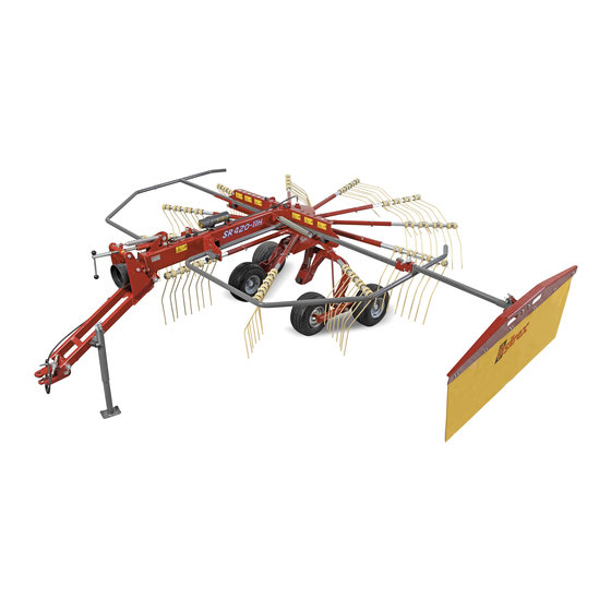
PRODUCT IDENTIFICATION MAIN PARTS 1) BRACKET 2) DRAWBAR 3) PARKING STAND 4) HYDRAULIC KIT 5) CRANK 6) RATCHET 7) FRAME 8) R.H. GUARD 9) TINE ARM 10) TINE 11) GEARBOX 12) AXLE 13) CYLINDER 14) TYRE ASSY 15) SWATHING DEFLECTOR 16) TELESCOPING TUBE 17) L.H. - Page 9 LOCATION OF SIGNS AND SYMBOLS ON THE MACHINE 1) SEE DRAWING 1 P.4 2) SEE DRAWING 2 P.4 3) SEE DRAWING 3 P.4 4) SEE DRAWING 4 P.5 5) SEE DRAWING 5 P.5 6) SEE DRAWING 6 P.5 7) SEE DRAWING 7 P.5 8) SEE DRAWING 8 P.5 9) SEE DRAWING 9 P.6 10) SEE DRAWING 10 P.6...
-
Page 10: Delivery And Assembly
CHAPTER 4 DELIVERY AND ASSEMBLY Checking the machine on delivery All parts are carefully checked before dispacth or delivery. On receiving the machine, ensure that it has not been damaged during transport. If damage has occurred, contact the dealer concerned. Details of packing are given below. - Page 11 Assembly is highly dangerous and must be carried out in strict accordance with the following instructions. We recommend that assembly be performed by qualified personnel. We also recommend that assembly be carried out in a flat, open area with no people (particularly children) nearby who could be severely injured if they were to touch or move any parts of the machine.
- Page 12 Rest the main frame (2) on stands and then insert the wear bushings (5). Insert pin (3) into hole (A) and fasten with the spring pin (42). Position the drawbar (1) so that pin (6) can be inserted, and fasten pin (6) with the spring pin (7). Attach grease nipples (17) to the axle (2).
-
Page 14: Hydraulic System Assembly
HYDRAULIC SYSTEM ASSEMBLY Remove the guard on the central screw of the housing (1), then screw on the cylinder (6), without touching the ring (2) or the lower toothed washer (4). When the cylinder is tight, bend one of the tabs of the upper toothed washer (5) on the milled part of the cylinder so as to fasten it. - Page 15 Mount the safety hook (2) by inserting it into hole (A), and then place the spring (4) and washer (5) over the pin, fastening in place with pin (6). Insert safety pin (7) in hole (B). ATTENTION: Mount the high rubber pad (7) to the right outside hole with nuts (6), taking also the plate (8);...
- Page 16 Mount safety hook (1) on to the pin (A) welded on to the frame, mount on safety hook the screw (2) and nut (3). Mount spring (4) to help suspension between the pin and the plate welded on the drawbar (see following diagram). Adjust screws (M10 x 60 fully threaded) so that the safety hook turns partially and is positioned vertically when the protection frame is horizontal.
- Page 17 In order to mount swathing deflector (29) insert the slanting metal tabs (30) into the external slots and the straight tabs into the central slots, and then rest the swathing deflector on the inside of side frame (27) and place plate (28) on the outside; use screws (32) and nuts (33) to fasten everything into place.
- Page 18 Mount the grease nipple (1) on all pin. Before assembling the rake arms, raise the protection frames and use hook 23 to hold them up. If the machine has to be set up for work, mount detachable arms 44 on to the fixed arms 45 and fasten them with pin 43; the two holes on the detachable arms are to adjust swath width.
-
Page 19: Connection To The Tractor
CHAPTER 5 ADJUSTMENT, PREPARATION AND USE INTRODUCTION Connection to the tractor is higly dangerous. Take great care and carry out the entire operation in strict compliance with the following instruction. Nobody should go near the area between the tractor and the machine. Check that all warning and danger signs are in place and legible. - Page 20 CONNECTING THE CARDAN SHAFT More detailed information may be found in the cardan shaft manual which, together with this manual, is an essential part of the accident-prevention documentation. It is your responsibility to read and comply with this documentation. If information given in this manual should conflict with that given in the cardan shaft manual, you should follow the instructions given by the cardan shaft manufacturer.
- Page 21 DISASSEMBLY OF THE TRACTOR In order to park the rake, make sure that the ground beneath it is flat and is able to bear the weight of the machine. When the rake is raised and lowered, no-one should be standing between the tractor and the machine or near the machine.
- Page 22 When the working height is being adjusted, set the screws (6) and relative nuts (8) so that the machine as seen in Fig. 19 is parallel to the ground. After having adjusted the work height of the tine, use nuts 5 under clamp 10 to set the distance of the plate from the ground.
- Page 23 TRANSPORT If the machine is used on the road, make sure it complies with traffic regulations in your country; use regulation lights and comply with the safety regulations. Preparation for transport The machine may be transported for short distances after having raised it with the hydraulic system.
- Page 24 MAINTENANCE DIRECTIONS All cleaning, lubrication and maintenance operations must be carried out with the machine disconnected from the tractor. In an emergency with the machine still connected to the tractor, switch off the engine, apply the parking brake, disengage the power takeoff and remove the ignition key from the instrument panel.
- Page 25 GENERAL INSTRUCTIONS FOR REPAIR WORK Any repair work must be carried out with the machine at rest and disconnected from the tractor. Do not carry out welding without authorization and instructions from the manufacturers. Disconnect the machine from the tractor before any welding work in order not to damage the battery.
-
Page 26: Maintenance Points
MAINTENANCE POINTS Number Q.ty Description Operation Every hours Product to be Notes used Equalizer Greasing Grease Gearbox Greasing Grease Gearbox Oil level Oil SAE90EP Screw Greasing Grease Power takeoff Cleaning Additives shaft Greasing Grease Bearing Greasing Grease Sliding Cleaning Additives Greasing Grease Tyres... - Page 27 CARDAN SHAFT MAINTENANCE More detailed information may be found in the Cardan shaft manual, which, together with this manual, forms an essential part of the accident-prevention documentation. It is your responsibility to read and comply with this documentation. If information given in this manual conflicts with that given in the Cardan shaft manual, you should follow the instructions given by the Cardan shaft manufacturer.
-
Page 28: Noise And Vibration
NOISE AND VIBRATION Noise affecting the tractor driver (from the machine only) is less than 70dB. Vibration from the machine affetcing the upper body and limbs of the driver is insignificant and is lower than the values given in Point 3.6.3 of Enclosure 1 of the Machine Directives (89/392/EEC, 91/386/EEC) THE FOLLOWING SHOULD BE NOTED IF THE MACHINE IS SCRAPPED The machine consists mainly of ferrous material which must be disposed of according to the... -
Page 29: Spare Parts List
SPARE PARTS LIST... - Page 31 TABLE NO. 920.117 420/11 Pull type ITEM Q.ty PART/NO DESCRIPTION NOTE 210.677 BRACKET 210.719 RH EQUALIZER 210.720 LH EQUALIZER 600.737 SCREW 600.611 SNAP RING 600.075 210.514 DRAWBAR 600.292 SCREW optyonal 600.080 optyonal 220.197 PARKING STAND 200.222 210.678 HINGE PIN 600.027 SPRING PIN 210.518/a 600.539...
- Page 33 TABLE NO. 920.118 420/11 Pull type ITEM Q.ty PART/NO DESCRIPTION NOTE 610.487 GEARBOX 210.727 CYLINDER 8.3.8.00336 WASHER 210.808 LATCH 210.741 600.108 SPRING PIN 210.723 210.682 TIEROD 210.742 210.762 LH SUPPORT 610.497 SCREW 620.206 210.725/a AXLE 600.032 610.167 SCREW 210.680/a ROD 210.681 SUPPORT 210.686/a PIN...
- Page 35 TABLE NO. 920.119 420/11 Pull type ITEM Q.ty PART/NO DESCRIPTION NOTE 210.513 FRAME 220.623 GUARD 220.622 RH GUARD SUPPORT 600.437 SCREw 600.029 610.186 610.521 RUBBER PAD 600.008 210.511 LIGHTING BRACKET 610.289 REFLECTOR 610.283 RUBBER PAD 210.615 PLATE 600.154 SCREW 210.557 SPRING 220.621 LH GUARD SUPPORT...
- Page 37 TABLE NO. 920.122/a 420/11 Pull type ITEM Q.ty PART/NO DESCRIPTION NOTE 210.513 FRAME 610.285 BEARING 610.167 SCREW 600.080 210.525 SHAFT 210.528 BUSH 610.417 SPRING PIN 610.419 SPRING PIN 610.487 GEARBOX 210.808 LATCH 210.494 PROFILE TUBE 600.842 210.767 TINE ARM 600.386 SCREW 600.077 210.495...
- Page 39 TABLE NO 920.109 ITEM PART NO Q.ty DESCRIPTION NOTE 220.732 GEAR BOX 220.721 GEAR 220.722 220.723 SCREW 620.177 SNAP RING 220.724 SHIM LATCH 620.178 620.179 WASHER 620.180 220.733 SHIM 620.127 BEARING 620.182 GREASE NIPPLE 620.163 GASKET 620.140 DUST COVER 220.726 SHIM 620.181 BEARING...
- Page 40 CARDAN SHAFT 620.867...
- Page 41 CARDAN SHAFT 620.867 ITEM DESCRIPTION Q.ty PART NO CHAIN 620.918 SPECIAL SCREW 620.919 GUARD 620.920 BEARING 620.921 YOKE 620.922 CROSS JOURNAL ASSEMBLY 620.923 CENTER JOINT 620.924 YOKE 620.925 SPRING PIN 620.926 CARDAN TUBE 630.579 HALF SAFETY GUARD 630.580 HALF SHAFT (WITH GUARD) 630.581 HALF SAFETY GUARD 630.582...
- Page 42 H&S MANUFACTURING CO. INC. 2608 S. Hume Ave. P.O. Box 768 - Telephone (715) 387-3414 FAX Number (715) 384-5463 MARSHFIELD, WI 54449...
Need help?
Do you have a question about the SR 420/11 H and is the answer not in the manual?
Questions and answers