Table of Contents
Advertisement
Quick Links
Use and Maintenance Manual – 002.108A of _27/09/2021
USE AND MAINTENANCE
MANUAL
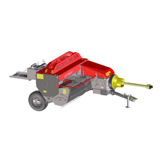
SQUARE BALER
M 60 MINI/S
M 60 MINI
M 60 SUPER
SITREX S.p.A. – Agricultural Machinery
Zona Industriale – Viale Grecia, 22 – 06018
Trestina (PG) – Italy
Original instructions.
Square Baler – M 60 Mini/S – M 60 Mini – M 60 Super
1
Advertisement
Table of Contents

Related Manuals for sitrex M 60 MINI/S


Summary of Contents for sitrex M 60 MINI/S
- Page 1 M 60 MINI/S M 60 MINI M 60 SUPER SITREX S.p.A. – Agricultural Machinery Zona Industriale – Viale Grecia, 22 – 06018 Trestina (PG) – Italy Original instructions. Square Baler – M 60 Mini/S – M 60 Mini – M 60 Super...
-
Page 2: Table Of Contents
.............................. 55 NOTTER ADJUSTMENT 7.4.1 K ..........................55 NOTTER BRAKE ADJUSTMENT 7.4.2 H ........................56 OLDER DISC PRESSURE ADJUSTMENT 7.4.3 H ........................57 OLDER DISC POSITION ADJUSTMENT Square Baler – M 60 Mini/S – M 60 Mini – M 60 Super... - Page 3 11.2 TWINE KNOTTER MALFUNCTIONS ......................... 92 12 END OF LIFE ............................. 95 13 WARRANTY ............................... 95 14 ORDERING SPARE PARTS ........................96 15 SPARE PARTS CATALOGUE ........................96 Square Baler – M 60 Mini/S – M 60 Mini – M 60 Super...
-
Page 4: Information Regarding The Manual
The manufacturer reserves the right to make improvements or modifications when the improvements or modifications become practical and possible, without incurring any obligation to make modifications or additions to machines and equipment sold previously. Square Baler – M 60 Mini/S – M 60 Mini – M 60 Super... -
Page 5: Marking And Identification
Each machine is equipped with a CE nameplate and a declaration of conformity in compliance with Directive 2006/42/EC and subsequent amendments. Location of the nameplate Fig. 2.1 2.1 Machine nameplate example Fig. 2.2 Square Baler – M 60 Mini/S – M 60 Mini – M 60 Super... -
Page 6: Ce Certificate Example
Use and Maintenance Manual – 002.108A of _27/09/2021 2.2 CE certificate example Square Baler – M 60 Mini/S – M 60 Mini – M 60 Super... -
Page 7: Machine Specifications
Pickup wheel PTO shaft Hydraulic pickup lift Third wheel bracket Hydraulic drawbar adjustment Wide-angle PTO shaft Long chute and trailer hitch Lights kit Pickup support roller Square Baler – M 60 Mini/S – M 60 Mini – M 60 Super... -
Page 8: Machine Parts Identification
4. PTO shaft 5. Flywheel 6. Reduction gear 7. Pickup 8. Wheel 9. Bale chamber 10. Bale chute 11. Forks 12. Plunger 13. Knotter 14. Twine box Square Baler – M 60 Mini/S – M 60 Mini – M 60 Super... -
Page 9: Safety
Make sure there are no persons near the machine during operations involving tipping and moving hydraulic parts. The parts driven by external forces have sharp, pointed ends. Square Baler – M 60 Mini/S – M 60 Mini – M 60 Super... - Page 10 The noise level in the driver's seat is: L = 79.5 dBA. Ear protectors are recommended when using the tractor without a soundproof cab (if the noise level exceeds 85 dBA) Square Baler – M 60 Mini/S – M 60 Mini – M 60 Super...
- Page 11 CAUTION “CAUTION” warns that if the operations described are not carried out correctly, they may cause damage to the machine and/or injury to person. Square Baler – M 60 Mini/S – M 60 Mini – M 60 Super...
-
Page 12: Location Of Safety Signs
Use and Maintenance Manual – 002.108A of _27/09/2021 3.2 Location of safety signs Fig. 3.1 Square Baler – M 60 Mini/S – M 60 Mini – M 60 Super... -
Page 13: Meaning Of The Pictographs
When transporting the machine, you must use the customary signals. The firm declines all liability if the aforesaid rules and instructions are not followed. Square Baler – M 60 Mini/S – M 60 Mini – M 60 Super... - Page 14 Keep a safe distance when closing the rear from the machine. chamber. The casings MUST be Maximum rotation closed before starting speed of the PTO the machine. shaft. Square Baler – M 60 Mini/S – M 60 Mini – M 60 Super...
- Page 15 Indicates the maximum vertical load on the towing eye. Keep away from the PTO and PTO shaft when the machine is operating. Warning Square Baler – M 60 Mini/S – M 60 Mini – M 60 Super...
- Page 16 Use and Maintenance Manual – 002.108A of _27/09/2021 Maintenance notice Greasing points Anchor points Oil level check Indicates the transport and working positions Square Baler – M 60 Mini/S – M 60 Mini – M 60 Super...
-
Page 17: Intended Use Of The Machine
Zone B, residual hazard during all the operations in which the PDF is active and/or while moving forward; Zone C, residual hazard during the baling operation (bale discharge), while moving in reverse, and during maneuvers. Square Baler – M 60 Mini/S – M 60 Mini – M 60 Super... -
Page 18: Shipping, Assembly And Handling
The parts that can be disassembled for shipping are (Fig. 4.2): Tongue (3), Wheels (1, 2), Upper protective guards (4), PTO shaft (5) Joint protective casing (6) Square Baler – M 60 Mini/S – M 60 Mini – M 60 Super... - Page 19 Some parts that are supplied with the machine can be disassembled; these are packed as shown in Fig. 4.3 Ref. 1 Shear bolts supplied Ref. 2 Joint protective casing; Ref. 3 PTO shaft; Ref. 4 Manuals. Square Baler – M 60 Mini/S – M 60 Mini – M 60 Super...
-
Page 20: Machine Assembly
It is necessary to have a lifting hoist of adequate capacity, and hooks must be attached to the machine as shown in Fig. 4.4. Square Baler – M 60 Mini/S – M 60 Mini – M 60 Super... - Page 21 Other parts that can be disassembled are: The upper guards and the PTO shaft protective shield. Figure 4.5 shows how they are to be assembled. Square Baler – M 60 Mini/S – M 60 Mini – M 60 Super...
- Page 22 Use and Maintenance Manual – 002.108A of _27/09/2021 Fig. 4.5 Square Baler – M 60 Mini/S – M 60 Mini – M 60 Super...
-
Page 23: Putting Into Operation And Use
While the machine is being used there are danger zones connected with the operations that are being carried out: keep objects and people away from these zones. There is danger of death, serious injury, or long-term risks. Fig. 5.1 Square Baler – M 60 Mini/S – M 60 Mini – M 60 Super... -
Page 24: Checks Before Putting Into Operation
Next, raise the machine parking stand, placing it in the position shown in Fig. 5.2. Square Baler – M 60 Mini/S – M 60 Mini – M 60 Super... - Page 25 Incorrect hitching to the tractor subjects the PTO shaft universal joints to abnormal loads and causes the baler to operate abnormally, with possible damage to its parts. Square Baler – M 60 Mini/S – M 60 Mini – M 60 Super...
-
Page 26: Transporting The Machine
4) Release the lever to lock the drawbar in the “drawbar open” position (or release the lever from the tractor by means of cable 5). 5) Make sure that the pin is inserted in one of the two positions. Square Baler – M 60 Mini/S – M 60 Mini – M 60 Super... - Page 27 Use and Maintenance Manual – 002.108A of _27/09/2021 Fig. 5.5 Square Baler – M 60 Mini/S – M 60 Mini – M 60 Super...
- Page 28 There is danger of death or serious injury. Fig. 5.7 Check that there is an overlap between the protective shields of at least as much as that shown in Fig. 5.7 Square Baler – M 60 Mini/S – M 60 Mini – M 60 Super...
-
Page 29: Loading The Twine
(the needle holder arm must be in the rest position with the needles retracted) 6 Remove the two pieces of twine that are still tied to the crossbar. Square Baler – M 60 Mini/S – M 60 Mini – M 60 Super... - Page 30 Use and Maintenance Manual – 002.108A of _27/09/2021 Fig. 5.8 Square Baler – M 60 Mini/S – M 60 Mini – M 60 Super...
- Page 31 Use and Maintenance Manual – 002.108A of _27/09/2021 Fig. 5.9 Square Baler – M 60 Mini/S – M 60 Mini – M 60 Super...
-
Page 32: Baling
After baling a few bales, check to see if they are well bound and have the required weight and length. For any adjustments, see section 7.5. Square Baler – M 60 Mini/S – M 60 Mini – M 60 Super... -
Page 33: Maneuvers At The End Of The Row
5) Release the lever to lock the drawbar in the “drawbar closed” position (or release the lever from the tractor by means of cable 5). See Fig. 5.11. Square Baler – M 60 Mini/S – M 60 Mini – M 60 Super... - Page 34 Use and Maintenance Manual – 002.108A of _27/09/2021 Fig. 5.11 Square Baler – M 60 Mini/S – M 60 Mini – M 60 Super...
-
Page 35: Parking The Baler
Remove the hitch pin, ensuring that the machine remains stationary by itself in the parking position. If the machine is to remain parked for a long time (end of season), see Chapter 9. Fig. 5.12 Square Baler – M 60 Mini/S – M 60 Mini – M 60 Super... -
Page 36: Maintenance
3.2. Table 6.1 lists the maintenance operations and indicates where and when to carry them out. Table 6.2 indicates the materials needed for maintenance operations. Square Baler – M 60 Mini/S – M 60 Mini – M 60 Super... -
Page 37: Maintenance Table
Use and Maintenance Manual – 002.108A of _27/09/2021 6.1 Maintenance Table Fig. 6.1 Square Baler – M 60 Mini/S – M 60 Mini – M 60 Super... - Page 38 Check that needle rollers rotate freely Check hydraulic hoses for fluid leaks Check safety decals Check wear of twine guides Check wear Check electrical system Table 6.1 Square Baler – M 60 Mini/S – M 60 Mini – M 60 Super...
-
Page 39: Table Of Maintenance Equipment
Knotter control shear bolt 1st fork shear bolt 2nd fork shear bolt To avoid altering the operation of these safety devices, restore them with components having equivalent mechanical specifications. Square Baler – M 60 Mini/S – M 60 Mini – M 60 Super... -
Page 40: Flywheel Clutch
PTO stopping stage; therefore do not approach the machine during this stage until the parts have fully stopped. Fig. 6.2 Square Baler – M 60 Mini/S – M 60 Mini – M 60 Super... -
Page 41: Flywheel Shear Bolt
To increase the life of the shear bolt, make sure that it is tight. When the bolt breaks, wait for the flywheel to stop before approaching the machine. Square Baler – M 60 Mini/S – M 60 Mini – M 60 Super... -
Page 42: Pickup Control Shaft Safety Device
It slips when the pickup offers too much resistance. It can be adjusted by means of the tensioner (ref. 8, Fig. 27); to adjust it, see sect. 7.2.3. Fig. 6.4 Square Baler – M 60 Mini/S – M 60 Mini – M 60 Super... -
Page 43: Knotter Control Shear Bolt
This means locking the lever A (Fig. 6.4) in the low position as shown in the figure: Fig. 6.5 Square Baler – M 60 Mini/S – M 60 Mini – M 60 Super... -
Page 44: St Fork Shear Bolt
Remove the cause of the break, time the fork (if necessary) and insert the new bolt. Fig. 6.6 Square Baler – M 60 Mini/S – M 60 Mini – M 60 Super... -
Page 45: Nd Fork Shear Bolt
Remove the cause of the break, time the fork and insert the new bolt. Fig. 6.7 Square Baler – M 60 Mini/S – M 60 Mini – M 60 Super... -
Page 46: Pickup Springs Replacement
Also remove the material in front of the pickup and near the bale chamber, so that the pickup springs and carriage are not in contact with the material. Square Baler – M 60 Mini/S – M 60 Mini – M 60 Super... -
Page 47: Adjustments
The tongue can have two possible working positions (ref. 1 and ref. 2, Fig. 7.2); in position 2, the machine increases the distance between the tractor and the hay swath, adapting to greater tractor widths. Square Baler – M 60 Mini/S – M 60 Mini – M 60 Super... -
Page 48: Drive Adjustment (Timing)
Under these conditions, the gear 1 (Fig. 7.3) is secured to its axle with the Allen screws. The multi-hole flange system makes it possible to lock the gear 1 (Fig. 7.3) in the required position with a minimum deviation. Square Baler – M 60 Mini/S – M 60 Mini – M 60 Super... - Page 49 Use and Maintenance Manual – 002.108A of _27/09/2021 Fig. 7.3 Fig. 7.4 Fig. 7.5 Square Baler – M 60 Mini/S – M 60 Mini – M 60 Super...
-
Page 50: Timing Of The Knotter/Needles With The Carriage (B)
4) Continue to rotate the bell gear 3 (Fig. 7.7) counterclockwise, moving it repeatedly with a series of “clicks,” until the needle holder arm is lowered so that the needle tips are level with the lower edge of bale chamber (Fig. 7.7). Square Baler – M 60 Mini/S – M 60 Mini – M 60 Super... - Page 51 9 and 10 as shown in Fig. 7.7 (the O marked on gear 10 must be placed between the two O’s marked on gear 9). Fig. 7.7 Square Baler – M 60 Mini/S – M 60 Mini – M 60 Super...
-
Page 52: Chain And Belt Tension Adjustment
6 (Fig. 7.8) by moving, by means of the adjustment and fastening screws, the aforementioned slide block so that there is a maximum play of not more than 0.5 mm. Square Baler – M 60 Mini/S – M 60 Mini – M 60 Super... - Page 53 In the event that the guides on which the plunger slides are clogged with soil or other materials, it is necessary to remove the plunger from the bale chamber and clean the guides or, if necessary, remove the guides, clean them and reassemble them. Square Baler – M 60 Mini/S – M 60 Mini – M 60 Super...
-
Page 54: Bale Chamber Knives Adjustment
(Ref. 1, Fig. 7.9). Fig. 7.9 Fig. 7.10 Square Baler – M 60 Mini/S – M 60 Mini – M 60 Super... -
Page 55: Knotter Adjustment
Fig. 7.11 Tighten the screw if the needles move during compressing; loosen the spring if the knotter is blocked during the tying stage. Square Baler – M 60 Mini/S – M 60 Mini – M 60 Super... -
Page 56: Holder Disc Pressure Adjustment
ATTENTION! If the knotter is uncovered during use, the operator must be very careful to avoid any possible risk. Fig. 7.12 Square Baler – M 60 Mini/S – M 60 Mini – M 60 Super... -
Page 57: Holder Disc Position Adjustment
Standard adjustment reference measurements B=10-12 mm; (7–9 mm in old knotters, approximately up to the year 2005) C= 0.5–1 mm; D= 18–22 mm; E= 80–85 mm Square Baler – M 60 Mini/S – M 60 Mini – M 60 Super... - Page 58 Use and Maintenance Manual – 002.108A of _27/09/2021 Fig. 7.13 Square Baler – M 60 Mini/S – M 60 Mini – M 60 Super...
-
Page 59: Needles Adjustment
80 mm and a maximum of 85 mm. To adjust this height, use the adjustable fork of the needle holder arm (ref. 6, Fig. 7.13). Fig. 7.14 Square Baler – M 60 Mini/S – M 60 Mini – M 60 Super... -
Page 60: Crescent Aligner/Twine Guide Cam Adjustment
2 mm towards the inside (ref. G1, Fig. 7.15). Fig. 7.15 To adjust this, tighten or loosen the lug 2 (Fig. 7.16) with respect to the control rod 1 (Fig. 7.16.) Square Baler – M 60 Mini/S – M 60 Mini – M 60 Super... - Page 61 If the needle height adjustment made as indicated in section 7.4.4 does not allow the above distances from the crescents to be complied with, the previous needle height adjustment will have to be corrected. Fig. 7.16 Square Baler – M 60 Mini/S – M 60 Mini – M 60 Super...
-
Page 62: Twine Tension Adjustment
7.17) and must run along its path outside the needle when subjected to a force F2 = 10–14 kg (Fig. 7.17). If necessary, adjust the pressure of the clamp 1 (Fig. 7.17) with the screw 2 (Fig. 7.17). Fig. 7.17 Square Baler – M 60 Mini/S – M 60 Mini – M 60 Super... -
Page 63: Knotter Billhook Tongue Adjustment
ATTENTION! If the knotter is uncovered during use, the operator must be very careful to avoid any possible risk. Fig. 7.18 Square Baler – M 60 Mini/S – M 60 Mini – M 60 Super... -
Page 64: Ejector Arms And Knife Holder Adjustment
(ref. 1, Fig. 7.20) mounted on the ejector arm or to replace the complete ejector arm or, after having disassembled the entire knotter, repair or replace the cam with the knotter control disc (ref. 5, Fig. 7.19). Square Baler – M 60 Mini/S – M 60 Mini – M 60 Super... - Page 65 Use and Maintenance Manual – 002.108A of _27/09/2021 Fig. 7.19 Fig. 7.20 Square Baler – M 60 Mini/S – M 60 Mini – M 60 Super...
-
Page 66: Bale Adjustment
For shorter bales, screw in the adjustment screw, moving it upward. For longer bales, unscrew the adjustment screw, moving it downward. The length of the bales can vary from 40 to 130 cm. Fig. 7.21 Square Baler – M 60 Mini/S – M 60 Mini – M 60 Super... -
Page 67: Chamber Filling Adjustment
Fig. 7.22, ref. P2, with the side perpendicular to the attachment bracket facing the bale chamber, by means of the three fastening screws 3 (Fig. 7.22). If this is not enough to solve the Square Baler – M 60 Mini/S – M 60 Mini – M 60 Super... - Page 68 Turn the flywheel by hand to check that all components move freely. Carry out this check using the utmost caution – there is a danger of serious injury. Fig. 7.23 Square Baler – M 60 Mini/S – M 60 Mini – M 60 Super...
-
Page 69: Bale Density (Weight) Adjustment
6 (Fig. 7.29). The operator will learn through experience the correct adjustment for obtaining the desired bale weight in all conditions. Fig. 7.24 Square Baler – M 60 Mini/S – M 60 Mini – M 60 Super... -
Page 70: Forks Adjustment
For long and tough materials, it is recommended that the 2nd fork be timed with the 1st as indicated in Fig. 7.25. or as in Fig. 7.26. Fig. 7.25 BALE CHAMBER 1ST FORK 2ND FORK Square Baler – M 60 Mini/S – M 60 Mini – M 60 Super... -
Page 71: Pickup Adjustment
If the pickup is positioned too low, unwanted materials can be collected, and bumping against the ground can damage the machine, especially in the case of hollows, uneven ground or stones protruding from the ground. Square Baler – M 60 Mini/S – M 60 Mini – M 60 Super... - Page 72 An accessory is available for the hydraulic control of the up-and-down movement of the pickup, facilitating the adjustment of the pickup (see sect. 8.4). Fig. 7.27 Square Baler – M 60 Mini/S – M 60 Mini – M 60 Super...
-
Page 73: Pto Shaft Overload Clutch Adjustment
It is not possible to work in this condition; prolonged slipping causes very high clutch temperatures, resulting in the burning out of the clutch and creating a hazard due to the high temperatures of the part. Fig. 7.28 Square Baler – M 60 Mini/S – M 60 Mini – M 60 Super... -
Page 74: Plunger Safety Catch Adjustment
Also make sure that the knotter is not engaged. To identify the cause of any irregularities, see Chap. 11. Fig. 7.29 Square Baler – M 60 Mini/S – M 60 Mini – M 60 Super... -
Page 75: Pto Shaft Length Adjustment
The minimum and maximum measurements that the shaft can support are indicated in Figure 7.30. See the PTO shaft manual for further information regarding safety. Fig. 7.30 Square Baler – M 60 Mini/S – M 60 Mini – M 60 Super... -
Page 76: Toothed Wheel Adjustment
9 (Fig. 7.32) the entire time the toothed sector is rising; if slippage occurs between the toothed sector and the freewheel, the bale length will not be regular. Fig. 7.31 Square Baler – M 60 Mini/S – M 60 Mini – M 60 Super... - Page 77 Use and Maintenance Manual – 002.108A of _27/09/2021 Fig. 7.32 Square Baler – M 60 Mini/S – M 60 Mini – M 60 Super...
-
Page 78: Tire Pressure
428 (316) 387 (286) 535 (395) 426 (315) 589 (435) 550 (406) 759 (560) 605 (447) 835 (616) 951 (702) 1315 (970) 1046 (772) 1447 (1067) Square Baler – M 60 Mini/S – M 60 Mini – M 60 Super... - Page 79 (if applied), Example: property class marks at 240° (shown) in the eight o’clock position indicate a property class 8 and the 300° marks at ten o’clock The clock position indicates a property class 10. 3. Property class Square Baler – M 60 Mini/S – M 60 Mini – M 60 Super...
-
Page 80: Accessories
3) Pickup wheel 4) Hydraulic pickup lift 5) Hydraulic tongue adjustment 6) Wide angle PTO shaft 7) Long chute and trailer hitch 8) Lights kit Fig. 8.1 Square Baler – M 60 Mini/S – M 60 Mini – M 60 Super... -
Page 81: Third Wheel
It is mounted on the same bracket as the right wheel 1 (Fig. 8.2) and the related bolts 2 (Fig. 8.2). Fig. 8.2 Square Baler – M 60 Mini/S – M 60 Mini – M 60 Super... -
Page 82: Third Wheel With Bracket
8.2 Third wheel with bracket This has the same function as the previous wheel, but it is positioned more centrally, and is assembled to the frame. Fig. 8.3 Square Baler – M 60 Mini/S – M 60 Mini – M 60 Super... -
Page 83: Pickup Wheel
- the contact of the pickup springs with the ground; - too great of a height above the ground, leaving uncollected material in the field. Fig. 8.4 Square Baler – M 60 Mini/S – M 60 Mini – M 60 Super... -
Page 84: Pickup Hydraulic Control
The lifting speed can be adjusted by means of the valve 1 (Fig. 8.5). The pickup can be lowered to the working position by releasing the pressure with the control lever on the tractor. Square Baler – M 60 Mini/S – M 60 Mini – M 60 Super... -
Page 85: Drawbar Hydraulic Control
In this way the position of the tongue is controlled only by the hydraulic jack. For assembly, see the position as shown in Fig. 8.6. Use the bolts supplied with the kit. Square Baler – M 60 Mini/S – M 60 Mini – M 60 Super... -
Page 86: Wide Angle Pto Shaft
Compared to the PTO shaft supplied, this shaft able to work at greater angles, allowing maneuvers at the headland with a tighter turning radius, facilitating maneuvers. Replaces the standard PTO shaft. Fig. 8.7 Square Baler – M 60 Mini/S – M 60 Mini – M 60 Super... -
Page 87: Long Chute And Trailer Hitch
The drawbar cannot be used for road transport. Use great caution when maneuvering in the field. Assemble parts 1,2,6,8 (Fig. 8.8) as shown in the figure, using the bolts 3,4,5,7,9 (Fig. 8.8). Square Baler – M 60 Mini/S – M 60 Mini – M 60 Super... -
Page 88: Lights Kit
The assembly is shown in Fig. 8.9 with the relative bolts. The kit is connected to the tractor via a 7-pole male plug, conforming to ISO 1724 voltage 12 V DC. Fig. 8.9 Square Baler – M 60 Mini/S – M 60 Mini – M 60 Super... -
Page 89: End Of Season Storage
Check that the parts move freely. Check the safety decals. Check that the protective guards are mounted and in good working condition. Carefully reread this use and maintenance manual. Square Baler – M 60 Mini/S – M 60 Mini – M 60 Super... -
Page 90: Troubleshooting
7.4.6 - Check for branches and/or objects that obstruct the twine, remove the obstacle - Check to see if twine guide is Square Baler – M 60 Mini/S – M 60 Mini – M 60 Super... - Page 91 - Adjust the tongue, Sect.7.1 - Lift up the swath with a rake - Pickup springs broken or bent - Replace the springs with new Square Baler – M 60 Mini/S – M 60 Mini – M 60 Super...
-
Page 92: Twine Knotter Malfunctions
Secondly, the shape of the knot helps to identify the cause of the tying defect; therefore, in the following table, you can see the main problems and their solutions. Square Baler – M 60 Mini/S – M 60 Mini – M 60 Super... - Page 93 Use and Maintenance Manual – 002.108A of _27/09/2021 Square Baler – M 60 Mini/S – M 60 Mini – M 60 Super...
- Page 94 Sect. 7.4.7. The knotter billhook is Replace the knotter worn. billhook. Too much pressure in Bale adjustment, Sect. the bales. 7.5.3. Square Baler – M 60 Mini/S – M 60 Mini – M 60 Super...
-
Page 95: End Of Life
(shipping prepaid), that is found to be defective following inspection authorized by the manufacturer during the warranty period. This warranty will be valid for 12 (twelve) months from delivery of the goods to the original purchaser. Square Baler – M 60 Mini/S – M 60 Mini – M 60 Super... -
Page 96: Ordering Spare Parts
Quantity of the part to be ordered; Reference of the spare parts catalog from which the references were taken. 15 SPARE PARTS CATALOGUE Provided separately from this manual. Square Baler – M 60 Mini/S – M 60 Mini – M 60 Super... - Page 97 ……………………………………………………………………………………………………………………………………………… ……………………………………………………………………………………………………………………………………………… ……………………………………………………………………………………………………………………………………………… ……………………………………………………………………………………………………………………………………………… ……………………………………………………………………………………………………………………………………………… ……………………………………………………………………………………………………………………………………………… ……………………………………………………………………………………………………………………………………………… ……………………………………………………………………………………………………………………………………………… ……………………………………………………………………………………………………………………………………………… ……………………………………………………………………………………………………………………………………………… ……………………………………………………………………………………………………………………………………………… ……………………………………………………………………………………………………………………………………………… ……………………………………………………………………………………………………………………………………………… ……………………………………………………………………………………………………………………………………………… ……………………………………………………………………………………………………………………………………………… ……………………………………………………………………………………………………………………………………………… ……………………………………………………………………………………………………………………………………………… ……………………………………………………………………………………………………………………………………………… ……………………………………………………………………………………………………………………………………………… ……………………………………………………………………………………………………………………………………………… ……………………………………………………………………………………………………………………………………………… ……………………………………………………………………………………………………………………………………………… ……………………………………………………………………………………………………………………………………………… ……………………………………………………………………………………………………………………………………………… ……………………………………………………………………………………………………………………………………………… ……………………………………………………………………………………………………………………………………………… Square Baler – M 60 Mini/S – M 60 Mini – M 60 Super...
Need help?
Do you have a question about the M 60 MINI/S and is the answer not in the manual?
Questions and answers