
Subscribe to Our Youtube Channel
Related Manuals for sitrex PREMIER


Summary of Contents for sitrex PREMIER
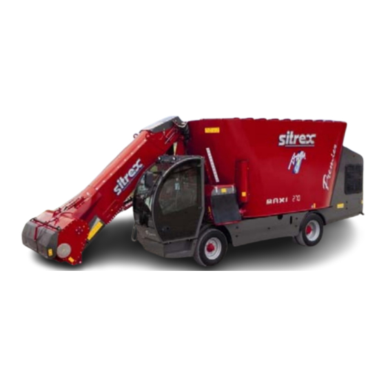
- Page 1 USE AND MAINTENANCE MANUAL SELF-PROPELLED MIXER FEEDER PREMIER - PREMIER MAXI FEEDSTAR Read this Manual carefully before using the machine REV. L 05/03/2015...
-
Page 2: Declaration Of Conformity
DECLARATION OF CONFORMITY Company ........... Address: Street............City........Prov......Tel.......Fax........Declares under its own responsibility that the machine: SELF-PROPELLED CUTTER-MIXER-FEEDER model: ..........serial number: ..........year of manufacture: ......Complies with the following European Directives: 2006/42/EC (Which repeals and includes Directives 89/392/EEC, 91/368EEC, 93/44/EEC and 93/68/EEC) 2004/108/EC (Which repeals Directive 89/336CE on Electromagnetic Compatibility) - Page 3 DESCRIPTION OF THE MINIMUM CONTENTS OF THE MANUAL This manual contains the description of the functioning and the instructions needed to correctly perform the main usage and routine and periodic maintenance operations on the machine. For ease in consultation, the manual is divided into easily identifiable chapters. The information given in this manual is intended for a professional user, who must have specific knowledge on how to use the machine, and must be suitably trained, instructed and authorized.
-
Page 4: Table Of Contents
1.2.1 Intended uses..................4 1.2.2 Description..................4 1.2.3 Foreseeable but prohibited us..............6 1.2.4 Technical specifications and parts identification PREMIER......8 1.2.5 Technical specifications and parts identification PREMIER MAX....10 1.3 NOISE LEVEL ...................12 1.4 STORAGE ....................12 1.5 PUTTING THE MACHINE BACK INTO SERVICE AFTER LONG STORAGE..12 1.6 SCRAPPING....................13... - Page 5 4.3.11 Windshield washer fluid tank...............50 4.3.12 Cutter loading belt check and tension adjustment........51 4.3.13 Unloading chain check and tension adjustment........52 4.3.14 Check and cleaning of anti-pollen filter, air conditioning and heating..53 4.3.15 Replacement of PREMIER MAXI auger gearbox oil.........55 Lubricants....................56 Tire Replacement..................57 Welding....................57 Replacement of cutter blades..............57...
-
Page 6: Information Regarding The Manua
If the manual is lost or damaged, ask the manufacturer (SITREX S.P.A Zona Industriale Viale Grecia, 22 - 06018 Trestina (PG) Italy) or dealer for a copy. This manual consists of 46 pages. -
Page 7: Machine Information
1.2 MACHINE INFORMATION 1.2.1 Intended uses This machine was designed and built exclusively for the cutting of silage and for mixing it with other products for animal feed and distributing it to the animals. Any use of the machine other than that described above is considered unauthorized and dangerous. - Page 8 1. Mixing tank 5. Unloading belt 2. Auger 6. Cab 3. Cutting knife 7. Cutter 4. Engine compartment 8. Mixing inspection ladder...
-
Page 9: Foreseeable But Prohibited Us
The SITREX S.p.A. company disclaims any and all objective and subjective liability when the rules of behavior given in the manual are not applied and followed. - Page 10 Trying to free the unloading belt, if it is jammed, by using shovels or pitchforks while the machine is in operation. Climbing on the top edge of the mixing tank. Lying under the machine to check on malfunctioning when the machine is in operation.
-
Page 11: Technical Specifications And Parts Identification Premier
1.2.4 Technical specifications and parts identification PREMIER - FEEDSTAR MODEL 7815 7670 7490 7630 7490 3560 3380 3150 2970 2800 3550 3300 3100 2960 2820 2900 2900 2550 2540 2550 2300 2300 2300 2300 2300 2200 2200 2200 2200 2200... - Page 12 Slow speed 10 km/h Fast speed 25 km/h Steering: Hydraulically assisted, 150 bar Front axle: Shock absorber Rear axle: Fixed Parking brake: Negative type acting on the rear axle Battery: 12V - 200Ah Alternator: 12v - 120A Tires: Front: 315/70 R15 Inflation pressure 8 bar Rear:...
-
Page 13: Technical Specifications And Parts Identification Premier Max
1.2.5 Technical specifications and parts identification PREMIER MAXI MODEL 9575 9445 9400 9450 3620 3350 2980 2800 3550 3350 3010 2910 2650 2650 2600 2315 2315 2315 2160 2160 2160 1285 1285 1285 Minimum turning radius of the front wheels... - Page 14 Slow speed 10 km/h Fast speed 20 km/h Steering : Hydraulically assisted 150 bar Front axle: Shock absorber Rear axle: Fixed Parking brake: Negative type acting on the rear axle Battery: 12V - 200Ah Alternator: 12v - 120A Tires : Front: 315/70 R22.5 Inflation pressure...
-
Page 15: Noise Level
Check the tires for wear; Check the lights and electrical system to make sure they are working properly; The SITREX S.p.A. company will not be liable for any damages or injuries caused by improper or inappropriate use of the machine. -
Page 16: Scrapping
Failure to observe safety regulations and precautions could cause accidents during operation, maintenance and repair of the machine. The SITREX company will not be liable for any damages or injuries caused by improper or inappropriate use of the machine. 1.7 SAFETY AND ACCIDENT PREVENTION REGULATIONS Carefully check the machine each time before putting into operation. - Page 17 Any modifications to the machine could cause safety problems. In this case the user will be solely liable for any accidents. SITREX mixer feeders are not approved for road traffic. Use them only within the farm. Check the tire pressure regularly and always keep inflated to the proper pressure depending on tire type and the nature of the soil.
-
Page 18: Safety, Information And Maintenance Signs And Labels
1.8 SAFETY, INFORMATION AND MAINTENANCE SIGNS AND LABELS Make sure that the safety pictographs are legible. Clean them with soap and water and a clean cloth. 1.8.1 Location of the safety, information and maintenance signs and labels 1.8.2 Description of the safety, information and maintenance signs and labels 1. - Page 19 3. ATTENTION - DANGER This machine must be used by a single operator. 4. ATTENTION – It is prohibited to climb on or be transported by the machine. 5. ATTENTION - Danger of shearing of hands. 6. ATTENTION - DANGER of entanglement of upper limbs.
- Page 20 9. ATTENTION - DANGER of electrocution. Be extremely careful of overhead power lines when using the cutter. 10. EXTINGUISHER Indicates where the fire extinguisher is located 11. ATTENTION - DANGER Chock wheels when the machine is stopped 12. ATTENTION - DANGER Do not stand within the machine’s operating range.
- Page 21 15. Oil tank. 16. Greasing points. 17. Use the required personal protective equipment. 18. Projecting parts warning stripes 19. ATTENTION - DANGER. Magnetic field Keep away: Persons with pacemakers or stimulators Persons with prostheses with metal objects ...
-
Page 22: Handling And Transporting
2. HANDLING AND TRANSPORTING Give maximum attention to safety during loading and unloading operations, which must be done by qualified personnel (slingers, lift truck operators, etc..). To anchor the machine, the eyes indicated by the pictographs must be used. (FIG.1). FIG.1 Procedure for loading onto a transport vehicle The machine must be loaded using ramps. -
Page 23: Instructions For Use
3. INSTRUCTIONS FOR USE The machine must be controlled exclusively from the driver’s seat, making sure that there are no persons or loose animals in the work area. In case of danger, apply the emergency brake. 3.1 CONTROLS, INSTRUMENTS AND WARNING LIGHTS Located in the inner front corner of the cab are, in order from top to bottom, the pressure gauge for... - Page 24 Behind the hand throttle is the joystick for the controlling the cutter. Remember that all operations carried out with the joystick must be done with the “person present” button held down. For applications with the cutter and the unloading belt press the button and then press it again to stop the application.
- Page 25 25 - Battery 9 – Air filter clogged 26 – Working taillights 10 – Hydraulic oil temperature 27 – Auger 2nd speed PREMIER 11 - TOP-CUT timer - in 27 - Auger 1st speed MAXI 12 - TOP-CUT timer - out 28 - Auger 1st speed PREMIER 13 –...
- Page 26 1 – Lever - reverse 2 - Lever - forward 1st gear 3 – 2nd gear 4 – Steering column tilt and extension adjustment handle 5 – Available 6 – Kill switch 7 – Ignition key 8 – Left turn signal 9 - Horn 10 –...
- Page 27 Located at the bottom right are the forward pedal (on the right) and the service brake pedal (on the left). main cabin controls, ventilation controls, stereo and courtesy light are located under the roof of the cab. A – Cab temperature control B - Front working lights C –...
-
Page 28: Driving The Mixer Feeder
3.2 DRIVING THE MIXER FEEDER Before starting the engine, check to make sure that: the machine does not have any loose parts. the cutter arm is about 500mm from the ground and with the protective guard lowered. the gear shift is in neutral, otherwise the machine will not start. Driving the mixer feeder is very much like driving a car! The left lever on the steering wheel has four positions: ... - Page 29 Adjusting the driver’s seat The driver’s seat is adjusted according to the driver’s weight so that they are in the proper driving position. ADJUSTMENT: Figure 1: Detail "A": Adjustment of seat spring stiffness. Detail "B": Adjustment of operator weight. Figure 2: Detail "C": Adjustment of seat back tilt. Figure 3: Adjustment of seat headrest.
-
Page 30: Diesel Engine
Wait until the engine has cooled before doing any type of maintenance work! The PREMIER mixer feeder diesel engine is located in the rear engine compartment. For optimal maintenance read the engine manual enclosed and pay attention to rules to be... -
Page 31: Weighing System
3.4 WEIGHING SYSTEM The weighing system control unit is located inside the driver’s cab. For operating procedures and for all other information see the weighing system user’s and maintenance manual supplied along with this manual. Remember to set the programming before starting the work cycle. 3.5 CUTTER The cutter arm makes possible first the cutting of the product with the knives on the front roller of the arm and the subsequent loading into the product mixing tank. -
Page 32: Loading
Start the machine and let the diesel motor warm up for a few minutes. Bring the machine near the product to be loaded. For the PREMIER – Press button no. 28 (pg.22) to start the mixing auger at low speed. -
Page 33: Cutting And Mixing Tank
The cutting-mixing auger in the PREMIER is driven by a motor controlled by switch no. 28 (pg.22) (working low speed) and switch no. 27 (pg.22), speed for final emptying, and regulated by variator no. -
Page 34: Tank Inspection Ladder
This system allows excellent cutting of fibrous products combined with the rotating action of the auger. The activating of the TOP-CUT knives is controlled with buttons no. 16-17 (pg.22). The former activates automatic operation, and the latter manual operation. The inserting and pause interval of the blades is programmed by setting the timers no. 11-12 (pg.22) on the dashboard. -
Page 35: Water Supply Pipe
3.12 WATER SUPPLY PIPE The pipe for supplying water (optional) is for those who need to wet dry products to avoid creating dust during mixing, or simply for the convenience of being able to connect a pump that draws water from a well, for example, to the lower edge of the tank, without having to climb a ladder with a water hose. -
Page 36: Road Use
3.16 ROAD USE The PREMIER mixer feeder cannot travel on public roads unless it is approved and registered. If your PREMIER mixer feeder is approved for road use, before entering a public road, carry out these operations: Put the cutter arm at the height above the ground as instructed by SITREX and install the cylinder stops (FIG.1). -
Page 37: Towing
3.17 TOWING The machine is equipped with permanent hydrostatic drive and a negative brake with hydraulic cylinder on the rear axle, and it can be towed only after putting the rear drive wheels in neutral. Place wheel chocks or connect to a suitable tractor with a rigid bar. ... -
Page 38: Maintenance
Proper maintenance keeps the machine always in efficient working order, significantly reducing breakdowns resulting in repairs and machine downtime. Always use original SITREX spare parts, and for extraordinary maintenance and repairs contact authorized SITREX shops directly. Carefully follow the maintenance schedule given in this manual. Take into account that the intervals given on pg. -
Page 39: Periodic Checks And Maintenance
Diesel fuel tank cleaning Clean unloading chain and loading belt Cutter rubber belt tension Unloading chain tension Tire pressure and wheel nut tightness Tighten pins, joints Battery electrolyte Lubrication at points indicated on pg.29 Hydraulic oil * Gearbox oil PREMIER MAXI... - Page 40 NO. 3 filters inside oil tank * Argo hydraulic oil filter Clean water radiators for diesel motor and hydraulic oil Coolant * Cab air filter Visual check of tightness of hydraulic lines and various nuts and bolts Lubrication cardan shaft MAXI Check presence of and emptying of water in...
- Page 41 C: Check P: Clean R: Replace L: Lubricate THE USED OILS AND THEIR FILTERS MUST BE COLLECTED AND DISPOSED OF IN COMPLIANCE WITH THE LAW (DPR 691/82 et seq.).
-
Page 42: Lubrication Points
4.2.1 Lubrication points Slide and leaf spring fulcrum pins Lifting cylinder joints on cutter arm. Belt roller, cutter rotor and conveyor bearings. - Page 43 Lifting cylinder joints on cutter support column. Cutter upper roller bearings. Unloading belt bearings ATTENTION: USE GREASE RECOMMENDED BY SITREX S.p.A...
-
Page 44: Engine Compartment
4.3 DIESEL ENGINE COMPARTMENT 4.3.1 Identification of components A- Water radiator-intercooler B – Air filter C - Silencer D – Hydraulic oil radiator... -
Page 45: Cleaning And Replacement Of The Air Filter
4.3.2 Cleaning and replacement of the air filter This filter is connected to the exhaust end of the silencer to have continuously the optimal cleaning of the filter and to take advantage of the depression caused by the exhaust. Open the side cover of the filter body. -
Page 46: Cleaning And Refilling Of Diesel Fuel Tank
Remove the safety cartridge, replace if necessary. Carefully clean the walls of the filter, put cleaned or new cartridges back in place and reattach cover in the correct position. 4.3.3 Cleaning and refilling of diesel fuel tank The diesel fuel tank is located at the right central part of the machine and has a cap with a key lock. -
Page 47: Diesel Fuel Filter
4.3.4 Diesel fuel filter See the diesel engine manual. It is located at the rear of the machine inside the engine compartment. 4.3.5 Diesel engine oil level dipstick Remove the rear guard underneath the hood (FIG.1). It is located at the lower right. Check the level, and replace the guard. FIG.1... -
Page 48: Replacement Of Hydraulic Oil And Tank Filters
4.3.6 Replacement of hydraulic oil and tank filters Turn off the engine, remove the left side guard and remove the filler cap (PART."E"). Place a container with a capacity of at least 180 liters underneath the drain plug (PART."C"). - Page 49 Refill (circa 170l) until the optical level gauge and thermometer (PART."B") is completely full. Replace the cap (PART."E") After any maintenance work is done on the hydraulic system, before starting the engine the pressure of pressure gauges 1 and 2 must be brought back to a pressure of 30 bar. To do this, put the accelerator (pg.
-
Page 50: Cleaning Of Diesel Engine Water And Oil Radiator
4.3.7 Cleaning of the diesel engine water and oil radiator To clean the diesel engine water radiator, remove the protective grille (FIG. 1) and blow with compressed air or wash with low pressure nozzle from the inside (FIG. 2) toward the outside. For further cleaning of the conveyor, remove the cover (FIG. - Page 51 To clean the hydraulic oil radiator use compressed air, blowing from the inside toward the outside. After cleaning open the conveyor and let impurities drain out. FIG.3 MAKE SURE TO CLOSE THE CONVEYOR TO ENGAGE THE SENSOR FOR FAN OPERATION (FIG.3).
-
Page 52: Topping Up The Diesel Engine Water Radiator
4.3.8 Topping up the diesel engine water radiator To access the radiator expansion tank, open the door at the rear left of the machine above the radiator grille, unscrew the cap and refill. 4.3.9 Checking the diesel engine timing belt To check or do maintenance on the diesel engine timing belt, use a screwdriver to open the two latches of the right rear door, do the necessary operations and refasten the latches. -
Page 53: Battery
4.3.10 Battery To access the battery, open the cover at the rear right. The removable battery disconnect key is also found at the side (Fig.1). FIG.1 DISCONNECT THE KEY EVERY TIME THAT MAINTENANCE IS DONE ON THE VEHICLE 4.3.11 Windshield washer fluid tank This is located at the rear of the cab. -
Page 54: Cutter Loading Belt Check And Tension Adjustment
4.3.12 Cutter loading belt check and tension adjustment FIG.1 TENSION ADJUSTMENT -FIG.1- The belt tensioners are located on the belt discharge shaft supports, near the cutter arm upper mounts. Lower the cutter arm and turn off the engine. Loosen the locknuts "A" of both tensioners. ... -
Page 55: Unloading Chain Check And Tension Adjustment
CENTERING ADJUSTMENT -FIG.2- If you notice that the belt moves sideways, you can make the refocusing through the regulator screw mounted on the engine mount tape located next to the mill on the right side. If you notice that the belt moves shifted to one side, it can be recentered by means of the screw regulator on the belt motor mount located next to the cutter on the right side. -
Page 56: Check And Cleaning Of Anti-Pollen Filter, Air Conditioning And Heating
START THE MACHINE AND HAVE THE CHAIN TURN A FEW TIMES AT VERY LOW SPEED. Turn off and remove the key from the dash, and recheck the tension of the chain or belt, to make sure that they are not under too much tension; if so, readjust it so as not to cause damage. - Page 57 Periodically check and blow out with compressed air the location of the air conditioning - heating unit under the driver's seat. Unscrew the knobs at the back of the seat and lift with the handle the cover where the seat is attached.
-
Page 58: Replacement Of Premier Maxi Auger Gearbox Oil
4.3.15 Replacement of PREMIER MAXI auger gearbox oil FIG.1 On the right side of the machine, located in the rear hood, there are the two auger gearbox tanks. Periodically check the oil level when the machine is cold. If the level is below the indicator, top up with suitable oil up to but not higher than the optical level gauge. -
Page 59: Lubricants
BRAKE FLUID LHM SUPER AGIP DIFFERENTIAL GEO PONTIAX TG AXLE FLUID SAE 90 EP GEARBOX OIL (corrisponde a ISO PREMIER MAXI (including prestage) VG.320 ) GEARBOX OIL IP TELESIA 220 PREMIER MAXI OIL FOR LOW TEMPERATURES (including prestage) PAKELO HYDROSINT... -
Page 60: Tire Replacement
4.5 TIRE REPLACEMENT To replace the tire, proceed as follows: Take the machine to a level surface and switch off the engine. Use a suitable key to unscrew half way all the tire lock nuts. Insert a suitable jack (with a load bearing capacity of at least 4,000 kg) under the chassis near the tire to be replaced. -
Page 61: Blockages And Flooding
4.9 BLOCKAGES AND FLOODING Should the auger or unload belt become blocked or flooded due to the special characteristics of the materials or should there be any anomaly in the transmission parts, the machine must be removed from its work position, the engine switched off and the ignition key removed from the dashboard for safety reasons. -
Page 62: Guarantee
This section describes the most likely problems, which may be solved with no need for qualified personnel. If you have doubt, please contact SITREX customer service. IF A WARNING LIGHT SWITCHES ON When a warning light switches on, this may mean: ... -
Page 63: Diesel Engine
5.2 DIESEL ENGINE TROUBLE POSSIBLE CAUSE REMEDY Check or replace battery. Battery down Check connections and commutator. STARTER DOES Electric connections damaged Replace – if the problem persists, NOT WORK Battery cutoff switch broken look to find the fault (*). Starter brushes worn Replace brushes : if the problem persists, contact workshop (*). -
Page 64: Hydraulic System
5.3 HYDRAULIC SYSTEM TROUBLE POSSIBLE CAUSE REMEDY Check oil level, check tightness of EXCESSIVELY NOISY Air in circuit. suction connections. PUMPS AND MOTORS Components worn. Repair or replace. Air in circuit. Bleed IRREGULAR Restrictor valve out of Recalibrate (*). STEERING calibration. -
Page 65: Oleodynamic Cylinders
5.4 OLEODINAMIC CYLINDERS TROUBLE POSSIBLE CAUSE REMEDY EXTERNAL OIL LEAKAGE Gaskets damaged. Replace gaskets (*). Insufficient oil pressure. See par.4.3. NOT ENOUGH POWER Internal oil leakage. Replace gaskets (*). TRANSPORTER BELTS PROBLEMA PROBABILE CAUSA RIMEDIO LATERAL SLIPPAGE Reposition belt. See par.4.3.9 TOO MUCH NOISE Recover tension. -
Page 66: Fuses
5.7 FUSES To avoid serious damage to electric system, replace fuses using new fuses with the same characteristics. The following relays are installed below the driver’s seat : F1 General-purpose positive output 15 for plant (60 Amp fuse) F2 General-purpose positive output 15 for plant (60 Amp fuse) ... - Page 67 Driver’s cab – below the roof - : Rearview mirror defrosting (7.5 Amp fuse) Three-speed solenoid for ventilation (20 Amp fuse) Courtesy light and car radio (15 Amp fuse) Front and back work lights (15 Amp fuse) ...
Need help?
Do you have a question about the PREMIER and is the answer not in the manual?
Questions and answers