Table of Contents
Advertisement
Quick Links
Advertisement
Table of Contents

Related Manuals for sitrex HAYMAKER HM/300


Summary of Contents for sitrex HAYMAKER HM/300
- Page 1 USE AND MAINTENANCE HAYMAKER HM/300...
-
Page 2: Table Of Contents
CONTENTS CHAPTER INTRODUCTION Introduction Warranty KEY TO THE SIGNS AND SYMBOLS USED IN THIS MANUAL AND THEIR POSITION ON THE MACHINE Warning signs Danger signs Information signs GENERAL SUMMARY OF SAFETY AND ACCIDENT-PREVENTION INSTRUCTIONS Instructions: 1 – 17 Instructions: 18 – 36 Instructions: 37 –... - Page 3 CHAPTER 1 GENERAL INTRODUCTION-WARRANTY...
-
Page 4: Introduction
The manual should always be kept to hand. It is particularly important to read chapter 3 on safety instructions. These instructions must always be heeded. If you are in any doubt, contact the Sitrex Assistance Centre or your nearest dealer. WARRANTEE On delivery, check that the machine has not been damaged during transport and that all the attachments are present. - Page 5 CHAPTER 2 GUIDE TO THE SIGNS AND SYMBOLS USED IN THIS MANUAL AND THEIR LOCATION ON THE MACHINE...
-
Page 6: Warning Signs
IMPORTANT These signs and symbols give information tom the operator on how to make the best use of the machine so as to prolong life, avoid damage, optimise work and, above all, to avoid injury to the operator and anyone within range of the machine. WARNING SIGNS Before beginning operations, read the instruction manual... - Page 7 Indicates a potentially dangerous situation which, if ATTENTION !!! not avoided, could cause death or severe personal injury, including dangers which are present when protection is removed. Indicates a potentially dangerous situation which, if CAUTION !!! not avoided, can provoke less severe or minor injuries.
- Page 8 Indicates that anyone coming within range of the moving tine arms will be seriously injured. Keep a safe distance from the machine. Indicates that there is a risk of crushing your hands. Keep your distance. Indicates that there is a risk of injury to feet from rotating tines.
-
Page 9: General Summary Of Safety And Accident-Prevention Instructions
CHAPTER 3 GENERAL SUMMARY OF SAFETY AND ACCIDENT-PREVENTION INSTRUCTIONS... - Page 10 GENERAL SUMMARY OF SAFETY AND ACCIDENT-PREVENTION INSTRUCTIONS Read all the directions carefully before using the machine. When in doubt, seek advice from the manufacturers The manufacturing company declines all responsibility for non-compliance with the following safety and accident-prevention instructions -Pay attention to the danger signs and symbols in this manual and on the machine. -Do not touch moving parts.
- Page 11 -Wear suitable clothes. Do not wear clothing which is loose or which could become entangled in rotating or moving parts. -Connect the machine to a suitably powerful tractor by using an appropriate lifting unit and in accordance with instructions. -Take maximum care when connecting and disconnecting the machine to and from the tractor.
- Page 12 -Before connecting or disconnecting the machine to or from the 3-point linkage, put the lifting unit lever into the locked position. -The connection pins on the machine must match the connection sockets on the lifting unit. -During transport, secure the lateral lifting arms with the appropriate chains and tighteners.
- Page 13 -Only clean and grease the cardan shaft when the power takeoff is disengaged, the engine is off, the parking brake is applied and the ignition key is removed. -When the cardan shaft is not in use, rest it on the support provided. -On disconnecting the cardan shaft, replace the protective hood on the power takeoff shaft.
-
Page 14: Product Identification
CHAPTER 4 PRODUCT IDENTIFICATION... -
Page 15: Technical Details
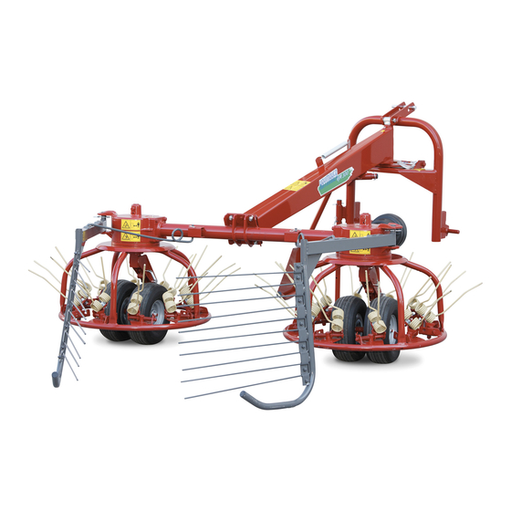
MAIN PARTS 1) 3 point linkage 2) Bar 3) Reduction unit 4) Axle 5) Driven box 6) Hay guard 7) Deflectors 8) Rotors 10) Cardan shaft protection 11) Rope 12) Parking stand 13) Wheel unit 14) Identification plate TECHNICAL DETAILS... -
Page 16: Location Of Signs And Symbols On The Machine
LOCATION OF SIGNS AND SYMBOLS ON THE MACHINE A) See drawing 10 p.8 B) See drawing 12 p.8 C) See drawing 13 p.8 D) See drawing 11 p.8 E) See drawing 9 p.8 F) See drawing 7 p.7 G) See drawing 1 p.6 H) See drawing 2 p.6 I) Identification plate... -
Page 17: Delivery Of Machine And Assembly
CHAPTER 5 DELIVERY AND ASSEMBLY... -
Page 18: Checking The Machine On Delivery
CHECKING THE MACHINE ON DELIVERY All parts are carefully checked before dispatch or delivery. On receiving the machine, ensure that it has not been demaged during transport. If demage has occurred, contact the dealer concerned. How the machine is lifted Will depende on the model and the type of packing. -
Page 19: Unpacking The Machine
UNPACKING THE MACHINE DANGER Life the machine using a forklift truck, crane or other suitable equipment of sufficient capacity after first checking the weight of the configurations in the table given below. Check the stability and positioning of the load on the forklift truck forks or crane hook. Keep the load as low as possible during movement for maximum stability and to ensure that the operator has maximum visibility. - Page 20 ASSEMBLY DANGER Assembly is highly dangerous and must be carried out in strict accordance with the following instructions. We recommend that assembly be performed by qualified personnel. We also recommend that assembly be carried out in a flat, open area with no people (particularly children) nearby who could be severely injured if they were to touch or move any parts of the machine.
- Page 21 ATTENTION Fit the bar (2) to the unit (1) Using the screw (3) and nuts (4). Make sure all these operations are correctly carried out before proceeding to the next phase. ATTENTION It is advisable to place a support under the front part of the bar (2) so as to avoid the machine tipping forwards.
- Page 22 DANGER In order to continue assembly safety and correctly, you must now raise the machine. You can use a suitably strong lifting device (crane / winch forklift) or a tractor with a 3- point linkage matching that of the machine. DANGER Lifting with a tractor.
- Page 23 The terms “left-hand side” and “right-hand side” are now introduced. They refer to the machine as observed from the position shown in the illustration opposite. CAUTION !!! Fit the large disk (5), the wheel (6), the small disk (7) and the washer (8) to the right-hand (3) and left-hand (4) arms.
- Page 24 ATTENTION Exercise extreme care when the machine Is suspended. Place a parallel tine (1) in its appropriate seating and fix it in place with the screw (3) washer (4) and nut (5). A divergent tine (2) is fitted in the same way. For the complete tine assembly see the following illustration.
- Page 25 ATTENTION Insert the parking stand (1) in the slot as shown and secure by inserting the split pin (2) in the hole (A) and the pin (3) in the hole (B). Lock pin (3) with clip (4). Make sure all these operations are correctly carried out before proceeding to the next phase.
- Page 26 CAUTION !!! Attach the right-hand (1) and left-hand (2) deflectors to their brackets and secure with split pins (3). Fit the spring arms (4) in their slots (for the various choices see page 35/3) and secure with split pins (5). Make sure all these operations are correctly carried out before proceeding to the next phase.
- Page 27 CAUTION !!! Put the cardan shaft support in the hole indicated and secure it using the flexible pin (2). Insert the clip (3) in the hole as shown and fasted it using the screw (4), the washer (5) and nut (6). CAUTION !!! When the machine is working, the cardan shaft support (1) must be...
-
Page 28: Adjustament, Preparation And Use
CHAPTER 6 ADJUSTMENT, PREPARATION AND USE... -
Page 29: Connection To The Tractor
INTRODUCTION DANGER Connection to the tractor is highly dangerous. Take great care and carry out the entire operation. in strict compliance with the following instructions. Nobody should go near the area between the tractor and the machine. Check that al warning and danger signs are in place and legible. Check that the tractor is in good running order. -
Page 30: Connecting The Cardan Shaft
CONNECTING THE CARDAN SHAFT DANGER More detailed information may be found in the Cardan shaft manual which, together with this manual, is an essential pan of the accident prevention documentation. It . is your. responsibility to read and comply with this documentation. If information given in this manual .should conflict with that given in the Cardan shaft manual, you should follow the instructions given by the Cardan shaft manufacturer. -
Page 31: Transport By Road
TRANSPORT BY ROAD After the machine has been attached to the tractor as previously described and before transporting it to or from fields or any other workplace, the following instructions should be heeded: ATTENTION After the machine has been attached to the tractor as previously described and before transporting it to or from fields or any other workplace, the following instructions should be heeded: Before setting off with the machine attached to the tractor, check the local road transport... -
Page 32: General Instructions For Field Use
GENERAL INSTRUCTIONS FOR FIELD USE Before starting work, familiarise yourself with the following general instructions: CAUTION !!! Before using the machine ensure that all safety precautions are taken. Check that all safety protection and guards are in place and working. Inspect the. - Page 33 GENERAL INSTRUCTIONS FOR USE DANGER In addition to the instructions given above, each time you have to make adjustments before and during work, we recommend moving the tractor and machine to a firm, flat open area. Before getting off the tractor to make adjustments, follow this procedure exactly: 1) Lower the machine until its wheels touch the ground (this is recommended every time the tractor is stopped for any reason).
- Page 34 Exercise maximum care and heed the safety rules mentioned above. The right-hand and left-band wheel arms (1) (2) have three operating positions: A, B and C. C) For raking when hay is very dry and sparse. B) For raking in remaining conditions. For spreading and turning in normal pasture conditions.
- Page 35 Tine positions The tines have positions: A: Inner hole (nearer the wheel): for raking. B: Outer hole: for spreading and turning two operating (nearer the raking far spreading To change tine position, you should lever against support (C) using a screwdriver or lever and move the tine backwards until the pin comes out of the hole.
-
Page 36: Operating Examples
OPERATING EXAMPLES IMPORTANT 1) During operation the machine must only turn to the left. You may turn to the right only when the machine has been raised by the tractor's hydraulic lifter. 2) Raking: Tines: In the raking position (see note 4 on page 35) Deflectors: Adjust according to the amount of hay. - Page 37 4)Working alongside embankments and ditches: When working alongside embankments and ditches, the rotor nearest the embankment or ditch must have its tines in the raking position and the-deflector fitted. The other rotor has no deflector fitted and the tines should be in the spreading position.
-
Page 38: Temporary Parking
TEMPORARY PARKING ATTENTION If the machine has to be temporarily parked (for extended periods see page 42) proceed as follows, bearing in mind the instructions in Chapter 3. Before getting off the tractor, follow this procedure exactly: Choose a flat, hard open space, away from frequented areas if possible. Lower the machine until its wheels touch the ground (this is recommended every time the tractor is stopped for any reason). - Page 39 Disengage the cardan shaft and place it on its rest. Withdraw the split pin (2) from the pin (3) and remove this pin. The tie rod (1) is now disconnected from the machine. CAUTION Withdraw the split pin (3) and remove the lateral arms (2) from the pins (1) on the 3-point linkage.
-
Page 40: Maintenance
CHAPTER 7 MAINTENANCE... -
Page 41: Maintenance Directions
MAINTENANCE DIRECTIONS DANGER !!! All cleaning, lubrication and maintenance operations must be carried out with the machine disconnected from the tractor. In an emergency with the machine still connected to the tractor, switch off the .engine, apply the parking brake, disengage the power takeoff and remove the ignition key from the instrument panel. -
Page 42: Laying Up For Extended Periods
GENERAL INSTRUCTIONS FOR REPAIR WORK DANGER !!! Any repair work must be carried out with the machine at rest and disconnected from the tractor. Do not carry out welding without authorisation and instructions from, the manufacturers. Disconnect the machine from the tractor before any welding work in' order not to damage the battery. -
Page 43: Maintenance Points
MAINTENANCE POINTS Number Quantity Description Operation Every… Product Notes hours to be used 3-point Grating Grease linkage pivot Gearboxes Greasing Grease Power takeoff Cleaning Additives • shaft Greasing Grease Arm linkage Cleaning Additives • pins Greasing Grease Tyres Check Compressor 45 psi pressure General checking of bobs, security pins and split pins to be carried au... - Page 44 CARDAN SHAFT MAINTENANCE More detailed information may be found in the Cardan shaft manual which, together with this manual, forms an essential part. of the accident-prevention documentation. It your responsibility to read and comply with this documentation. If information given in this manual conflicts with that given in the Cardan shaft manual, you should follow the instructions given by the Cardan shaft manufacturer.
- Page 45 NOISS AND VIBRATION Noise affecting the, tractor driver (from the machine only) is less than 70 db. Vibration from the machine affecting the upper body and limbs of the driver is insignificant and is lower than the values given in Point 3.6.3 of Enclosure 1.of the Machine Directives (89/392/EEC, 91/386/EEC).
- Page 46 Zona Industriale-Viale Grecia, 8 06018 TRESTINA-(Perugia)-ITALY Tel. +39.075.8540021-Telefax +39.075.8540523 e-mail: sitrex@sitrex.it www.sitrex.com...
Need help?
Do you have a question about the HAYMAKER HM/300 and is the answer not in the manual?
Questions and answers
Fit spring on hm300
To fit a spring on the Sitrex Haymaker HM/300, follow these steps:
1. Fit the spring arms into their designated slots.
2. Secure each spring arm with a split pin.
Refer to page 35/3 for the various choices of spring arms. Ensure all steps are correctly completed before proceeding.
This answer is automatically generated