Table of Contents
Advertisement
Quick Links
Advertisement
Table of Contents

Related Manuals for sitrex MK/10


Summary of Contents for sitrex MK/10
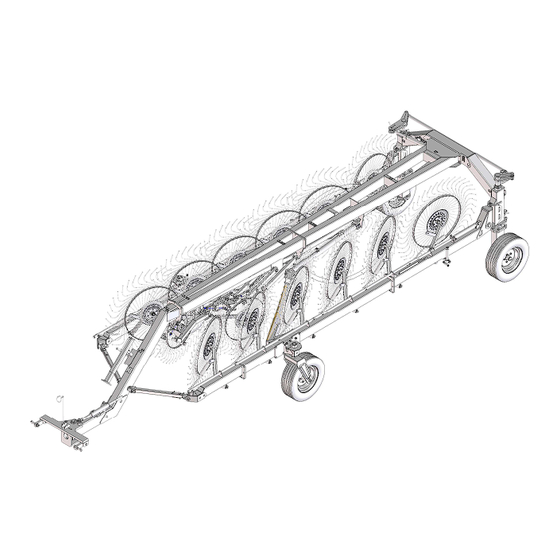
- Page 1 ASSEMBLY, USE AND MAINTENANCE MK/10-12 STEERABLE 07/2017...
-
Page 3: Warranty
WARRANTY When the machine is received, regardless of how it is delivered (in a crate, partially assembled, assembled, etc.), the customer must check to make sure that it is in good condition and that all components are present. To report any damage, any missing parts or anything else that compromises the perfect condition of the machine, submit a written claim to the sales agent and/or the distributor and/or the manufacturer within eight days from the delivery date. - Page 4 GENERAL SUMMARY OF SAFETY AND ACCIDENT PREVENTION INSTRUCTIONS. Read all the instructions and rules carefully before using the machine. If you have any doubts, contact the dealer, the distributor or the manufacturer. The manufacturer disclaims all liability for non-compliance with the safety and accident prevention instructions and rules.
-
Page 5: Specifications
SPECIFICATIONS SPECIFICATIONS MKE/10 MKE/12 Number of Finger Wheels Finger Wheels diameter (standard) 1400 mm - 55" 1400 mm - 55" Finger Wheel Tine Diameter (standard) 7 mm - 0,28" 7 mm - 0,28" Finger Wheels diameter (optional) 1525 mm - 60" 1525 mm - 60"... -
Page 6: Machine Identification Data
GUIDE TO THE MEANING OF SIGNS AND SYMBOLS IMPORTANT These signs and symbols give the operators information on how to make the best use of the machine so as to prolong its life, avoid damage to the machine and to objects, optimize work and, above all, on how to avoid injury to the operator and to anyone who is within the operating range of the machine. - Page 7 MEANING AND DESCRIPTION OF THE LABEL 1) Plate identification 2) Logo SITREX (for sections) 3) Logo SITREX (for drawbar) 4) Maximum speed limit 5) Do not climb on the machine or on the tractor in an improper way 6) Red reflector...
- Page 8 MEANING AND DESCRIPTION OF THE LABEL Warns against the potential and serious danger of crushing hands. Keep your distance. 11) Warns against the potential and serious danger of injury to the feet. Keep your distance. 12) Warns against the potential and serious danger of injury to the body.
- Page 9 NOTE: VERY IMPORTANT When the machine is received, regardless of how it is delivered (in a crate, partially assembled, assembled, etc.), the customer must check to make sure that it is in good condition and that all components are present. To report any damage, any missing parts or anything else that compromises the perfect condition of the machine, submit a written claim to the sales agent and/or the distributor and/or the manufacturer within eight days from the delivery date.
- Page 10 Assembly Instructions Examples of general measurements for identifying assembly accessories according to type. To make it easier to identify the assembly accessories (nuts, bolts, washers, pins, etc.) on the basis of the general dimensions and the type, we provide a diagram that shows you the accessory parts to which the measurements refer as given in the various steps of assembly.
- Page 11 Examples of general measurements for identifying accessories for assembly according to type. For tightening torques, see the table below (the class of the material is normally stamped on the head of the bolts).
- Page 12 General assembly instructions for all models in the MKE series. regards indicating right/left, they are understood to be attributed observing the machine from point A (behind the machine) looking forward. The machine must be assembled in a suitable area, done by qualified personnel equipped with the proper clothing, protective equipment and tools necessary for the job.
-
Page 14: Assembly Sequence
ASSEMBLY SEQUENCE Sometimes the figures illustrating the assembly of the standard machine and valid also for this steering version do not faithfully represent the machine’s appearance, but in essence they are entirely valid (see example below). DANGER Connect the supports 1-2 (RH-LH) to the crosspiece assembly 3 using screws 4 and nut 5. - Page 15 3) DANGER Attach the wheel hubs 1 to vertical supports 2-3 (RH-LH) using bolts 4 and nuts 5. In this step, you will use: Item 5: 6 bolts M16x50 (0.63”x1.97”) Item 6: 6 nuts M16 (0.63”) 4) DANGER Attach the wheels 1 to the hubs 2 and fasten with the special nuts 3.
- Page 16 5) DANGER The tie rod 1 is preassembled to the right size for it to be attached to seats A-B on the crosspiece assembly. Connect tie rod 1 to seats A-B on the crosspiece assembly the screws 2, washers 3 and nuts 4. In this step, you will use: Item 2: 2 screws M20x100 (0.78”x3.93”) Item 6: 2 washers ø21 (ø0.82”)
- Page 17 DANGER Check that manufacturer assembled bushings A to their seats on sections 1-2 (RH- LH). Now attach sections 1-2 (RH-LH) to the seats on the vertical supports 3-4 (RH-LH) using the pin 5, spacer 6, washers 7 and nuts 8. Once sections 1-2 are attached, set them on a support.
- Page 18 7) DANGER Tube B serves to hold together the spring and the other assembled parts, and it must be removed when the rake wheel lifting pipes are assembled (see step 12). Now attach sections 3-4 (RH-LH – 40kg/155lbs) to sections 1-2 (RH-LH) using bolts 5 and nuts 6.
- Page 19 8) DANGER Insert the nylon bushings 5 into the openings in sections 1-2 (RH-LH). Place spacer 4 on the pins of the wheel units 3. Insert the wheel units 3 into the openings in sections 1-2. Attach the flange 6 onto the pins of the wheel units 3 using the spring pins 7.
- Page 20 You have now reached this stage of the assembly. The machine rests on its wheels and thus has good stability. However, continue to use great caution during the rest of the assembly, so as to work safely. In order to work better, spread apart the right and left sections of the machine.
- Page 21 2325 12) DANGER Check to make sure the manufacturer has correctly secured the bushings B with retaining rings C on brackets A on all the RH and LH sections. MKE/10-12 - First of all, tube D must be removed (it will not be reused). To do this, remove bolt 1 and nut 2 that fasten it to bracket E.
- Page 22 13) DANGER Carry out this operation very carefully and with suitable lifting equipment because the drawbar 1 is heavy and bulky. Weight 190kg/440lbs. Attach the drawbar 1 to the 2 using bolts 3 and nuts 4. crosspiece assembly Insert support 5 in the seat A. Attach the rear reflector 6 to the support 5. ATTENTION!! In this step, you will use: MAX TIGHTENING COUPLES...
- Page 23 14) DANGER Carry out this operation very carefully and with suitable lifting equipment because the drawbar 2 is heavy and bulky. Weight 135kg/297lbs plus the preceding drawbar. To work safely and make the next assembly easier, set the drawbar 2 on a support A. Attach drawbar 2 to drawbar 1 using bolts 3 and nuts 4.
- Page 24 15) DANGER Carry out this operation very carefully and with suitable lifting equipment because the drawbar 2 is heavy and bulky. Attach drawbar 2 to drawbar 1 using bolts 3 and nuts 4. Attach the stand 5 to seat on drawbar 2 using the pin 6 and clip 7. Attach the canister 8 to seats B on the drawbar 2 using bolts 9, washers 10 and nuts 11.
- Page 25 16) DANGER Insert the grease nipple 2 into the opening in drawbar 1. Insert the nylon bushings 3 into the openings in drawbar 1. Couple support 4 to drawbar 1 using the pin 5 , the washers 6, the nuts 8 and spring pin 9. In this step, you will use: Item 1 grease nipple M8...
- Page 26 18) DANGER The safety arms 1 are made up of an inner part A and an outer part B assembled together by the manufacturer using the pin and clip C (same as pins 4 and clips 5). In addition, in the fork of the inner part A you will find preassembled by the manufacturer the pin 4 and clip 5, whereas on the fork of the outer part B you will find preassembled the bolt 2 and nut 3.
- Page 27 19) DANGER Attach the opening arms 3-4 (RH-LH) to sections means counterplates 5, bolts 6 and nuts 7. In box theoretic measurements given assembly of arms 3-4 and counterplates 5. At this stage do not fully tighten nuts 7, because when cylinders are attached (see step 24) it may...
- Page 28 21) DANGER Insert brackets 2 in the slots A in all the pipes (RH-LH). Attach the chain 3 at all the brackets 2 using the bolt, washer 5 and nut 6. In this step, you will use: Item 2: 10-12 chain brackets - Item 3: 10-12 chains, length 820mm (32.3”) Item 4: 10-12 bolts M10x25 (0.4”x1”) - Item 5: 10-12 washers ø11-30x2.5 (ø0.43”- 1.18”x0.1”)
- Page 29 Item 2: n° 1 RH special arm Item 3: n° 1 LH special arm HEAVY CROP - OPTIONAL 22) DANGER In this step, you will use: Item 1: 20-24 nylon bushings ø35-42x26 (ø1.38”-1.65”x1”) Item 4: 10-12 washers ø35-50x5 (ø1.38”-1.97”x0.19”) Item 5: 10-12 spring pins ø8x50 (ø0.31” x 1.97”) Item 8: 60-72 bolts M10x25 (0.39”x1”) Item 9: 60-72 split washers ø10.5-17x2.5 (ø0.41”-0.67”x0.1”) Item 10: 60-72 nuts M10 (0.39”)
- Page 31 23) DANGER Hook X on spring 1 is more closed than hook Y. Hook Y (the more open one) should be inserted into hole Z in the lever of arms 2-3 (RH-LH). First of all pass chain K, which is screwed onto the rake wheel lifting pipes, through the spring 1.
- Page 32 24) DANGER Note: Spread open the machine in order to have more room to work in. There are two hydraulic cylinders complete with valves, one set up for the RH side indicated by reference 1 and one for the LH side indicated by reference 2. The assembly is correct when the valve is on the upper part of the cylinder and when holes A-B are facing the outside of the machine.
- Page 33 25) DANGER Extend the hose 1 along the drawbar until the female end is near bracket A. Connect the female end of hose 1 to the T coupling 2. Connect the elbow couplings 3 to the T coupling 2. The assembled hose and couplings unit 1-2-3 are placed underneath bracket A so that the couplings 3 are at the back of it.
- Page 34 26) DANGER Apply washers 2 and nipples 3 to holes A on the check valves of the RH and LH cylinders. Apply washers 2 and nipples 3 to holes B on the flow divider. Connect the curved end of hoses 4 to nipples 3 on the cylinder check valves. Connect the other end of hose 4 to nipples 3 on the flow divider without fastening completely.
- Page 35 27) DANGER Apply washers 2 and nipples 3 to holes C on the check valves of the RH and LH cylinders. Connect the curved end of hoses 4 to nipples 3 on the cylinder check valves without tightening completely. Connect the other end of hose 4 to couplings D located underneath the flow divider bracket without fastening completely.
- Page 37 28) DANGER (see drawing on preceding page) Connect coupling 1 to cylinders A using washers 2 and bolts 3. Apply nipple 4 to coupling 1. Apply washer 2 and valve 5 to nipple 4. Apply washer 2 and nipple 6 to valve 5.
- Page 39 29) DANGER Send hose 11 under bracket A and continue to secure it with collars 3 and screws 4. Apply washer 6 and nipple 5 to hole B on the flow divider. Bring the female end of hose 2 near the nipple and extend it along the drawbar toward the front of the machine parallel to hose 1 already assembled.
- Page 41 30) DANGER Continue to secure hose 5 with collars 3 and screws 4. Continue to secure hoses 1-2 with collars 6, clamps 7 and bolts 8. Hoses 1-2-5 must be placed on the proper support. Note: (see box A) before fixing definitely the hoses 1-2 with the collars 6 the lock 7 and the screw 8, mount the steering kit see point 40.
- Page 43 31) DANGER The steering kit hoses 1 have to be extended on the drawbar, starting from the front to the rear of the machine. On the front side you should put the cylinder near the A valve. Fit pins 11 into proper seats and fasten with screws 9 and nuts 10. Then you should assemble the rear cylinder of the steering kit 1 on its own seats of the rear crosspiece using washer 2, screw 3, pin 4 and split pin 5.
- Page 44 M8x20 M10x25 LAMPEGGIANTE RH SIDE / LH SIDE / DROITE GAUCHE CAVO ATTACCO AL TRATTORE CAVO LUCE TARGA...
-
Page 45: Before Using
ADJUSTMENT, PREPARATION AND USE BEFORE USING DANGER !!! Beginning of season after winter storage. Before running the machine, the operator must have read and understood all the sections of this Manual Before beginning work, check to make sure that the machine is in good operational condition with all lubricating oil levels correct and all work parts subject to wear and tear in good working condition. - Page 46 OPERATIONS TO BE DONE BEFORE STARTING TO WORK. First all, rotate safety arms 1 from transport position A-C to working position A-B. During working phase, valve applied to the finger wheels lifting cylinders must be open. Warning: arms 1 are not removed and cylinders opening...
- Page 47 HOW TO MAKE ADJUSTMENTS. If you find that the rake wheels 1 are heavy, i.e. they dig into the earth too much, you can move link A of chain 2 connected to spring 3 to the link before it, thus with chain 2 shorter it puts spring 3 under greater tension, lightening the rake wheel 1.
-
Page 48: Hitching To Tractor
HITCHING TO TRACTOR Hitching to the tractor is a very dangerous phase. Make sure that you carry out this operation following the instructions. Hitch the baler to the tractor as follows: 1. Make sure the tractor is rated for the machine it has to tow. 2. - Page 49 Set the support feet in the transporting position. Connect the hydraulic pipes to the tractor distinguishing between those for the opening system and those for the lifting of the splitter wheels. WHEELS Always check them for wear and pressure of the wheels (3,5 Bar – 50 PSI). WORK POSITION DANGER !!! When the machine is running, the operator MUST be in the driver’s seat because it is only from...
- Page 50 ADJUSTMENTS The adjustments to carry out on the hay rake are the following: windrow width, working width and adaptation of the rake finger wheels. WINDROW WIDTH ADJUSTMENTS Turn the crank to adjust the windrow width. In this way the last two rake wheels can be adjusted to obtain a wider windrow. WORKING WIDTH ADJUSTMENTS Your hay rake has an infinite number of working widths from the transport position to its maximum width that according to the different models.
-
Page 51: Steering Control
STEERING CONTROL It’s possible to set the sensibility of the steering system moving the head of the rear cylinder and fixing it to one of the holes on the steering lever. More the hole is rear, more the system is sensible. The standard position for the cylinder head is on the second hole. - Page 52 STEERING FUNCTION To activate the steering function of the rake, operate as follow: - de-insert the pivots on the rear of the machine and block it as shown in the picture (A->B). - close the bypass tap on the cylinder which regulates the steering (C->D). The steering system is now operative.
- Page 53 SELF-STEERING FEATURE WHEN ON ROAD For the transport on public roads, adhere to the dispositions on the circulation in force in the Country in which the machine is being used. For security reasons it is necessary to disengage the steering system for the transport on public roads.
- Page 54 SOLUTION TO POSSIBLES SKEWINGS OF THE RAKE Is possible that the rake skews from the tractor. To solve the problem and for restore the alignment, proceed as follows (eventually being helped by a second operator): - Steer carefully the tractor for obtain the perfect alignment of the rear safety pivot (A). - Insert the safety pin on the rear wheels (A).
- Page 55 - Drive straight for a certain distance with the tractor and the rake (C) to obtain the perfect alignment of the machines. - Close the bypass on the rear cylinder (D). - De-insert and lock the safety pin of the rear wheels (A). The implant is now aligned and functioning.
- Page 56 PRESSURIZING THE STEERING SYSTEM The steering cylinders hydraulic circuit is pressurized at 30 bar by the manufacturer. The steering cylinders hydraulic circuit must be mounted on the machine without doing anything to the hydraulic fittings. To restore any small oil leaks from the system, use the pressure gauge coupling (A) located on the front cylinder.
- Page 57 UNHITCHING THE MACHINE FROM THE TRACTOR DANGER !!! Park the machine on flat, level ground. Carry out the operations in the following order: 1) Secure the machine with chocks under the wheels. 2) Disconnect the hydraulic hoses and electric wires. 3) Secure the hydraulic hoses and electric wires in the bracket.
-
Page 58: General Instructions For Maintenance
GENERAL INSTRUCTIONS FOR MAINTENANCE REPAIR WORK Repair work must be done with the machine stationary and detached from the tractor. Do not do any welding without the authorization of and/or instructions from the manufacturer. With the machine on the ground, release the pressure of the hydraulic circuit and allow the machine to cool down. - Page 59 MAINTENANCE POINTS AND INSTRUCTIONS Every x Pos. Qty. Description Operation hours Rear crosspiece Lubricate 50 (A) Opening tie rod Lubricate 50 (A) Vertical support Lubricate Rear wheel hub Lubricate Section joint pin Lubricate 50 (A) 10-12 Rake wheel arm joint Lubricate Pirouetting wheel support Lubricate...
-
Page 60: Maintenance - As Required
MAINTENANCE - after 10 hours of service After the first hours of operations, check to make sure that all nuts and bolts are well tightened. All hardware should be checked on a routine basis after every 10 hours of service. MAINTENANCE –... -
Page 61: Noise And Vibrations
NOISE AND VIBRATIONS The machine does not have any drive components, so the only noises it makes are that of the teeth dragging on the ground and those caused by machine vibrations, therefore the noise of the tractor always covers that of the machine. INFORMATION ON SCRAPPING THE MACHINE The machine consists mainly of ferrous material, which must be disposed of according to the regulations in force in the country concerned. - Page 62 Zona Industriale-Viale Grecia, 8 06018 TRESTINA-(Perugia)-ITALY Tel. +39.075.8540021-Telefax +39.075.8540523 e-mail: sitrex@sitrex.it www.sitrex.com...
Need help?
Do you have a question about the MK/10 and is the answer not in the manual?
Questions and answers