Delta Ultron DPM Gen2 Series User Manual
Hide thumbs
Also See for Ultron DPM Gen2 Series:
- User manual (160 pages) ,
- User manual (193 pages) ,
- User manual (174 pages)

Related Manuals for Delta Ultron DPM Gen2 Series


Summary of Contents for Delta Ultron DPM Gen2 Series
- Page 1 The power behind competitiveness Delta UPS Ultron Family DPM Gen2 Series, Three Phase, CE/ UL 1250/ 1263 kVA User Manual www.deltaww.com...
- Page 2 Failure to heed these instructions and warnings will void the warranty. Copyright © 2023 by Delta Electronics Inc. All Rights Reserved. All rights of this User Manual (“Manual”), including but not limited to the contents, information, and figures are solely owned and reserved by Delta Electronics Inc.
-
Page 3: Table Of Contents
Table of Contents Chapter 1 : Important Safety Instructions ................. 8 Installation Warnings ................ 8 Connection Warnings ............... 8 Usage Warnings ................10 Storage Warnings ................12 Standard Compliance ..............12 ... - Page 4 Installation Environment ..............58 UPS Installation ................60 Wiring ....................65 5.4.1 Pre-wiring Warnings ............... 65 5.4.2 Single Input to Dual Input Modification ........70 Ultron DPM Gen2 Series...
- Page 5 5.4.3 Single Unit Wiring ................72 5.4.3.1 Single Input (Single Unit) ..............74 5.4.3.2 Dual Input (Single Unit) ..............78 5.4.4 Parallel Units Wiring ............... 80 External Battery Cabinet Connection Warnings ......82 ...
- Page 6 Chapter 8 : Optional Accessories ................... 158 EMS Function on the LCD Screen ..........160 BMS Function on the LCD Screen ..........163 MFC Function on the LCD Screen ..........165 Ultron DPM Gen2 Series...
- Page 7 Chapter 9 : Maintenance ....................167 Appendix 1 : Technical Specifications ................172 Appendix 2 : Warranty ..................... 175 ...
-
Page 8: Chapter 1 : Important Safety Instructions
5.2 Installation Environment maintenance. Please refer to • Only authorized Delta engineers or service personnel can perform installation and maintenance. If you want to install the UPS by yourself, please install it under the supervision of authorized Delta engineers or service personnel. - Page 9 Each breaker mentioned above should be configured with an configured by auxiliary switch. The auxiliary switch must have a normally Delta service open (NO) contact and a normally closed (NC) contact personnel) connected to the UPS system cabinet’s dry contacts to detect 4.1.8 External...
-
Page 10: Usage Warnings
(that have serious surge current) to the UPS, it needs to be de-rated according to on-site applications. For such special applications, please contact Delta service personnel for the accurate UPS sizing. The UPS is not suitable for connecting with any asymmetrical loads. For the load suitability, please contact Delta customer service before purchasing. - Page 11 Please note that the battery grounds mean any battery pole (+/ -) connecting to the ground. • You must contact Delta customer service if any of the following events occurs: 1. Any liquid is poured or spilled on the UPS.
-
Page 12: Storage Warnings
The allowable storage temperature is below 70°C (158°F) and relative humidity is below 95%. Standard Compliance • EN 62040-1 • EN 62040-2 Category C3 • EN 61000-4-2 • EN 61000-4-3 • EN 61000-4-4 • EN 61000-4-5 • EN 61000-4-6 Ultron DPM Gen2 Series... -
Page 13: Chapter 2 : Introduction
Chapter 2 : Introduction General Overview The DPM series UPS, a three-phase three-wire on-line uninterruptible power supply (hereafter referred to as 'UPS'), is a dedicated design for large scale power systems such as data centers, communication systems, satellite systems, network rooms, medical systems, emergency systems, monitoring systems and factory facilities. - Page 14 410 PCS ⓫ Belleville Washer 410 PCS TMS Sensor Cable (only for 1263kVA UPS) 85 PCS ⓬ Cable Tie (only for 1263kVA UPS) 20 PCS ⓭ Power Module 2 PCS ⓮ Power Module 3 PCS ⓯ Ultron DPM Gen2 Series...
-
Page 15: Functions & Features
Functions & Features • True on-line double-conversion UPS adopts DSP chip and IGBT technology to protect your sensitive electronic equipment from power interruption. • Wide AC input voltage range (285 Vac ~ 477 Vac) reduces frequent transfer from On-Line mode to Battery mode to save battery consumption and prolong battery life. -
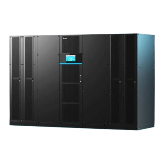
Page 16: Exterior & Dimensions
Exterior & Dimensions 5.3 UPS Installation Please follow to assemble the UPS system cabinet and power modules. After assembly, the UPS exterior and dimensions are as follows. (Figure 2-1: 1250/ 1263kVA UPS_ Exterior & Dimensions) Ultron DPM Gen2 Series... -
Page 17: Ups System Cabinet
UPS System Cabinet 2.5.1 Front View (Figure 2-2: 1250/ 1263kVA UPS_ Front View of the UPS System Cabinet) (Figure 2-3: 1250/ 1263kVA UPS_ How to Open the UPS System Cabinet’s Three Front Doors) -
Page 18: Side View
& cover removal, maintenance and operation. If you want to execute any action mentioned above by yourself, the action must be under the supervision of authorized Delta engineers or service personnel. After you remove the UPS system cabinet’s right and left front panels, you will see the wiring terminals that need to connect to the power modules. - Page 19 (Figure 2-5: 1250/ 1263kVA UPS_ Wiring Terminals that Need to Connect to the Input Power, External Battery Cabinet and Critical Loads)
-
Page 20: Power Modules
UPS system cabinet and the remaining two at the left- hand side of the UPS system cabinet. Each power module’s capacity is up to 252.6kVA/ 250kW. (Figure 2-6: 1250/ 1263kVA UPS_ Front View of the Power Modules) Ultron DPM Gen2 Series... -
Page 21: Side View
& cover removal, maintenance and operation. If you want to execute any action mentioned above by yourself, the action must be under the supervision of authorized Delta engineers or service personnel. The power modules must be connected with the UPS system cabinets. Please refer... - Page 22 (Figure 2-8: 1250/ 1263kVA UPS _ Wiring Terminals that Need to Connect to the Left-hand Side of the UPS System Cabinet) Ultron DPM Gen2 Series...
- Page 23 (Figure 2-9: 1250/ 1263kVA UPS _ Wiring Terminals that Need to Connect to the Right-hand Side of the UPS System Cabinet)
-
Page 24: Tri-Color Led Indicator & Buzzer
For information about the 10” color touch panel, please refer to & Settings The buzzer is located at the rear of the UPS system cabinet’s middle front door. Please refer to the figure below. (Figure 2-11: Buzzer Location) Ultron DPM Gen2 Series... - Page 25 Table 2-1: Tri-color LED Indicator, UPS Operation Mode & Buzzer Tri-color LED Status Meaning Indicator Indicates the UPS is operating in one of the • following modes. Text on the LCD Screen UPS Operation Mode (upper-right corner) On-Line Mode ‘On-Line’ Green ECO Mode ‘ECO’...
-
Page 26: Chapter 3 : Operation Modes
Conversion mode and Energy Recycle mode. NOTE: The UPS must be connected with an external maintenance bypass cabinet (user-supplied, handled and configured by Delta service personnel). For information regarding the external maintenance bypass 1.2 Connection Warnings cabinet, please refer to 2. -
Page 27: On-Line Mode
On-Line Mode In On-Line mode, the main AC source supplies AC power via the external maintenance bypass cabinet’s Input Breaker (Q1) to the rectifier, and the rectifier converts the AC power to DC power and supplies the DC power to the inverter. In the meantime, the rectifier provides charging power to the batteries. -
Page 28: Battery Mode
Breaker (Q4). During the conversion process, output voltage remains the same. During Battery mode, the UPS’s tri-color LED illuminates yellow and the text ‘Battery’ appears in the upper right corner of the LCD screen. (Figure 3-2: Battery Mode Diagram) Ultron DPM Gen2 Series... -
Page 29: Bypass Mode
Bypass Mode When the inverter encounters abnormal situations such as over temperature, overload, short circuit, abnormal output voltage or low battery, it will automatically shut itself down. If the UPS detects the bypass input is normal, it will automatically switch to Bypass mode to protect the connected critical loads from power interruption. -
Page 30: Manual Bypass Mode
During Manual Bypass mode, the UPS’s input power is completely cut off, and the critical loads are not protected. At the moment, the UPS’s tri-color LED and LCD screen are both off. (Figure 3-4: Manual Bypass Mode Diagram) Ultron DPM Gen2 Series... -
Page 31: Eco Mode
ECO Mode After the UPS is manually set as ECO mode via the LCD, the UPS will work in Bypass mode if bypass input voltage and frequency are within ± 10% of the rated voltage and ± 5 Hz of the rated frequency respectively. Otherwise, the UPS will run in On-Line mode. -
Page 32: Green Mode
UPS. During Green mode, the UPS’s tri-color LED illuminates green and the text 'Green' appears in the upper right corner of the screen. (Figure 3-6: Green Mode) Ultron DPM Gen2 Series... -
Page 33: Clean Mode
Clean Mode After the UPS is manually set as Clean mode via the LCD, the system will automatically detect the output status to let the inverter provide active filter function to compensate harmonics, correct power factor and reduce bypass reactive current to improve overall power quality. -
Page 34: Frequency Conversion Mode
Please note that, once the inverter shuts down, there is no bypass output. During Frequency Conversion mode, the UPS’s tri-color LED illuminates green and the text ‘Frequency Conversion’ appears in the upper right corner of the screen. (Figure 3-8: Frequency Conversion Mode) Ultron DPM Gen2 Series... -
Page 35: Energy Recycle Mode
Energy Recycle Mode NOTE: Energy Recycle mode is only applicable to single unit application. 2. Only qualified personnel can perform the following operation. Energy Recycle mode is only applicable to UPS self-test only. Without connection to any critical loads, the UPS can execute current test under full load condition. Before you activate Energy Recycle mode, please make sure that the external maintenance bypass cabinet’s Manual Bypass Breaker (Q3) and Output Breaker (Q4) as well as each external battery cabinet’s battery breaker (Q5) are in the OFF status. -
Page 36: Chapter 4 : Communication Interfaces
UPS system cabinet with its middle front door open and the other is at the rear of the touch panel. (Figure 4-1: Location of the Communication Interfaces) Communication Interfaces (I): on the Front of the UPS System Cabinet with Its Middle Front Door Open Ultron DPM Gen2 Series... - Page 37 Item Q’ty ❶ System Control Card 1 PC Parallel Communication Card 2 PCS ❷ ❸ Dry Contact Card 1 PC ❹ SMART Slot 2 PCS ❺ Auxiliary Power Card 2 PCS Auxiliary Power Card Slot (Reserved) 1 PC ❻ (Figure 4-2: Communication Interfaces (I))
-
Page 38: Usb Port & Rs-232 Port
If one card works normally and the other works abnormally, the normal card’s LED indicator will illuminate green and the abnormal card’s LED indicator will illuminate red. During the initialization process, both cards’ LED indicators flash yellow. (Figure 4-4: Parallel Communication Cards) Ultron DPM Gen2 Series... -
Page 39: Parallel Ports
WARNING: One parallel cable is provided in each UPS’s accessory package. Using non-Delta parallel cables to parallel the UPSs may cause failure, malfunctions and accidents. 2. Please remove the parallel cable and SMB cable before removing the parallel communication card. -
Page 40: Display Port
4.1.5 Display Port Before shipment, the display port has been connected to the 10” touch panel with the designated cable in Delta factory. (Figure 4-7: Display Port) 4.1.6 REPO Dry Contacts Connect the REPO dry contacts to a user-supplied switch so you can remotely shut down the UPS when an emergency occurs. -
Page 41: External Breaker Status Dry Contacts
4.1.8 External Breaker Status Dry Contacts There are four sets of external breaker status dry contacts (S1, S2, S3 and S4), which can be used to respectively detect the status of input, bypass, manual bypass and output breakers. Please follow the table below to connect the dry contacts to normally open (NO) or normally closed (NC) devices. -
Page 42: Output Dry Contacts
Since the output dry contacts belong to the secondary circuit, the voltage of each dry contact’s connected device should not exceed 60 Vdc/ 42 Vac to avoid electric shock or insufficient insulation. (Figure 4-11: Output Dry Contacts & Schematic) Ultron DPM Gen2 Series... - Page 43 Event Description None No set-up. Load On Inverter The UPS works in On-Line mode. Load On Bypass The UPS works in Bypass mode. When the main AC source fails, the batteries Load On Battery supply power to the critical loads. When the UPS runs in Battery mode, the Battery Low battery voltage is lower than the setup limit...
- Page 44 The UPS works in ECO mode. Power Module Fault One or more power modules shut down due Shutdown to any internal critical failure. One or more power modules trigger an alarm Power Module Warning due to any internal minor failure. Ultron DPM Gen2 Series...
-
Page 45: Input Dry Contacts
4.1.10 Input Dry Contacts There are six sets of programmable input dry contacts (P1 ~P6). The input dry contacts allow the UPS to receive external signals from peripheral devices and let the UPS response accordingly. Please use the touch panel to set each dry contact as normally open (NO) or normally closed (NC). - Page 46 Alarm due to detection of minor fault from the Alarm battery management system. NOTE: If you use non-Delta lithium-ion batteries, you must use the LCD to set up 7.6.6 Dry Contact Setting Charger Off; please refer to . For settings relevant 7.6.4 Battery &...
-
Page 47: Backfeed Shunt Trip Function
4.1.11 Backfeed Shunt Trip Function When the UPS’s bypass SCR has a short-circuit issue, the UPS will provide 48 Vdc isolated power to the connected external backfeed contactor to cut off the backfeed voltage. (Figure 4-13: Backfeed Shunt Trip & Schematic) 4.1.12 Battery Shunt Trip Function When the external REPO button is pressed, the UPS will provide 48 Vdc isolated power... -
Page 48: Auxiliary Power 48 Vdc
(see the figure below). If you don’t execute the above-mentioned setup, the default setting of the external battery cabinet’s breaker (Q5) shown on the LCD is ON. (Figure 4-16: Battery Breaker Status Dry Contacts & Schematic) Ultron DPM Gen2 Series... -
Page 49: External Rs-485 & External Rs-232 Ports
4.1.15 External RS-485 & External RS-232 Ports The external RS-485 & external RS-232 ports are reserved. (Figure 4-17: External RS-485 & External RS-232 Ports) 4.1.16 Battery Start Button To activate battery mode, you need to press the battery start button shown below. 6.2.2 Battery Mode Start-up Procedures Please refer to (Figure 4-18: Battery Start Button) -
Page 50: Smart Slots
Please refer Communication Interfaces 2. If you use the Delta lithium-ion batteries, you must install the optional multifunctional communication card (MFC) into the SMART slot to monitor the battery status. For settings and information relevant to the Delta lithium-ion 7.6.4 Battery & Charging Setting 8. -
Page 51: Auxiliary Power Cards
(Figure 4-21: SMART Slots) 4.1.19 Auxiliary Power Cards The UPS has two hot-swappable auxiliary power cards. Each card has its own switch. The switch is turned on by default. If the auxiliary power card is damaged and needs replacement, please turn off the switch first. WARNING: ... -
Page 52: Communication Interfaces (Ii): At The Rear Of The Touch Panel
1. Provides MODBUS RTU communication service. ❷ (RS-485 Port) 2. Connects to a user-supplied monitoring system. Connects to the Delta battery management system (optional). The BMS function is only applicable to lead- ❸ acid batteries. Before shipment, the DISPLAY port has been DISPLAY ❹... -
Page 53: Cable Routing For The Communication Interfaces
Cable Routing for the Communication Interfaces Regarding cable routing for the communication interfaces, follow the instructions below. Top Cable Entry: Step 1 Open the UPS system cabinet’s middle front door and remove the top cover shown below. (Figure 4-24: Open the Middle Front Door & Remove the Top Cover) Step 2 Connect the cables to the communication interfaces and route the cables through the snap bushings and the top of the cabinet. - Page 54 Open the UPS system cabinet’s middle front door, and remove the left front door, top cover and bottom cover shown below. (Figure 4-26: Open the Middle Front Door & Remove the Left Front Door, Top Cover and Bottom Cover) Ultron DPM Gen2 Series...
- Page 55 Step 2 Route the cables through the top of the cabinet and snap bushing A (❶) and connect the cables to the communication interfaces (❷). Keep routing the cables through the snap bushing B (❸) and insert the cables into the wire duct and wire mounts (❹) located near the cabinet’s frame.
-
Page 56: Thermal Monitor System (Tms) [Optional]
LED Indicators Initialization failed. ❷ WARNING: Do NOT remove the Mini SNMP card or disconnect the UPS’s input power during initialization or firmware upgrade! This could result in data loss or damage to the Mini SNMP card. Ultron DPM Gen2 Series... - Page 57 Item Description The green LED indicator shows the network connection status: ON: Network connection established and the IPv4 address is useable. OFF: Not connected to a network. LED Indicators Flashes slowly (every 500ms): Faulty IP ❷ (continued) address.
-
Page 58: Chapter 5 : Installation And Wiring
& cover removal, maintenance and operation. If you want to execute any action mentioned above by yourself, the action must be under the supervision of authorized Delta engineers or service personnel. If you use a forklift or other equipment to move the UPS, please make sure its load bearing is Table 5-1 sufficient. - Page 59 Ensure that the installation area is spacious enough for ventilation, wiring and • maintenance. Install the external battery cabinet next to the UPS and for the UPS clearance, we suggest that you: 1. Keep a distance of 1000 mm (39.4") from the front of the UPS for maintenance and ventilation.
-
Page 60: Ups Installation
Table 5-1 and handling equipment (e.g. forklift) to avoid accidents. Please refer to Step 2 Move the system cabinet as well as the power modules to the designated installation area. (Figure 5-2: 1250/ 1263kVA UPS_ System Cabinet) Ultron DPM Gen2 Series... - Page 61 (Figure 5-3: 1250/ 1263kVA UPS_ Power Modules) Step 3 Use the provided M10 screws (tightening torque: 250 ± 10 kgf-cm (217 ± 8 lb-in)) to join the UPS system cabinets and power modules. The joining points are shown in the figure below.
- Page 62 UPS movement. Each stand requires a M12 expansion screw (provided by qualified service personnel). (Figure 5-5: 1250/ 1263kVA UPS _ Cabinet Floor Fixing Points) (Figure 5-6: Fix the Balance Brackets on the Ground_ System Cabinet) Ultron DPM Gen2 Series...
- Page 63 (Figure 5-7: Fix the Balance Brackets on the Ground_ Power Module) WARNING: If you don’t fix the UPS’s balance brackets on the ground, the UPS might topple over. For safety concerns, please fix the UPS’s balance brackets on the ground firmly. Step 5 Remove the sixteen screws to open the I/O cabinet (❶...
- Page 64 UPS. After that, reinstall the removed panels and close the front doors if necessary. Step 8 5.6 Installation of Rodent Shields After completing the above steps, please refer to install the rodent shields. Ultron DPM Gen2 Series...
-
Page 65: Wiring
& cover removal, maintenance and operation. If you want to execute any action mentioned above by yourself, the action must be under the supervision of authorized Delta engineers or service personnel. The UPS must be connected with an external maintenance bypass cabinet (user-supplied, handled and configured by Delta service personnel). - Page 66 (condition: 2V per cell) Maximum discharge current (condition: 1.75V 2961A 3084A Battery per cell) 240 mm × 8 PCS 240 mm × 8 PCS Recommended (+/ -) cable size* (500 kcmil × 8 PCS) (500 kcmil × 8 PCS) Ultron DPM Gen2 Series...
- Page 67 UPS Capacity 1263kVA/ 1200kW 1250kVA/ 1250kW 240 mm × 10 PCS 240 mm × 10 PCS Maximum cable (+/ -) size* (500 kcmil × 10 PCS) (500 kcmil × 10 PCS) Maximum cable lug width 63 mm (2.5") Battery (continued) Screw size/ M12/ 14 mm (0.55") Cable lug inner diameter...
- Page 68 240 mm × 10 PCS Maximum cable (+/ -) size* (500 kcmil × 10 PCS) (500 kcmil × 10 PCS) Maximum cable lug width 63 mm (2.5") Screw size/ M12/ 14 mm (0.55") Cable lug inner diameter Ultron DPM Gen2 Series...
- Page 69 UPS Capacity 1263kVA/ 1200kW 1250kVA/ 1250kW Battery Terminal type* TLAPH250-2A12 (CAT. NO. 60273) (continued) Conduit Size 76.2 mm (3") Cable Q’ty 3 PCS per conduit M12 = 500 ± 20 kgf-cm Tightening Torque (434 ± 17.4 lb-in) External Maintenance Bypass Cabinet’s 690V/ 2500A Input Breaker (Q1)* External Maintenance Bypass Cabinet’s...
-
Page 70: Single Input To Dual Input Modification
Single Input to Dual Input Modification NOTE: 1. Only authorized Delta engineers or service personnel can modify single input to dual input setup. The UPS default setting is single input. If you want to modify it into dual input, please follow the steps below. - Page 71 Step 2 There are three copper bars in total. Each copper bar has 8 M12 screws, 16 Belleville washers, 16 flat washers and 8 M12 nuts. Use a socket wrench to remove 24 screws and 24 nuts for the removal of 3 copper bars. (Figure 5-12: 1250/ 1263kVA UPS _ Remove 24 M12 Screws and 3 Copper Bars) Step 3 Firmly fix 4 M12 screws, 8 Belleville washers, 8 flat washers and 4 M12 nuts that you...
-
Page 72: Single Unit Wiring
(L1/ L2/ L3) cabinet’s output breaker or switch (Q4). Connect to the external battery cabinet(s). Please Battery Input contact Delta service personnel for battery Terminals (+/ -) configurations. Connects to the external maintenance bypass cabinet’s GND terminal ( ) and the external PE (protective earth) battery cabinet’s PE terminal (... - Page 73 NOTE: The terminals listed in the above 'Item' column are all located at the front Figure 2-6 of the UPS system cabinet. Please refer to Table 5-5: External Maintenance Bypass Cabinet’s Breakers, Switches & Wiring Information Item* Function Input Breaker (Q1) including L1/ Connects to the main AC source.
-
Page 74: Single Input (Single Unit)
UPS. Step 5 Top Wiring A. For top wiring, remove the UPS system cabinet’s two front doors and two top covers. (Figure 5-14: 1250/ 1263kVA UPS _ Remove the Front Doors & Top Covers) Ultron DPM Gen2 Series... - Page 75 B. Route the cables from the top of the cabinet and connect the cables to the wiring terminals. (Figure 5-15: 1250/ 1263kVA UPS _ Top Cable Entry for the Wiring Terminals) Bottom Wiring A. For bottom wiring, remove the UPS system cabinet’s two front doors and two bottom covers.
- Page 76 Connect the cables of the main AC source, output and external battery cabinet(s) to the Table 5-4 Table 5-5 UPS and the external maintenance bypass cabinet. Please refer to 5.5 External Battery Cabinet Connection Warnings and the following diagram to perform wiring (Figure 5-18: Single Unit Single Input Wiring Diagram) Ultron DPM Gen2 Series...
- Page 77 Step 7 Follow the table below to select proper Protective Earth (PE) cables to ground the UPS, external battery cabinet(s) and connected critical loads. The table is in accordance with IEC 62477-1 Table 7 (NEC Table 250.122). The grounding diagram below is for reference.
-
Page 78: Dual Input (Single Unit)
Connect the cables of the main AC source, bypass source, output and external battery cabinet(s) to the UPS and the external maintenance bypass cabinet. Please refer to Table 5-2 ~ Table 5-5 5.5 External Battery Cabinet Connection Warnings and the following diagrams to perform wiring. Ultron DPM Gen2 Series... - Page 79 (Figure 5-20: Single Unit Dual Input Wiring Diagram) Step 4 5.4.3.1 Single Input (Single Unit) Figure 5-19 Follow Step 7 mentioned in and refer to ground the UPS, external battery cabinet(s) and connected critical loads.
-
Page 80: Parallel Units Wiring
Please adopt the Daisy Chain method shown in the figure below. For the parallel port Figure 4-2 4.3 Cable Routing location, refer to . For top or bottom cable entry, refer to for the Communication Interfaces NOTE: One parallel cable is provided in each UPS’s accessory package. Ultron DPM Gen2 Series... - Page 81 (Figure 5-21: Parallel Port Connection_ Daisy Chain Method) (Figure 5-22: Grounding Diagram_ Parallel Units) WARNING: Before start-up of the parallel units, qualified service personnel must set each UPS’s 'Parallel Group ID' (1 or 2) and 'Parallel ID' (1 ~ 8) through the 7.6.5 LCD.
-
Page 82: External Battery Cabinet Connection Warnings
For relevant information, please refer to the manual of the lithium-ion batteries. 2. Whether you use lead-acid batteries or lithium-ion batteries, please contact Delta service personnel for any battery/ battery cabinet’s setup and configurations. WARNING: ... - Page 83 5.4 Wiring To connect the external battery cabinet(s) to the UPS, please refer to • Figure 5-23. Figure For the external battery cabinet’s grounding information, please refer to • 5-19 Figure 5-22 Battery Parameters: • Item 1263kVA/ 1200kW 1250kVA/ 1250kW Float voltage: 544 Vdc (default) Charge Voltage Boost voltage: 560 Vdc (default)
- Page 84 DC Circuit Breaker or DC Isolated DC Fuse UPS Capacity Switch (Final Positive and Negative (Voltage ≥ 690 Vdc) Poles’ Voltage ≥ 600 Vdc) 1263kVA/ 1200kW 2500A 2500A × 2 PCS 1250kVA/ 1250kW 3200A 3200A × 2 PCS Ultron DPM Gen2 Series...
- Page 85 • breaker and/ or fast-acting DC fuse. If you want to buy any of them, please contact Delta service personnel. When choosing the protective device, follow the instructions below. (1) The protective device’s rated current must comply with the current values...
- Page 86 (Figure 5-24: Installation of a 2-pole DC Circuit Breaker or DC Isolated Switch Connected in Series with Two DC Fuses) External Battery Cabinet’s Protective Device (Option 2) (Figure 5-25: Installation of a 2-pole DC Circuit Breaker) Ultron DPM Gen2 Series...
- Page 87 External Battery Cabinet’s Protective Device (Option 3) (Figure 5-26: Installation of a 3-pole DC Circuit Breaker or DC Isolated Switch Connected in Series with Two DC Fuses) External Battery Cabinet’s Protective Device (Option 4) (Figure 5-27: Installation of a 3-pole DC Circuit Breaker)
- Page 88 (Figure 5-28: Installation of a 4-pole DC Circuit Breaker or DC Isolated Switch Connected in Series with Two DC Fuses) External Battery Cabinet’s Protective Device (Option 6) (Figure 5-29: Installation of a 4-pole DC Circuit Breaker) Ultron DPM Gen2 Series...
- Page 89 For relevant information, please refer to the user manual of the lithium-ion batteries. Whether you use the lead-acid batteries or the lithium-ion batteries, please contact Delta service personnel for any battery/ battery cabinet’s setup and configurations. For common battery application, please install a protective device between each parallel UPS and its connected external battery cabinet(s).
- Page 90 Sounds 0.5 second every second. Battery Over Temperature Sounds 0.5 second every second. Battery Under Temperature Sounds 0.5 second every second. Battery Breaker Off Sounds 0.5 second every 3 seconds. Battery Disconnected (Missing) Sounds once every second. Ultron DPM Gen2 Series...
-
Page 91: Installation Of Rodent Shields
External Battery Cabinet Status Alarm Battery Over Charged Long beep. Battery Test Fail Sounds 0.5 second every second. Battery End of Discharge Sounds 0.5 second every second. Imminent Battery End of Discharge Long beep. Battery Life Time Expired Sounds 0.5 second every 3 seconds. Installation of Rodent Shields To prevent possible damage from rodents, please install the rodent shields (provided) at the bottom of the UPS. - Page 92 Step 2 Install the rodent shields G at the bottom of the two sides. (Figure 5-32: 1250/ 1263kVA UPS _ Install the Rodent Shields at the bottom of the Two Sides) Ultron DPM Gen2 Series...
-
Page 93: Single-Phase Power Supply For The External Auxiliary Power (Optional And Only For 1263Kva Ups)
Step 3 Install the rodent shields at the rear bottom of the UPS. (Figure 5-33: 1250/ 1263kVA UPS _ Install the Rodent Shields at the Rear Bottom) Single-phase Power Supply for the External Auxiliary Power (Optional and only for 1263kVA UPS) The power of the UPS INPUT terminals (including one set of L &... - Page 94 Ld fuse (5A/ 600V) is installed between the transformer and the UPS INPUT terminals (including one set of L & N), which should connect to the BMS. (Figure 5-36: Layout of the L3, L4 & Ld Fuses) Ultron DPM Gen2 Series...
-
Page 95: Installation Of Tms Sensor Cables (Only For 1263Kva Ups)
The L1 and L2 fuses (5A/ 600V) are added between the UPS output and transformer, and the La, Lb and Lc fuses (5A/ 600V) are installed between the transformer and the UPS OUTPUT terminals (including one set of L & N and two sets of L, N & G), which should connect to the BMS, battery distribution cabinet and communication box. - Page 96 Two straps must be used for the sensor probe and one for the sensor cable. This helps to prevent the TMS sensor cable from breaking due to external force. Please refer to the figures below. (Figure 5-39: TMS Sensor Cable Fixing Method) Ultron DPM Gen2 Series...
- Page 97 (Figure 5-40: Distance between the TMS Sensor Cable and Cable Lug & Distance between the Temperature Resistant Straps) NOTE: The bottom of the TMS sensor cable must be kept at least 25.4 mm (1") away from the top of the corresponding cable lug. 2.
- Page 98 For output wires, the TMS sensor cables’ installation location is as follows. (Figure 5-42: Output Wires’ TMS Sensor Cable Installation Location) For battery wires, the TMS sensor cables’ installation location is as follows. (Figure 5-43: Battery Wires’ TMS Sensor Cable Installation Location) Ultron DPM Gen2 Series...
- Page 99 Step 5 After ensuring that the twenty-six TMS sensor cables are firmly fixed to the main input, output and battery wires, use the cabinet’s wire duct and cable ties (optional) to organize the TMS sensor cables. Please refer to the following instructions. ...
-
Page 100: Chapter 6 : Ups Operation
4. The external battery cabinet’s breaker (Q5) shown on the LCD is always ON by default. To enable the detection of the Q5 status via the LCD, please contact Delta customer service for additional configurations. • Pre Start-up Warnings 1. Before UPS operation, ensure that installation and wiring have been completely 5. -
Page 101: Start-Up Procedures
Pre Turn-off Warnings • Before you perform the turn-off procedures, please make sure the critical loads connected to the UPS have already been safely shut down. Start-up Procedures 6.2.1 On-Line Mode Start-up Procedures WARNING: 6.1 Pre Start-up & Pre Turn-off Before turning on the UPS, please read Warnings thoroughly and ensure that the precautions and instructions have... -
Page 102: Battery Mode Start-Up Procedures
Switch ON the external maintenance bypass cabinet’s Output Breaker (Q4). Step 6 After the inverter turns on, the UPS will run in Battery mode, the LCD screen will show as below and the tri-color LED indicator will illuminate yellow. Ultron DPM Gen2 Series... -
Page 103: Bypass Mode Start-Up Procedures
6.2.3 Bypass Mode Start-up Procedures WARNING: 6.1 Pre Start-up & Pre Turn-off Before turning on the UPS, please read Warnings thoroughly and ensure that the precautions and instructions have been followed. Step 1 Ensure that the external maintenance bypass cabinet’s Manual Bypass Breaker (Q3) is in the OFF position. -
Page 104: Manual Bypass Mode Start-Up Procedures
Step 3 Switch OFF the external maintenance bypass cabinet’s Output Breaker (Q4). Step 4 Switch OFF the external maintenance bypass cabinet’s Input Breaker (Q1) and Bypass Breaker (Q2). After that, the LCD screen shows as follows. Ultron DPM Gen2 Series... - Page 105 Step 5 Wait for the UPS to complete DC BUS discharging. After discharging, switch OFF every external battery cabinet’s breaker (Q5). Then, the LCD and tri-color LED indicator will be off. From Manual Bypass Mode to On-Line Mode • Step 1 Switch ON every external battery cabinet’s breaker (Q5).
-
Page 106: Eco Mode Start-Up Procedures
If the bypass input is within the normal range, the UPS will run in Bypass mode. Step 4 Switch ON the external maintenance bypass cabinet’s Output Breaker (Q4). Step 5 Log in as Administrator. For the Administrator password, please contact service personnel. Ultron DPM Gen2 Series... - Page 107 Step 6 Go to SETUP → Mode Setting → Select ECO. Step 7 Tap the icon ( ) to go back to the Main Screen and tap the ON/ OFF Button ( Step 8 After the inverter turns on and the system confirms that the bypass voltage is normal, the UPS will automatically transfer to ECO mode to let the bypass supply power, the LCD screen will show as below and the tri-color LED indicator will illuminate green.
-
Page 108: Green Mode Start-Up Procedures
If the bypass input is within the normal range, the UPS will run in Bypass mode. Step 4 Switch ON the external maintenance bypass cabinet’s Output Breaker (Q4). Step 5 Log in as Administrator. For the Administrator password, please contact service personnel. Ultron DPM Gen2 Series... - Page 109 Step 6 Go to SETUP → Mode Setting → Select Green. Step 7 Tap the icon ( ) to go back to the Main Screen and tap the ON/ OFF Button ( Step 8 Now, the UPS automatically transfers to run in Green mode and the system automatically detects the output status (i.e.
-
Page 110: Clean Mode Start-Up Procedures
If the bypass input is within the normal range, the UPS will run in Bypass mode. Step 4 Switch ON the external maintenance bypass cabinet’s Output Breaker (Q4). Step 5 Log in as Administrator. For the Administrator password, please contact service personnel. Ultron DPM Gen2 Series... - Page 111 Step 6 Go to SETUP → Mode Setting → Select Clean. Step 7 Tap the icon ( ) to go back to the Main Screen and tap the ON/ OFF Button ( Step 8 Now, the UPS automatically transfers to run in Clean mode and the system automatically detects the output status to let the inverter provide active filter function to compensate harmonics and PF as well as reduce reactive current to improve overall power quality.
-
Page 112: Frequency Conversion Start-Up Procedures
LCD initial screen and switch ON the external maintenance bypass cabinet’s Input Breaker (Q1). If the bypass input is within the normal range, the UPS will run in Bypass mode. Step 5 Log in as Administrator. For the Administrator password, please contact service personnel. Ultron DPM Gen2 Series... - Page 113 Step 6 Go to SETUP → Mode Setting → Select Frequency Conversion. WARNING: Once you select 'Frequency Conversion', the UPS will run in Standby mode and the output will be terminated. Step 7 Go to SETUP → Input & Output Setting → Output → Set up Frequency Step 8 Switch ON the external maintenance bypass cabinet’s Output Breaker (Q4).
-
Page 114: Energy Recycle Mode Start-Up Procedures
If the bypass input is within the normal range, the UPS will run in Bypass mode. Step 4 Switch OFF the external maintenance bypass cabinet’s Output Breaker (Q4). Step 5 Log in as Administrator. For the Administrator password, please contact service personnel. Ultron DPM Gen2 Series... - Page 115 ) to go back to the Main Screen and tap the ON/ OFF Button ( Step 8 Now, the UPS automatically transfers to run in Energy Recycle mode. The LCD screen shows as below and the tri-color LED indicator illuminates yellow. For Energy Recycle mode application, please contact Delta customer service.
-
Page 116: Turn-Off Procedures
Wait for the UPS to complete the DC BUS discharging and switch OFF each external battery cabinet's breaker (Q5). Now, the LCD screen and tri-color LED indicator will be off. Step 4 Switch OFF the external maintenance bypass cabinet’s Output Breaker (Q4). Ultron DPM Gen2 Series... -
Page 117: Battery Mode Turn-Off Procedures
6.3.2 Battery Mode Turn-off Procedures WARNING: 6.1 Pre Start-up & Pre Turn-off Before turning off the UPS, please read Warnings thoroughly and ensure that the precautions and instructions have been followed. Step 1 Please make sure that the critical loads connected to the UPS have already been safely shut down. -
Page 118: Manual Bypass Mode Turn-Off Procedures
Tap the ON/ OFF Button ( ) to shut down the UPS’s inverter. After that, the UPS will let the bypass AC source supply power. At the moment, if the bypass is abnormal, three is a risk of output interruption. Ultron DPM Gen2 Series... -
Page 119: Clean Mode Turn-Off Procedures
Step 2 Switch OFF the external maintenance bypass cabinet’s Input Breaker (Q1) and Bypass Breaker (Q2). After that, the UPS will transfer to Standby mode. Step 3 Wait for the UPS to complete the DC BUS discharging and switch OFF each external battery cabinet's breaker (Q5). -
Page 120: Energy Recycle Mode Turn-Off Procedures
Wait for the UPS to complete the DC BUS discharging and switch OFF each external battery cabinet's breaker (Q5). Now, the LCD and tri-color LED indicator will be off. Step 4 Switch OFF the external maintenance bypass cabinet’s Output Breaker (Q4). Ultron DPM Gen2 Series... -
Page 121: Start-Up & Turn Off Procedures For Parallel Units
Start-up & Turn off Procedures for Parallel Units WARNING: 6.1 Pre Start-up & Pre Turn-off 1. Before turning on the UPS, please read Warnings thoroughly and ensure that the precautions and instructions have been followed. 2. Ensure that every operation procedure is synchronized to all parallel UPSs. - Page 122 Ensure that the output voltage difference between each parallel UPS is below 3V. Only authorized Delta engineers or service personnel can check the output voltage difference, or it must be done under the supervision of authorized Delta engineers or service personnel.
-
Page 123: Chapter 7 : Lcd Display & Settings
Chapter 7 : LCD Display & Settings LCD Display Hierarchy Figure 7-1 Please refer to for an overview of all the LCD items. For some of the items marked with an asterisk, they will show up only under certain conditions. Please refer to the note below for details. - Page 124 Low Temperature Alarm Subnet Mask High Temperature Alarm Gateway IP Installation Date/ Next Replacement Date DNS 1 IP Aging Test Current (C) DNS 2 IP End of Testing Voltage (V) Search Domain Baseline Built for Aging Reference Ultron DPM Gen2 Series...
- Page 125 (Level 1) (Level 2) SETUP Service (Level 2) SNTP Ethernet Time Zone Primary Time Server Secondary Time Server IPV6 Period Time Current Status Daylight Saving Daylight Saving DHCPv6 Daylight Saving From DNS 1 IP Daylight Saving To DNS 2 IP SNMP Search Domain SNMP/ SNMP Server Port...
- Page 126 Parallel Communication Card # (MCU/ FPGA) System Control Card (MCU/ FPGA) Multi-Function Unit (MCU/ FPGA) Touch Panel (MCU) PM # (MCU/ MCU2/ FPGA) PM # (MCU/ MCU2/ FPGA) MFC * MCU PM # (MCU/ MCU2/ FPGA) (Figure 7-1: LCD Display Hierarchy) Ultron DPM Gen2 Series...
-
Page 127: How To Turn On The Lcd
→ BMS Setting and select ‘Main’ from To display the item, go to the Module list. This function is optional. If you need to activate it, please contact Delta customer service. 3. The LCD screen diagrams in the user manual are for reference only. The actual display depends on the operation situation. -
Page 128: Introduction Of Touch Panel And Function Keys
Introduction of Touch Panel and Function Keys Ultron DPM Gen2 Series... - Page 129 Text/ Button Symbol Digital Function Display Icon/ Text Display Description (Yes or (Yes or (Yes or Tap the button to go back to the Main Screen. The figure ( ) below the UPS-1.1 icon ( ) indicates the parallel group ID no.
- Page 130 Indicates the UPS's current operation mode. Tap the button to check the power flow diagram and the operation status of the UPS. Tap the button to check the Input, Output, and Battery summary status of the UPS. Ultron DPM Gen2 Series...
- Page 131 Text/ Button Symbol Digital Function Display Icon/ Text Display Description (Yes or (Yes or (Yes or Tap the button to check the system status, including auxiliary power card status, system control card status and parallel communication card status. Tap the button to check the EMS status.
- Page 132 3. UPS output screen shortcut button. Other icons on the touch panel are shown in the table below. Icon Function Goes to the top page. Goes to the last page. Moves up. Moves down. Goes to the previous page. Ultron DPM Gen2 Series...
-
Page 133: Password Entry
Icon Function Goes to the next page. Increase. Decrease. 1. Indicates the page no. 2. Choose to go to a specific page no. Delete. Capital. Space. NOTE: 1. After the backlight is turned off, you can tap the LCD to return to the Main Screen. -
Page 134: Check Kilowatt-Hour
→ Admin Password (4 digits). Check Kilowatt-Hour Path: → UPS Output → kWh icon ( Tap the kWh icon ( ), and you can check the kWh statistics of the UPS output in the following window. Ultron DPM Gen2 Series... -
Page 135: Ups Settings
Item Description Sheet Tabs Tap the sheet tabs to view the kWh statistics and (Day/ Week/ Month/ column charts of different time scales. Year/ Since Reset) 1. Shows the UPS’s output kWh statistics, with time on X-axis and kWh on Y-axis. Column Chart 2. -
Page 136: Mode Setting
UPS is manually set as Clean mode via the LCD, the Clean Mode system will automatically detect the output status to let the inverter provide active filter function to compensate harmonics and PF as well as reduce reactive current to improve overall power quality. Ultron DPM Gen2 Series... -
Page 137: Input & Output Setting
7.6.3 Input & Output Setting Path: → Input & Output Setting Item Sub Item Description Set up the time interval for the system to be transferred from Battery mode to On-Line mode. System The setup will help the generator to handle the Sequential whole loads in a sequential manner to avoid Start... - Page 138 When (1) the inverter is not synchronized with the bypass and (2) the loads need to be Async Transfer transferred to the bypass source, there will be Time an interrupted transfer time according to this setup value. Ultron DPM Gen2 Series...
-
Page 139: Battery & Charging Setting
If you use the Delta lithium-ion batteries, please set up the battery type as 'LiB (Integration)'. The item 'LiB (Integration)' will appear on the LCD only if you use the Delta lithium-ion batteries with the optional multifunctional communication card (MFC) being installed in the SMART slot. - Page 140 Set up the battery test fail voltage. When the battery Voltage voltage is under the test fail voltage, it means battery fail. Battery Test Duration Set up how long the battery test should last. Auto Battery Test Set up the battery test interval. Interval Ultron DPM Gen2 Series...
- Page 141 Item Description Low Temperature Enable or disable the low temperature alarm. If enabled, Alarm set up the temperature. High Temperature Enable or disable the high temperature alarm. If enabled, Alarm set up the temperature. Installation Date Record the battery installation date. Next Replacement Set up the battery replacement date.
- Page 142 Item Description 2. After the Aging Test Current and End of Testing Voltage are set, press the start button under Baseline Built for Aging Reference. Baseline Built for Aging Reference (Continued) Ultron DPM Gen2 Series...
- Page 143 Item Description (1) After you tap yes to build the Baseline for Aging Reference, the following screen will pop up and ask you if you want to abort baseline establishment. (2) Click and the following screen will pop up to ask if you would like to stop the baseline establishment.
-
Page 144: Parallel Setting
'Enable' for the 'Common Battery' setup item. Otherwise, the Common Battery function of battery abnormality detection will fail. For more information about common battery, please refer to External Battery Cabinet Connection Warnings Ultron DPM Gen2 Series... -
Page 145: Dry Contact Setting
7.6.6 Dry Contact Setting Path: → Dry Contact Setting Input Dry Event Selection Type Contact No. 1. None 2. Generator Status 3. Battery Ground Fail 4. External Battery Breaker Detection Input Dry Contact 1 5. Charge Off Set up NO Input Dry Contact 2 6. -
Page 146: General Setting
DATE/ TIME servers. Date Set up the date. Time Set up the time. Screen Adjust the LCD display brightness (default: 80). Brightness SCREEN Screen Set up the LCD backlight sleep time (default: 1 Sleep (after) minute). Ultron DPM Gen2 Series... - Page 147 NOTE: The screen ( ) shown in the following figure will only appear on the LCD if you use the Delta lithium-ion batteries with the optional multifunctional Figure communication (MFC) card being installed in the smart slot shown in 4-21...
-
Page 148: Ethernet
Contact person. Length: 32 characters Contact max. System Equipment Location. Length: 32 HOST Location characters max. MAC Address of the network interface. It is displayed as six groups of two MAC Address hexadecimal digits and separated by hyphens. Ultron DPM Gen2 Series... - Page 149 Item Sub Item Description DHCP Client Current DHCP State. IP Address Current IPv4 address. Subnet Mask Current subnet mask address. Current Gateway IP Current Gateway IP address. Status DNS 1 IP This can be updated by DHCP. (Left) DNS 2 IP This can be updated by DHCP.
-
Page 150: Control
Manually force the UPS to switch from bypass to inverter Force Bypass to when the inverter keeps staying in the soft-start status and is Inverter unable to transfer to On-Line mode successfully. Ultron DPM Gen2 Series... -
Page 151: 7.6.10 Network Setting
Item Description Execute ‘Transfer to Bypass’ to let each UPS in the same Transfer to parallel group simultaneously shut down its inverter and Bypass transfer to run in bypass mode. 7.6.10 Network Setting Path: → Network Setting Item Sub Item Description HTTP Enable or disable HTTP. - Page 152 Set up the MODBUS TCP port No. MODBUS TCP Download the MODBUS TCP address table. Address Table Allowed MODBUS Set up the allowed remote IP. Remote IP TCP IP LIST Access Level Set up the access level for each remote IP. Ultron DPM Gen2 Series...
-
Page 153: 7.6.12 Notification
7.6.12 Notification Path: → Notification Item Sub Item Description Target IP Set up the target IP. Port Set up the target IP’s port No. Trap Type Select the trap type. Community SNMP TRAP Set up the community string. String LIST Event Level Select the event level. -
Page 154: System Maintenance
Path 2: When there is a warning, the buzzer icon ( ) will light up in red, and the buzzer will sound. Tap the warning icon ( ) to enter the WARNING screen. 7.7.2 Historical Event Path: → Historical Event Ultron DPM Gen2 Series... -
Page 155: Statistics
7.7.3 Statistics Path: → Statistics Item Description Shows how long and how many times the UPS runs in Battery In Battery Mode mode. Shows how long and how many times the UPS runs in Bypass In Bypass Mode mode. Operation Time Shows how long the UPS has operated. -
Page 156: Advanced Diagnosis
Path: → Advanced Diagnosis This is an optional function. Please contact Delta customer service for more information. If you are able to access to the Advanced Diagnosis screen, you can obtain the system and the specific power module’s relevant readings of the following items. - Page 157 Path: → Version & S/N Item Sub Item Description System Check the system’s serial No. Touch Panel Check the touch panel’s serial No. Power Module # Check the specific power module’s serial No. Parallel Check and update the MCU or FPGA firmware Communication Card version of a specific parallel communication #_ MCU/ FPGA...
-
Page 158: Chapter 8 : Optional Accessories
7.6.4 Battery & Charging Setting System (BMS) NOTE: The quantity of BMS to be installed depends on how many external battery cabinets (lead- acid batteries) are connected to the UPS. For installation, please contact Delta customer service. Ultron DPM Gen2 Series... - Page 159 Item Function If you use the Delta lithium-ion batteries, you must purchase and install the multifunctional communication Figure 4-1 card (MFC) in the SMART slot shown in monitor the battery status via the UPS’s LCD. For 8.3 MFC Function relevant information, please refer to...
-
Page 160: Ems Function On The Lcd Screen
Yellow 2. Shows the integrated status of each EMS (Warning) 1000 (EnviroProbe) device. The integrated Red (Alarm) status is determined by the most severe Gray (Off) status among Temperature (°C), Humidity (%) and DI1 ~ DI4. Ultron DPM Gen2 Series... - Page 161 Item Color (Status) Descriptions Shows the statuses of Temperature/ Green (Normal) Humidity based on the EMS settings. Yellow Temperature Green (Normal): lower than the set (Warning) Warning value. Red (Alarm) Yellow (Warning): higher than the set Warning value, but lower than the set Alarm value.
- Page 162 Set the ID # (ID 0/ ID 1/ …/ ID 15) according to the ID DIP switch setting of the EMS 1000 (EnviroProbe) device. SENSOR NOTE: If the ID # setting is wrong, the warning message 'The EMS 1000 ID # Communication Fail' will appear. Ultron DPM Gen2 Series...
-
Page 163: Bms Function On The Lcd Screen
Item Sub Item Description Title Set the title for each EMS 1000 (EnviroProbe) device. The status ‘Enable/ Disable’ determines whether or not Status the LCD shows the information of the EMS 1000 (EnviroProbe) device (ID #) on the screen. SENSOR Set the temperature (°C) values for Alarm/ Warning/ Temperature Recovery. - Page 164 , String Voltage* and Ambient Temperature* You can also set up the following items. These settings must be carried out by qualified service personnel. Please contact Delta customer service for assistance. NOTE: 1. * The Alarm Threshold Values (High & Low) are defined by the service personnel during the installation process of the optional battery management system (BMS).
-
Page 165: Mfc Function On The Lcd Screen
MFC Function on the LCD Screen The PAGE 3 & MFC screens (see the figures below) will appear on the LCD only if you use the Delta lithium-ion batteries with the optional multifunctional communication Figure 4-1 (MFC) card being installed in the SMART slot (see ). - Page 166 Set up the MODBUS baud rate for the MODBUS optional multifunctional communication card Baud Rate (MFC). Path: → Version & S/N • Item Sub Item Description Check and update the MCU firmware version of the optional multifunctional communication card (MFC). Ultron DPM Gen2 Series...
- Page 167 Chapter 9 : Maintenance NOTE: Please ask your local dealer or customer service for more maintenance infor- mation. Do not perform maintenance if you are not trained for it. • 1. UPS Cleaning: Regularly clean the UPS, especially the slits, openings and filters, to ensure that the air freely flows into the UPS to avoid overheating.
- Page 168 Open the UPS system cabinet’s middle front door, press the power button once to let it in the OFF status and disconnect the LCD cable connected the LCD and the display port. (Figure 9-1: Open the Middle Front Door & Disconnect the LCD Cable) Ultron DPM Gen2 Series...
- Page 169 Step 2 Unscrew the six screws to remove the LCD, check if the new LCD’s power button is in the OFF status and install the new LCD. After that, use the LCD cable to connect the new LCD and the display port and press the power button once to let it in the ON status.
- Page 170 To replace the UPS system cabinet’s dust filters, open its middle front door, remove the four dust filters located at the rear of the door and install new ones. (Figure 9-3: Remove the Four Dust Filters & Install New Ones) Ultron DPM Gen2 Series...
- Page 171 To replace the power module’s dust filters, open its front door and remove the two dust filters located at the rear of the door and install new ones. (Figure 9-4: Remove the Two Dust Filters & Install New Ones)
- Page 172 Output dry contact × 6, Input dry contact × 6, Backfeed shunt trip × 1, Battery shunt trip × 1, Auxiliary power 48 Vdc × 1, Battery breaker status dry contact × 1 External RS-232 port (reserved) × 1, External RS-485 port (reserved) × 1, Ultron DPM Gen2 Series...
- Page 173 Model DPM-1263K DPM-1250K UPS Capacity 1263kVA/ 1200kW 1250kVA/ 1250kW SMART slot × 2, MODBUS (RS-485) port × 1, Interface Standard BMS × 1, EMS/ Console port × 1, (Continued) USB type A × 1, Ethernet × 1 Loading 100% 100% 96.5 97.2 97.2...
- Page 174 1. *1 At a distance of 1 m (3.28 ft) in front of the UPS. 2. Please refer to the rating label for the safety certification. 3. All specifications are subject to change without prior notice. Ultron DPM Gen2 Series...
- Page 175 Appendix 2 : Warranty Seller warrants this product, if used in accordance with all applicable instructions, to be free from original defects in material and workmanship within the warranty period. If the product has any failure problem within the warranty period, Seller will repair or replace the product at its sole discretion according to the failure situation.
- Page 177 - Regional Office U.S.A Australia Delta Electronics (Americas) Ltd. Delta Energy Systems Australia Pty Ltd. 46101 Fremont Blvd. Fremont, CA 94538 Unit 20-21, 45 Normanby Road, Notting Hill VIC 3168, Australia T +1 510 344 2157 T +61 3 9543 3720 E ups.na@deltaww.com...
- Page 178 5013311600...
Need help?
Do you have a question about the Ultron DPM Gen2 Series and is the answer not in the manual?
Questions and answers