Table of Contents
Advertisement
Quick Links
UM1735
User manual
Discovery kit with STM32F334C8 MCU
Introduction
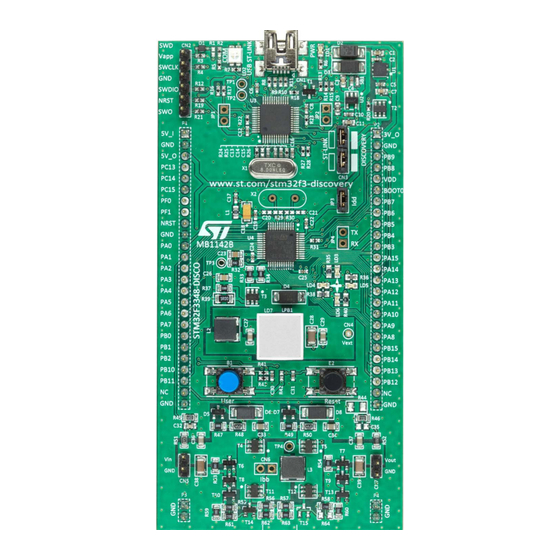
The 32F3348DISCOVERY Discovery kit (order code STM32F3348-DISCO) helps the user
discover the full range of features of the STM32F334 line and develop applications. It is
based on STM32F334C8T6 and includes ST-LINK/V2-1 embedded debug tool interface,
high-brightness LED dimming with buck converter, buck-boost converter, LEDs, and
push-buttons.
The board comes with a comprehensive STM32 software HAL library with various packaged
software examples.
Figure 1. STM32F334 Discovery board
Picture is not contractual.
June 2024
UM1735 Rev 3
1/34
www.st.com
1
Advertisement
Table of Contents

Related Manuals for ST STM32F334C8


Summary of Contents for ST STM32F334C8
-
Page 1: Figure 1. Stm32F334 Discovery Board
The 32F3348DISCOVERY Discovery kit (order code STM32F3348-DISCO) helps the user discover the full range of features of the STM32F334 line and develop applications. It is based on STM32F334C8T6 and includes ST-LINK/V2-1 embedded debug tool interface, high-brightness LED dimming with buck converter, buck-boost converter, LEDs, and push-buttons. -
Page 2: Table Of Contents
Embedded ST-LINK/V2-1 ........14... - Page 3 UM1735 Contents 32F3348DISCOVERY Discovery kit information ....28 Product marking ..........28 32F3348DISCOVERY product history .
- Page 4 List of tables UM1735 List of tables Table 1. List of available products ........... 7 Table 2.
- Page 5 ST-LINK/V2-1 connections ........
-
Page 6: Features
• External application power supply: 3 and 5 V • On-board ST-LINK/V2-1 debugger/programmer with USB re-enumeration capability: mass storage, Virtual COM port, and debug port • Comprehensive free software libraries and examples available with the STM32CubeF3 MCU Package •... -
Page 7: Ordering Information
UM1735 Ordering information Ordering information To order the 32F3348DISCOVERY Discovery kit, refer to Table 1. Additional information is available from the datasheet and reference manual of the target STM32. Table 1. List of available products Order code Board reference Target STM32 STM32F3348-DISCO MB1142 STM32F334C8T6... -
Page 8: Development Environment
The latest versions of the demonstration source code and associated documentation can be downloaded from www.st.com. a. macOS is a trademark of Apple Inc., registered in the U.S. and other countries and regions. -
Page 9: Conventions
UM1735 Conventions Conventions Table 3 defines some conventions used in the present document. Table 3. ON/OFF conventions Convention Definition Jumper JPx ON Jumper fitted Jumper JPx OFF Jumper not fitted Jumper JPx [1-2] Jumper fitted between pin 1 and pin 2 Solder bridge SBx ON SBx connections closed by 0 Ω... -
Page 10: Hardware Layout
The STM32F334 Discovery board is designed around the STM32F334C8T6 microcontroller in a 48-pin LQFP package. Figure 2 illustrates the connections between the STM32F334C8T6 and its peripherals (ST-LINK/V2-1, high-brightness LED dimming with a buck converter, buck-boost converter, LEDs, and push-buttons). Figure 3 Figure 4 help you to locate these features on the STM32F334 Discovery board. -
Page 11: Figure 3. Top Layout
UM1735 Hardware layout Figure 3. Top layout ST-LINK/V2-1 USB ST-LINK USB ST-LINK USB ST LINK PWR LED (LD1) COM LED (LD2) SWD connector (CN2) Reserved (JP1) 3 V power supply output 5 V power supply input ST-LINK/DISCOVERY 5 V power supply output... -
Page 12: Figure 4. Bottom Layout
Hardware layout UM1735 Figure 4. Bottom layout Reserved (SB2, SB4, SB7, and SB9) STM-RST (SB6) Default (SB3, SB5, SB8, and SB10) NRST MCO (SB12) (SB11) VCP RX, TX X2 crystal (SB14 and SB16) (SB13 and SB15) SWO (SB17) Vext (SB18) (SB19) B2-RESET (SB20) -
Page 13: Figure 5. Stm32F334 Discovery Board Mechanical Drawing
UM1735 Hardware layout Figure 5. STM32F334 Discovery board mechanical drawing UM1735 Rev 3 13/34... -
Page 14: Embedded St-Link/V2-1
Features not supported on ST-LINK/V2-1: – SWIM interface – Minimum supported application voltage limited to 3 V There are two different ways to use ST-LINK/V2-1, depending on the jumper states (refer to Table • Program/debug the MCU on board. Refer to Section 5.1.4. -
Page 15: St-Link/V2-1 Firmware Upgrade
ST-LINK/V2-1 firmware upgrade ST-LINK/V2-1 embeds a firmware upgrade mechanism for the in-place upgrade through the USB port. The firmware might evolve during the lifetime of the ST-LINK/V2-1 product (for example new functionality, bug fixes, and support for new microcontroller families). Visit www.st.com... -
Page 16: Using St-Link/V2-1 To Program/Debug The Stm32F334 Mcu
Hardware layout UM1735 5.1.4 Using ST-LINK/V2-1 to program/debug the STM32F334 MCU on board To program the STM32F334 MCU on board, plug in the two jumpers on CN3, as shown in Figure 7, but do not use the CN2 connector as that might disturb communication with the STM32F334C8T6 of the STM32F334 Discovery board. -
Page 17: Using St-Link/V2-1 To Program/Debug An External Stm32 Application
Hardware layout 5.1.5 Using ST-LINK/V2-1 to program/debug an external STM32 application It is very easy to use ST-LINK/V2-1 to program an STM32 microcontroller on an external application. Simply remove the two jumpers from CN3 as shown in Figure 8 and connect... -
Page 18: Power Supply And Power Selection
Hardware layout UM1735 Figure 8. ST-LINK/V2-1 connections Power supply and power selection The power supply is provided either by the host PC through the USB cable, or by an external 5 V power supply. The STM32F334 Discovery board requires 500 mA from the host PC but around 300 mA is needed for its demo, 100 mA for an extension board, and a safety margin of 100 mA. -
Page 19: Power Supply Input From The Usb Connector
All parts of the STM32F334 Discovery board and extension board can be powered from the ST-LINK/V2-1 USB connector CN1 (U5V or VBUS). Note that only the ST-LINK/V2-1 part is power supplied before the USB enumeration as the host PC only provides 100 mA to the board at that time. -
Page 20: Leds
• LD2 COM: The LD2 default status is red. LD2 turns to green to indicate that the communications are in progress between the PC and ST-LINK/V2-1. • User LD3: The red LED is a user LED connected to the I/O PB6 of the STM32F334C8T6. -
Page 21: Buck-Boost Converter
For more details concerning the buck-boost converter, refer to the application note Buck-boost converter using the STM32F334 Discovery kit (AN4449). • The STM32Cube library is available from www.st.com/en/product/32f3348discovery. Note: If a buck-boost converter is used, then the LED buck converter cannot be enabled. -
Page 22: Usart Configuration
USART configuration The USART2 interface available on PB3 and PB4 of the STM32F334C8T6 can be connected to the ST-LINK/V2-1 MCU to use the Virtual COM port function. By default the USART2 communication between the target STM32F334C8T6 and ST-LINK/V2-1 MCU is not enabled. -
Page 23: Solder Bridges
SB22 (L3) Use CN6 for Current measurement. ST-LINK/V2-1 module is powered SB1 (ST-LINK/V2-1 PWR) ST-LINK/V2-1 module is not powered Default position. SB19 (LED) Use it connecting 2 wires for Current measurement. T_NRST signal from connector CN2 and STM32F103CBT6, is connected to... -
Page 24: Extension Connectors
Hardware layout UM1735 5.12 Extension connectors The male headers P1 and P2 can connect the STM32F334 Discovery board to a standard prototyping/wrapping board. STM32F334C8T6 GPIOs are available on these connectors. An oscilloscope, logical analyzer, or voltmeter can also probe P1 and P2. Table 7. - Page 25 UM1735 Hardware layout Table 7. Extension connectors (continued) MCU pin Board function PA10 PA11 PA12 PA13 PA14 PA15 UM1735 Rev 3 25/34...
- Page 26 Hardware layout UM1735 Table 7. Extension connectors (continued) MCU pin Board function PB10 PB11 PB12 PB13 PB14 PB15 PC13 PC14 PC15 26/34 UM1735 Rev 3...
- Page 27 UM1735 Hardware layout Table 7. Extension connectors (continued) MCU pin Board function VBAT VDDA VSSA 1. Signals available depending on SBx value. Refer to Table 6: Solder bridges or electrical schematics. UM1735 Rev 3 27/34...
-
Page 28: 32F3348Discovery Discovery Kit Information
Parts marked as "ES" or "E" are not yet qualified and therefore not approved for use in production. ST is not responsible for any consequences resulting from such use. In no event will ST be liable for the customer using any of these engineering samples in production. -
Page 29: 32F3348Discovery Product History
UM1735 32F3348DISCOVERY Discovery kit information 32F3348DISCOVERY product history Table 8. Product history Order Product Product change Product details Product limitations code identification description MCU: – STM32F334C8T6 revision “Z” – Initial revision MCU errata sheet: – This product – STM32F334x4/x6/x8 identification was 32F3348DISCO/ No limitation Rev Z device limitations... -
Page 30: Board Revision History
32F3348DISCOVERY Discovery kit information UM1735 Board revision history Table 9. Board revision history Board variant and Board change Board reference Board limitations revision description F334-B01 Initial revision No limitation SB14 and SB16 fitted ON F334-B02 No limitation for VCP Several components changed due to obsolescence: –... -
Page 31: Federal Communications Commission (Fcc) And Ised Canada Compliance Statements
UM1735 Federal Communications Commission (FCC) and ISED Canada Compliance Statements Federal Communications Commission (FCC) and ISED Canada Compliance Statements FCC Compliance Statement 7.1.1 Part 15.19 This device complies with Part 15 of the FCC Rules. Operation is subject to the following two conditions: (1) this device may not cause harmful interference, and (2) this device must accept any interference received, including interference that may cause undesired operation. -
Page 32: Ised Compliance Statement
Federal Communications Commission (FCC) and ISED Canada Compliance Statements UM1735 ISED Compliance Statement This device complies with FCC and ISED Canada RF radiation exposure limits set forth for general population for mobile application (uncontrolled exposure). This device must not be collocated or operating in conjunction with any other antenna or transmitter. -
Page 33: Revision History
UM1735 Revision history Revision history Table 10. Document revision history Date Revision Changes 19-Jun-2014 Initial release Change of STM32F3x4 to STM32F334 in Introduction. mbed-enabled logo added on the cover page. Added mbed-enabled in Section 3: Features. Added Section 2.1: Product marking. - Page 34 ST products and/or to this document at any time without notice. Purchasers should obtain the latest relevant information on ST products before placing orders. ST products are sold pursuant to ST’s terms and conditions of sale in place at the time of order acknowledgment.
Need help?
Do you have a question about the STM32F334C8 and is the answer not in the manual?
Questions and answers