Table of Contents
Advertisement
Advertisement
Table of Contents

Related Manuals for Assa Abloy PTI AP1


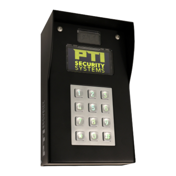
Summary of Contents for Assa Abloy PTI AP1
- Page 1 KEYPAD USER MANUAL 2024 VER 032624...
-
Page 2: Table Of Contents
KEYPAD User Manual TABLE OF CONTENTS Introduction ........................3 Specifications ........................4 Opening & Connections .................... 5-7 Power ............................8 Applications & Mounting ..................9-13 Switches ..........................14 Display ........................15-16 Configuration Menu ....................17-19 Status ..........................20 Change Log ........................21 Warranty ........................... 22 NOTE: This equipment has been tested and found to comply with the limits for a Class A digital device, pursuant to part 15 of the FCC Rules. -
Page 3: Introduction
KEYPAD User Manual Sales: +1.800.523.9504 Support: +1.866.240.7602 Web: ptisecurity.com Rev C – March 2024 INTRODUCTION The AP1 (Access Point 1) is a PTI RS485 peripheral used for access control at a gate or door. This document is intended to provide a high level overview of how to operate the the unit. -
Page 4: Specifications
KEYPAD USER MANUAL | SPECIFICATIONS Electrical Specifications: Input Voltage: 12 to 48V DC supplied by a Class 2 current limited source Power Consumption: < 2.5W estimate (does not include keypad heater) Communication: 2-wire RS485 at 9600 baud Inputs: 2 with optional supervision using 1K resistors in series, parallel or both. -
Page 5: Opening & Connections
KEYPAD USER MANUAL | OPENING & CONNECTIONS How to Open and Close the AP1 The AP1 is held closed with two captive screws at the top and a hinge at the bottom. Use a TORX T15 bit to loosen the two captive screws and the top front of the AP1. - Page 6 KEYPAD USER MANUAL | OPENING & CONNECTIONS Board Connections and LEDs Connectors Earth Ground Connect to a DC power source of 12 to 48 volts. AC input is NOT supported. A Class 2 current limit supply must be used. D+ / ‘A’ GND / Shield Connection D- / ‘B’...
- Page 7 KEYPAD USER MANUAL | OPENING & CONNECTIONS Relay 1 / Relay 2 NO – Normally Open COM – Common NC – Normally Closed Relay 1 controls the door strike, mag lock or gate trigger. Connection between the NO and COM contacts is made when active.
-
Page 8: Power
KEYPAD USER MANUAL | POWER LEDs Power Supplies The red and green LEDs indicate the status of the internal 5V and 12V power supplies. Failure of these LEDs to light when power is supplied to the AP1 would indicate a fault or failure condition. Red LED5 indicates the status or the isolated RS485 power supply. -
Page 9: Applications & Mounting
KEYPAD USER MANUAL Typical Applications Before installing the keypad, determine where and how the device will be installed, since the mounting location is determined by how the device will be used. For drive up access, install the device where it can be reached from the vehicle’s driver door. If the keypad is being used for walk up access, install it where it can be accessed by a person on foot. - Page 10 KEYPAD USER MANUAL When positioning the keypad for drive up accessibility, it must be mounted with easy reach of the driver of an automobile or light truck when considering the touchpad being used for access. Most of these locations use gooseneck stands or keypad bollards with cap on an island between the entry and exit gates (or to the left side of the gate if a single gate is used).
- Page 11 KEYPAD USER MANUAL filled bollards to prevent vehicles from damaging the keypad. • There are several different styles of gooseneck stands available. Single Bollard • A bollard is an attractive and functional stand for keypads. It helps protect the keypad from vehicle damage.
- Page 12 KEYPAD USER MANUAL | APPLICATIONS Single Keypad Gate Access In 1 Gate Contact (optional) In this application a single keypad is used to control ingress into the facility. A loop detector In 2 Vehicle Loop is used for egress connected to Input 2. Relay 1 is Detector used to trigger the gate.
- Page 13 KEYPAD USER MANUAL | APPLICATIONS Door Control and Monitoring Door In 1 Contact This application is used to control and monitor In 2 Req to Exit Button a door. Events, which can trigger alarms, will be or Motion Sensor created when the door is forced open or held Door Strike or open past the specified limit.
-
Page 14: Switches
KEYPAD USER MANUAL | SWITCHES Input Switch Supervision The AP1 has the capability to monitor the two inputs for tampering. This is accomplished by using supervised switches. Supervised switches incorporate 1K ohm resistors securely located inside the switch housing. Supervision Type Diagram Description An unsupervised configuration is shown to the left. -
Page 15: Display
KEYPAD USER MANUAL | DISPLAY AP1 Operation and the Graphic Display: The AP1 incorporates a display capable of rendering mono chrome graphics images. This capability has been leveraged in the firmware while still maintaining the text only capabilities of the VP and APEX. When a credential is entered at the AP1 a request is made of the controller. - Page 16 KEYPAD USER MANUAL | DISPLAY This is the response sent to the VP class keypads with 2 x 16-character displays. All responses will be text and specified in Storlogix. Note that the AP1 has no idea how 2 x 16 Text Response the controller responded and therefore the controller is responsible for activating the relay.
-
Page 17: Configuration Menu
KEYPAD USER MANUAL | CONFIGURATION MENU Configuration: The configuration menu is accessible by pressing the ‘*’ , ‘0’ and ‘#’ keys simultaneously. A ‘>’ prompt will appear. Enter the password to enter configuration mode. The default password is “8898”. After entering the correct password an “ok >” prompt will appear. If an incorrect password or command is entered a “? >”... - Page 18 KEYPAD USER MANUAL | CONFIGURATION MENU Used to change the password to enter configuration mode. Note: Record the new password or you will not be able to enter configuration mode. (Note that we currently don’t have a means to reset to the default password. Need a solution for this should the password be unknown.) Displays the help screen for command group 10 Beeper and Display Toggles beep with key press...
- Page 19 KEYPAD USER MANUAL | CONFIGURATION MENU Cycles through the Relay 2 functions: • Alarm Out • General Purpose (only activated by controller) • Different Hold time. Activated when Relay 1 is activated but for a different length of time. Used for controlling door holders. •...
-
Page 20: Status
KEYPAD USER MANUAL | STATUS AP1 Properties and Status During normal operation, press the ‘*’ key followed by the ‘#’ key. The AP1 will display the electronic part number, serial number, manufacturing date and firmware revision. Pressing the ‘#’ key a second time will display a status screen which will show the following: •... -
Page 21: Change Log
KEYPAD USER MANUAL | CHANGE LOG Revision History: 1 – Initial release 2 – Added the operation and graphic display section 3 - Mounting options added; regulatory certificates Page - 21... -
Page 22: Warranty
KEYPAD USER MANUAL | WARRANTY & DISCLAIMERS This warranty is exclusive and in lieu of all other warranties, expressed or implied, including but not limited to the implied warranties of merchantability and fitness for a particular purpose. PTI Security Systems will not be liable to anyone for any consequential or incidental damages for breach of this warranty or any other warranties. - Page 23 With PTI Security Systems, operators can easily customize all of their facility’s access areas, review site activity, and monitor zones and alarms from one cloud- based account. Create a world-class operation with the most advanced enterprise access control solution from the trusted industry leader with over 40 years of experience.
Need help?
Do you have a question about the PTI AP1 and is the answer not in the manual?
Questions and answers