Assa Abloy Securitron DK-26 Manual
Assa digital keypad manual dk-26
Hide thumbs
Also See for Securitron DK-26:
- Installation and operating instructions manual (23 pages) ,
- Manual (12 pages) ,
- Installation and operating instructions manual (23 pages)
Table of Contents
Advertisement
PN# 500-16900
Rev. A.2, 10/03
TABLE OF CONTENTS AND GUIDE TO THIS MANUAL
The DK-26 is a powerful and versatile product with many features and modes of operation. In
most applications you will use only some of these features so this table of contents includes a
description of the type of application that applies to each different section. By studying it first,
you can save considerable time by skipping over those parts of the manual that don't apply to
your application.
SECTION 1. DESCRIPTION --------------------------------------------------------------------Page 1
SECTION 2. PHYSICAL INSTALLATION ---------------------------------------------------Page 1
SECTION 3. WIRING------------------------------------------------------------------------------Page 3
SECTION 3.1 POWER SELECTION ----------------------------------------------------------Page 3
This section explains the power that must be used and gives you power consumption
figures.
SECTION 3.3 POWER AND ELECTRIC LOCK WIRING--------------------------------Page 3
This section introduces the different basic wiring schemes generally required for electric
strike control (no exit switch needed). The three sections below provide separate drawings
and descriptions depending on your power source and on the power required by the lock.
SECTION 3.3.1 AC LOCK WITH AC POWER ---------------------------------------------Page 3
SECTION 3.3.2 DC LOCK WITH AC POWER ---------------------------------------------Page 5
SECTION 3.3.3 DC LOCK WITH DC POWER ---------------------------------------------Page 6
The "F" terminal is mainly used for convenient connection of fire alarm contacts which will
release a fail safe lock in the event of activation of the fire alarm.
SECTION 3.5 ADDING OTHER LOCK CONTROL SWITCHES-----------------------Page 7
This section and drawing show proper connection for an external switch such as from
Securitron's Lock Control Panel.
SECTION 3.6 THE REX FUNCTION ----------------------------------------------------------Page 8
When you are using a magnetic lock or solenoid bolt, you often require a separate switch to
allow egress. This switch can be connected to the CPU board to provide timed egress in
different ways. This section fully covers this requirement.
SECTION 4. PROGRAMMING -----------------------------------------------------------------Page 10
SECTION 4.1 FIXED PROGRAMMING ------------------------------------------------------Page 10
Fixed programming is for lower security applications when the code is not expected to need
regular changing by the user. The "Hard" code is used for this requirement.
© Copyright, 2003, all rights reserved • Securitron Magnalock Corp., 550 Vista Blvd., Sparks NV 89434, USA
Tel: (775) 355-5625 • (800) MAGLOCK • Fax: (775) 355-5636 • Website: www.securitron.com
An ASSA ABLOY Group company
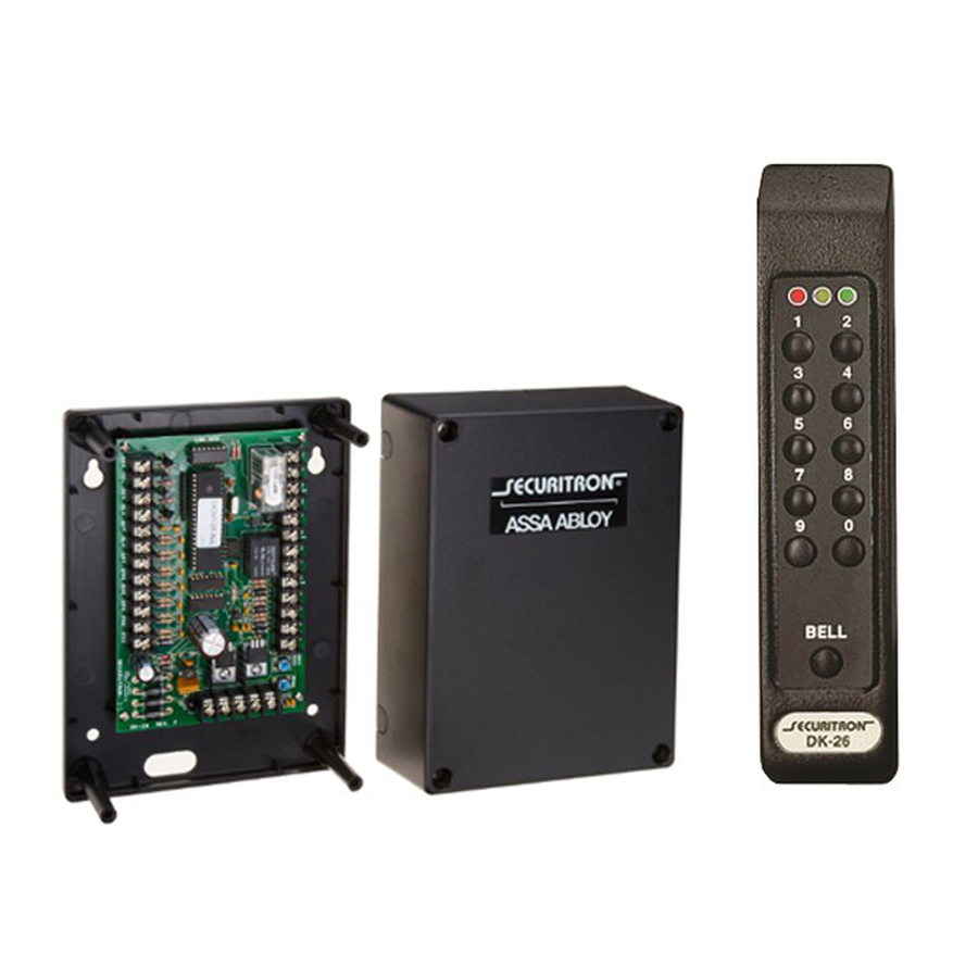
SECURITRON MODEL DK-26 DIGITAL KEYPAD
Advertisement
Table of Contents

Related Manuals for Assa Abloy Securitron DK-26


Summary of Contents for Assa Abloy Securitron DK-26
-
Page 1: Table Of Contents
TABLE OF CONTENTS AND GUIDE TO THIS MANUAL The DK-26 is a powerful and versatile product with many features and modes of operation. In most applications you will use only some of these features so this table of contents includes a description of the type of application that applies to each different section. - Page 2 SECTION 4.6 SETTING THE TIME RANGE AND TOGGLE MODE -----------------Page 16 As factory set, the DK-26 will release the lock for five seconds. This section explains how to change that setting and enable “toggle” mode where successive code entries will energize and then deenergize the lock control relay.
- Page 3 The DK-26 can shunt an active alarm point for authorized entry. SECTION 7.4 ANTI-TAILGATING -------------------------------------------------------------Page 20 With this feature, you can abort the DK-26’s timer once the door is opened to make sure only one person enters. SECTION 7.5 WIRING WITH TOUCH SENSE BAR AND MAGNALOCK ----------Page 20 This section provides a drawing for a popular combination of Securitron products.
-
Page 4: Section 1. Description
Phillips standard screw may be used. After this, peel the backing of the enclosed Securitron DK-26 label and affix it to the bottom of the keypad covering the head of the screw. This not only improves the appearance of the keypad but helps foil casual vandalism. Note finally that a blank rectangular label has also been furnished. - Page 5 TOP OF KEYPAD DRILL 1/8" (3MM) HOLE (2) DRILL 3/8" (10MM) HOLE FOR CABLE CABLE (3) SECURE BOTTOM WITH SECOND SCREW. COVER SCREW HEAD WITH "DK-26" LABEL. DRILL 1/8" (3MM) HOLE NOTE: CHOOSE PHILIPS OR SPANNER (TAMPER) HEAD SCREW Page-2...
-
Page 6: Section 3. Wiring
3. WIRING 3.1 POWER SELECTION The DK-26 operates on 12 to 24 volts AC or DC. Nearly all electric locks operate on voltage within this range, so the power supply you would normally utilize to operate the electric lock will also operate the DK-26. - Page 7 Rev. A.2, 10/03 12/24 AC POWER FREE TERMINAL 12/24 DC NEGATIVE 12/24 DC POWER + DC TERMINALS MAY ALSO BE USED AS OUTPUT TO POWER PRGM DC LOCK, IF AC CODE POWER IS SUPPLIED FIG. 2: OVERVIEW OF CPU BOARD KEYPAD CABLE HARD SRC REX UCD HCD NCX...
-
Page 8: Section 3.3.2 Dc Lock With Ac Power
For convenience and economy, most DC electric locks can be operated from an AC transformer when the DK-26 is used. Select a transformer of the same voltage as the lock (12 or 24). The CPU board converts the input AC to DC to operate the lock. Make sure the capacity of the transformer is large enough to operate both the DK-26 and the lock and that the transformer is UL listed under the UL 294 standard (to maintain the DK-26 UL listed status). - Page 9 Select a power supply of the same voltage as the lock (12 or 24). Make sure the capacity of the supply is large enough to operate both the DK-26 and the lock. The DK-26 does not require regulated power but certain specialized electric locks do, so follow the rule of matching the power supply to the requirements of the lock.
-
Page 10: Section 3.4 Use Of The "F" Terminal
AC IN terminal and F. See the drawing to the right. 3.5 ADDING OTHER LOCK CONTROL SWITCHES The drawings in Section 3.3 are valid for simple installations where the DK-26 is the only control device that can release the electric lock. Often, however, additional control devices are called for. -
Page 11: Section 3.6 The Rex Function
DK-26's timer. The result is the same as if the DK-26 was used from the outside of the door. The REX terminal is activated by being connected to the SRC (voltage source) terminal. It will also activate if +12 or +24V is input to the terminal from the DK-26’s external power supply. -
Page 12: Cpu Board
When using exit switches, the possibility must be considered that an electronic failure may occur to the DK-26 and a person will not be able to exit. If the DK-26 controls the only door exiting the area, additional steps should be taken to improve the reliability of exiting so as to avoid trapping someone. -
Page 13: Section 4. Programming
The DK-26 has ten numbered keys and a bell key which is used for several functions. Each of these keys is read separately by the unit, so the DK-26 is a true 11 digit access device. This provides excellent security against a code being guessed. Also, the DK-26 employs non-volatile EEPROM memory so that all programming is retained in a power failure. - Page 14 The DK-26 makes it simple for you to program the unit in this “fixed” way. You will utilize a push button set, single code called the “Hard code”. With power applied to the unit, note that the yellow LED is on steadily.
-
Page 15: Section 4.2 Keypad Changeable Programming
Section for fixed code programming. 4.2 KEYPAD CHANGEABLE PROGRAMMING In this application, two codes are programmed into the DK-26. The first, called the Program code acts as a password which allows changing the User code. It is the User code which is employed regularly to gain access. -
Page 16: Section 4.2.1 Changing The User And Prog. Code From Keypad
Rev. A.2, 10/03 After you’ve completed your entries, test your user and program codes by entering them. The user code should open the door. The program code should cause the yellow LED to flash rapidly (program mode). Exit the program mode by hitting the Bell key. Below we show a step by step summary of programming the two codes. -
Page 17: Section 4.2.2. Adding Multiple User Codes
Press Bell key to terminate program mode or wait 30 seconds The logic behind this procedure is as follows. All programming for the DK-26 starts with putting the unit into program mode (except entering the single Hard code). The unit is put into program mode by either pressing the “Prgm Code”... -
Page 18: Section 4.4 Subset Codes
The DK-26, however, avoids this problem by rejecting any code that is a subset of another code in memory. It signals this rejection by showing the single red (error) flash instead of the two-flash confirmation signal. -
Page 19: Section 4.6 Setting The Time Range And Toggle Mode
30 seconds. Enter a correct User code to test that the changed time is working. The DK-26 will operate in toggle mode if key 9 followed by 00 is entered when the unit is in program mode. In toggle mode operation, the relay will energize when a correct code is entered and deenergize when a correct code is entered a second time. -
Page 20: Section 6 Use Of The Programmable Relay
7-4. 6. USE OF THE PROGRAMMABLE RELAY The DK-26 CPU board includes a second relay whose 5 Amp, SPDT contacts are marked CX, NCX and NOX (see Figure 2). This relay is employed for different functions which are selected by commands sent to the CPU board while the unit is in program mode. -
Page 21: Section 6.3 Anti-Tamper Alarm Function
Rev. A.2, 10/03 6.3 ANTI-TAMPER ALARM FUNCTION A person attempting to guess the code and pressing 16 wrong digits will put the DK-26 into alarm. The keypad's beeper and green LED will operate for 30 seconds during which time the keypad will accept no input. -
Page 22: Section 6.5 Nightlight Function
This means making a switch connection to the CPU board which will cause valid codes to not be accepted. The DK-26 has two terminals marked “HCD” and “UCD” which will respectively disable the Hard code and all User codes. Simply connect the SRC terminal to either of these terminals via an external switch and the respective codes will not function while the switch is closed. -
Page 23: Section 7.3 Alarm System Shunting
7.3 ALARM SYSTEM SHUNTING The DK-26's lock control relay is of the double pole, double throw type. Note that in all the other drawings in this manual, we show only one of the poles being used (C1, NC1 and NO1). The most common use for the second pole (C2, NC2 and NO2) is to shunt out an alarm system, which would be connected to the door when the DK-26 is being utilized. - Page 24 Note that a variation of this wiring scheme could be desired if you are using the second pole of the DK-26’s lock control relay to shunt an alarm system (see Section 7.3). You would then want the Touch Bar to operate the DK-26’s lock control relay in double break fashion so that the alarm system is shunted both for entry and exit.
- Page 25 Rev. A.2, 10/03 Page-22 ® MAGNACARE LIMITED LIFETIME WARRANTY SECURITRON MAGNALOCK CORPORATION warrants that it will replace at customer’s request, at any time for any reason, products manufactured and branded by SECURITRON. SECURITRON will use its best efforts to ship a replacement product by next day air freight at no cost to the customer within 24 hours of SECURITRON’s receipt of the product from customer.
-
Page 26: Appendix A: Command Summary
Rev. A.2, 10/03 Page-i APPENDIX A: COMMAND SUMMARY WITH THE UNIT IN PROGRAM MODE (FAST YELLOW FLASH): 00 followed by 5-7 digits sets Program code 01 followed by 2-7 digits set first User code 02-followed by 2-7 digits sets second User code Additional User codes can be set up to the prefix 59 (total 59 User codes) 70 will sound beeper when door is open (except toggle mode). -
Page 27: Appendix B: Troubleshooting
If the voltage reads very low, the problem may be that a fail safe lock being controlled by the DK-26 is drawing too much current for the power supply. Remove the lock from the circuit. If this restores proper voltage and operation of the DK-26, you'll have to determine if the power supply is undersized or if there is a short circuit in the lock wiring which is pulling down the power supply. - Page 28 Rev. A.2, 10/03 If PolySwitch #1 has tripped, visually inspect the four large diodes on the board to see if a loose wire has fallen on them to create a short circuit. If you do not find such a physical problem that can be easily corrected, the board should be replaced although you should be aware that it can be operated with no problems from a DC power supply connected into the DC input terminals if only PolySwitch #1 has tripped.
- Page 29 Rev. A.2, 10/03 entry will be ignored. Finally note that if terminals SRC and UCD are connected, all User codes will be disabled. If terminals SRC and HCD are connected, the Hard code will be disabled. PROBLEM -- Beeper doesn’t sound while the unit otherwise functions Note that the beeper could have been deliberately silenced by the unit having been sent a special command.
- Page 30 If the problem shows up frequently, it is usually bad power. This particularly occurs when a fail secure lock is operated from the same supply as the DK-26. When the lock is energized, it may draw too much power for the power source.
Need help?
Do you have a question about the Securitron DK-26 and is the answer not in the manual?
Questions and answers