Advertisement
nexTouch
®
Sectional Mortise Lock Touchscreen and Push Button
Installation and Programming Instructions
Retrofitting or modifying this product may impact fire rating, safety features and warranty.
Consult with code specifications to ensure compliance with all codes and ratings.
80-9086-0030-010 04/2024
1-800-810-9473 • www.accentra-assaabloy.com
Copyright © 2020-2024, ASSA ABLOY ACCENTRA™ Access and Egress Hardware Group, Inc. All rights reserved. Re-
production in whole or in part without the express written permission of ASSA ABLOY Access and Egress Hardware
Group, Inc. is prohibited. Patent pending and/or patent www.assaabloydss.com/patents.
Keypad Access
Optional
Multi-Family
Key Module
1/8"
3/32"
Tools Needed
3/4" 1/2"
#3 & #2
Advertisement
Table of Contents

Subscribe to Our Youtube Channel
Related Manuals for Assa Abloy ACCENTRA nexTouch


Summary of Contents for Assa Abloy ACCENTRA nexTouch
- Page 1 Copyright © 2020-2024, ASSA ABLOY ACCENTRA™ Access and Egress Hardware Group, Inc. All rights reserved. Re- production in whole or in part without the express written permission of ASSA ABLOY Access and Egress Hardware Group, Inc. is prohibited. Patent pending and/or patent www.assaabloydss.com/patents.
- Page 2 Determine Handing The hand of a door is determined from the secure side of the door. The term “secure” means the side from which you initially unlock and enter. Deadbolt Latchbolt Beveled edge must face strike. (See step 1 to reverse latchbolt.) RED Locking Slide should face the...
- Page 3 Hand Latchbolt & Hubs (If Necessary) Insert flat head screwdriver to pry latch head up. Rotate latch head to correct orientation. Slide Locking PUSH away from square hole to create gap. Check for free movement of locking slide. Continue to rotate locking slide from other side until “set”...
- Page 4 Copyright © 2015, 2024, ASSA ABLOY ACCENTRA™ Access and Egress Hardware Group, Inc. All rights reserved. Reproduction in Rev D whole or in part without the express written permission of ASSA ABLOY Access and Egress Hardware Group, Inc. is prohibited. Drill thru holes 1/2 way...
- Page 5 Prepare Frame & Install Strike #12-24x1" Flat Head Combo Screw Frame This prep is standard with or without deadbolt. Optional Strike Box Use #3 Philips head screwdriver 80-9086-0030-010 04/2024...
- Page 6 Install Mortise Lock #12-24x1" Flat Head Combo Screw Inside of Door Mortise Lock Cable Hole Do not tighten screws until Step 10. Use #3 Philips head screwdriver Make sure mortise pocket is free from debris. 80-9086-0030-010 04/2024...
-
Page 7: Test Operation
Install Key Cylinder (if applicable) For Cylinder Option ONLY Outside of Door It may be necessary to loosen the cylinder set screw before installing the cylinder. Use #2 Philips head screwdriver Outside of Door First, tighten HAND TIGHTEN. cylinder until snug Do not use powered against door with screwdriver. - Page 8 Install Rose Trim - all types #8-32x1" Pan Head Screw Adjusting for 1-3/4" to 2-1/4" Door (if necessary) with Thread Locker (For 1-3/4" Door) Use screw pack for thicker door at this step. Use appropriate fasterner lengths to ensure proper installation. Outside of Door If provided Inside of Door...
- Page 9 Prepare Levers Loosen Inside Spindle 1/2 to 1 turn until Correct Orientation. Correct Inside Lever Orientation Inside Spindle Outside Lever Install Levers Pushing levers together, use hex wrench to tighten set screw securely against spindle. Outside of Door 80-9086-0030-010 04/2024...
- Page 10 Install Thumbturn (if applicable) For Deadbolt Option ONLY #6x3/8" Oval Head Screw Inside of Door Use #2 Philips head screwdriver Test Operation Deadbolt retracts and extends by thumbturn and key. Once extended, it will also retract by lever. Latchbolt retracts and extends by levers and key.
- Page 11 Install Armor Front #8-32x1/4" Flat Head Screw Outside of Door Logo will be at top and visible when installed. Use #2 Philips head screwdriver Tighten lockbody screws before installation of front. Do not bow front of lock case by overtightening. Test Operation Again 80-9086-0030-010 04/2024...
- Page 12 Install Keypad Inside of Door 80-9086-0030-010 04/2024...
- Page 13 Install Inside Mounting Plate #8-32x3/4" Pan Head Screw with Washer (For 1-3/4" Door) 3/32" Hex Wrench Choose fasteners appropriate for your door thickness. Inside of Door Use #2 Philips head screwdriver 80-9086-0030-010 04/2024...
- Page 14 Attach Cables to Inside Lock Inside of Door Cables must be clear of all fastener holes. 80-9086-0030-010 04/2024...
- Page 15 Install Inside Lock #8-32x3/8" Pan Head Screw (Black) Inside of Door Use #2 Philips head screwdriver 80-9086-0030-010 04/2024...
-
Page 16: Installation Options
ONLY. Creation and use of User PIN codes are disabled. Install Batteries & Cover Ensure that optional Multi-Family Key Module is installed BEFORE batteries if necessary. See Installation Options. ® Congratulations, you’ve installed the ACCENTRA nexTouch Sectional Mortise Lock! 80-9086-0030-010 04/2024... -
Page 17: Programming Instructions
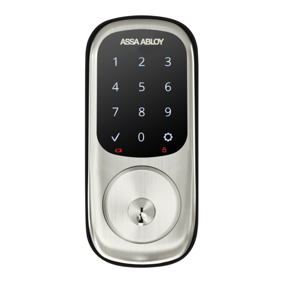
Programming Instructions Lock Activation (Push Button) Lock Activation (Touchscreen) Press any key Press ACCENTRA logo Touch keypad with whole hand Press check key Unlock Indicator (Touchscreen) Low Battery Indicator Lockout Mode Indicator (Touchscreen) (Touchscreen) 9 Volt Battery Override Terminal Keypad Indicator Light Speaker Privacy Button... - Page 18 Creating Master PIN Code Creating a Master PIN Code must be performed upon installation or after resetting the lock to factory default. Programming and use of lock is not possible until this step has been successfully completed. “Register Master Code. Press the gear Activate Lock key to continue.”...
- Page 19 Creating User PIN Codes Master PIN code must be created first. The Multi-Family Key module enables access with physical (cards and fobs) and mobile credentials ONLY. Creation and use of User PIN codes are disabled. Enter Master PIN Code Activate Lock Press “Menu Mode, enter number.”...
- Page 20 Creating User PIN Codes con’t Enter 4-8 digit PIN code followed by “Registered. Press the check key to complete. Press the gear key to continue.” To end programming: Adding more User Codes: Press Press Enter 4-8 digit PIN code Press “Completed.”...
- Page 21 Locking & Unlocking Door with Registered Master or User PIN Code The Multi-Family Key module enables access with physical (cards and fobs) and mobile credentials ONLY. Creation and use of User PIN codes are disabled. Master PIN code is only used for programming and configuring lock with ACCENTRA Multi-Family configuration app and will not unlock door.
- Page 22 Resetting Lock to Factory Default Reset Button #2 Philips Head Hex Wrench Screwdriver Interior Escutcheon When lock is reset to factory defaults, all PIN codes, including the Master PIN code, are deleted and all programming features are reset to original default settings (see Factory Settings). IMPORTANT: The Reset Button is located on Interior Escutcheon.
- Page 23 Definitions All Code Lockout Mode: This feature is enabled by the Master PIN code. When enabled, it restricts all user (except Master) PIN code access. When attempting to enter a code while unit is in Lockout, there will be an audible lock response. The touchscreen keypad will display a RED locked padlock.
-
Page 24: Feature Programming Through Menu Mode Using Master Pin Code
Feature Programming Through Menu Mode Using Master PIN code* 1. Activate the lock. 2. Enter 4-8 digit Master PIN code* followed Master PIN Code Setting key. Register User or Passage Codes Continue User Code Complete Lock Response: “Menu mode, enter number (enter digit Passage Code Continue... -
Page 25: Programming Troubleshooting
Programming Troubleshooting Symptom Suggested Action Lock does not respond. Touchscreen models become active by pressing ACCENTRA logo or There are no lights or chimes and there is no key or by touching keypad with whole hand. mechanical sound indicating latchbolt •... -
Page 26: Factory Settings
Factory Settings Settings Factory Setting Master PIN Code Creation required* All Code Lockout Mode Disabled Automatic Relock Disabled Escape Return Mode Disabled Inside Indicator Light Enabled Language English** One Touch Locking Enabled Privacy Mode Disabled Shutdown Time 60 Seconds Wrong Code Entry Limit 5 Times Volume Setting High... -
Page 27: Warnings And Notices
Warnings and Notices WARNING: Changes or modifications to this device not expressly approved by ASSA ABLOY Avertissment : Les changements ou modifications apportés à ce dispositif sans l’approbation ACCENTRA could void the user’s authority to operate the equipment.. expresse d’ASSA ABLOY ACCENTRA peuvent annuler le droit de l’utilisateur à utiliser l’équipement. - Page 28 Copyright © 2020-2024, ASSA ABLOY ACCENTRA™ Access and Egress Hardware Group, Inc. All rights reserved. Reproduction in whole or in part without the express written permission of ASSA ABLOY Access and Egress Hardware Group, Inc. is prohibited. Patent pending and/or patent www.assaabloydss.com/patents.
Need help?
Do you have a question about the ACCENTRA nexTouch and is the answer not in the manual?
Questions and answers