Advertisement
Quick Links
TC-1514-IP
Rev. D, July 2023
http://www.commscope.com
About this manual
This manual describes the basic installation steps of the Compact Closure 150. The document starts with providing an
overview of the tools required to perform the installation. Also warnings and cautions are indicated, which should be
observed before starting the product installation.
Installation steps in this document are limited to: closure preparation, organizer preparation, feeder cable preparation
and installation, storing feeder fibers, closing the closure and mounting the closure. For the installation steps required
for the branch application, refer to TC-1514-IP-BR: CC 150 Branch application. For the installation steps required for the
splice application, refer to TC-1514-IP-SP: CC 150 Splice application. For the installation steps required for the patch
application, refer to TC-1514-IP-PA: CC 150 Patch application.
Images in this manual are for reference only and are subject to change.
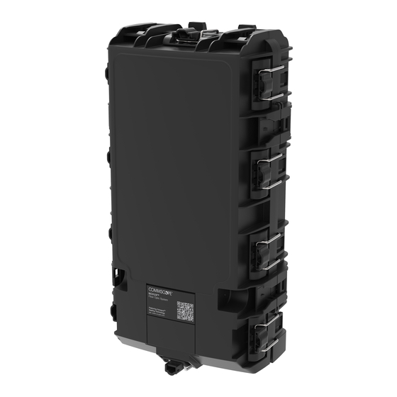
General product information
Dimensions
(7.28 IN)
Cable diameter range
Position
Feeder cable
Branch cable
Single drops
Dual drops
NOVUX™ Fiber Optic System
CC 150 Basic Instructions
18,5 cm
≤18
≤18
≤ 8 (flat cable: 8 x 4,5)
≤ 6,2
© 2023 CommScope, Inc. All Rights Reserved
Installation Instructions
11,5 cm
(4.53 IN)
Cable diameter
mm
page 1 / 28
Inches
≤ 0.71
≤ 0.71
≤ 0.32 (flat cable: 0.32 x 0.18)
≤ 0.25
Advertisement

Subscribe to Our Youtube Channel
Related Manuals for CommScope NOVUX CSC 150 Series


Summary of Contents for CommScope NOVUX CSC 150 Series
- Page 1 ≤ 0.71 Branch cable ≤18 ≤ 0.71 Single drops ≤ 8 (flat cable: 8 x 4,5) ≤ 0.32 (flat cable: 0.32 x 0.18) Dual drops ≤ 6,2 ≤ 0.25 page 1 / 28 © 2023 CommScope, Inc. All Rights Reserved...
- Page 2 R ear side Front side Loop storage basket Subunit transition zones Feeder/ Branch Cable retention Drop Cable retention Patch area or drop feed through (depending on application) Pocket Splice trays Tower page 2 / 28 © 2023 CommScope, Inc. All Rights Reserved...
-
Page 3: Warnings And Cautions
• Fiber optic cables may be damaged if bent or curved to a radius that is less than the recommended minimum bend radius. Always observe the recommended bend radius limit when installing fiber optic cables, subunits and patch cords. page 3 / 28 © 2023 CommScope, Inc. All Rights Reserved... -
Page 4: Kit Contents
Kits and accessories are stored on the top layer. The essential parts under which the Octopus™gel blocks and the yellow snaps, are stored in the side compartment. The closure with organizer is stored under the accessory shelf. page 4 / 28 © 2023 CommScope, Inc. All Rights Reserved... - Page 5 Remove the hinge lock Remove the lock of the hinge in the base. Use a screw driver to push the snap hook backwards. Then slide the lock downwards to remove it. page 5 / 28 © 2023 CommScope, Inc. All Rights Reserved...
- Page 6 Assemble the cover and base by sliding the cover hinges into the cavities within the base. The hinges are properly seated in the base if a clicking sound is noticed. Rotate the cover towards the base and close the cover. page 6 / 28 © 2023 CommScope, Inc. All Rights Reserved...
- Page 7 If the hinges are installed in the top position, the cover cannot be secured in open position. To access the inside of the closure, the cover should be detached. page 7 / 28 © 2023 CommScope, Inc. All Rights Reserved...
- Page 8 Slide the snap downwards while keeping it in place. Verify the snap is correctly installed: the middle part of the snap should be locked underneath the locking feature in the base as shown. page 8 / 28 © 2023 CommScope, Inc. All Rights Reserved...
- Page 9 (in case of a patch application). Lift the snap hooks to release the cover. Hinge the cover upwards. To lock the cover in open position, pull out the blue locking feature. page 9 / 28 © 2023 CommScope, Inc. All Rights Reserved...
- Page 10 2,5 cm / 1 Inch) . Stretch the tape minimum 50% while wrapping the tape around the cable. Make sure the tape is wrapped where the hose clamp will be positioned. page 10 / 28 © 2023 CommScope, Inc. All Rights Reserved...
- Page 11 Tighten the hose clamp with the hex 7 socket wrench. Excess band must be pushed into the slot between the cable and the bracket. Cut off excess rigid strength member at the bracket edge, if applicable. page 11 / 28 © 2023 CommScope, Inc. All Rights Reserved...
- Page 12 Install the open hose clamp into the bracket around the cable and the aramid yarn, while keeping the aramid yarn under tension. Tighten the hose clamp with the hex 7 socket wrench. Excess band must be pushed into the slot between the cable and the bracket. page 12 / 28 © 2023 CommScope, Inc. All Rights Reserved...
- Page 13 Lift up the two port reducers at both sides of the Octopus gel seal with a pair of pliers. ™ Remove the both parts of the respective port. (In total 4 parts for a looped feeder cable.) page 13 / 28 © 2023 CommScope, Inc. All Rights Reserved...
- Page 14 For a cable with diameter less than or equal to 14 mm / 0.55 Inches, install the cable at the left side of the port reducer middle flange, in line with the retention bracket. The middle flange of the port reducer will be pushed to the right side if needed. page 14 / 28 © 2023 CommScope, Inc. All Rights Reserved...
- Page 15 Make loops of the subunits that will not be used and store it in the loop storage basket. Note: The maximum storage capacity depends on the construction and diameters of the subunits in the cable and the number of subunits required to store. page 15 / 28 © 2023 CommScope, Inc. All Rights Reserved...
- Page 16 Route the feeder fiber to the front side via F1 (right side). A line at the front side indicates the stripping point. Mark the subunit at the stripping point and remove the tube per local practice. page 16 / 28 © 2023 CommScope, Inc. All Rights Reserved...
- Page 17 Note: Make sure that the cable tie head ends up on top of the foam bundle. Secure the bundle with two cable ties. Cut off excess cable tie band. page 17 / 28 © 2023 CommScope, Inc. All Rights Reserved...
- Page 18 Make sure all fibers are properly positioned under the lips and avoid bulging of the fiber. Note: The fiber guidance pen can be used to position all the fibers under the lips. page 18 / 28 © 2023 CommScope, Inc. All Rights Reserved...
- Page 19 The fiber guidance pen can be used to position all the fibers under the lips. Re-install organizer Close demarcation cover Slide the lock downwards to unlock the cover. Close the cover. page 19 / 28 © 2023 CommScope, Inc. All Rights Reserved...
- Page 20 There are two positions to store the fiber guidance pen: one on the tower and one on the demarcation cover. Store the fiber guidance pen back to one of these positions. page 20 / 28 © 2023 CommScope, Inc. All Rights Reserved...
- Page 21 First lift the cover slightly up to release the cover from its lock position, then rotate it towards the base. Lift over the spring of the front latch over its center position. There is a little notch to block the spring so it stays in safe position. page 21 / 28 © 2023 CommScope, Inc. All Rights Reserved...
- Page 22 When closing the cover, make sure the metal part of the latch stays at the outside. Close the latches. Start with the rear latch (1). page 22 / 28 © 2023 CommScope, Inc. All Rights Reserved...
- Page 23 Press the snap hooks to the side to release the organizer. Once the bottom part is released, swing the bottom of the organizer frontwards. Now the organizer can slide downwards to release it from the top snap hooks. page 23 / 28 © 2023 CommScope, Inc. All Rights Reserved...
- Page 24 Mount the UMB on a flat surface or onto a pole with 2 screws. Mount the UMB onto a pole with 2 straps Note: Mounting hardware is not a part of the kit. page 24 / 28 © 2023 CommScope, Inc. All Rights Reserved...
- Page 25 The handle can be pushed left or right to unlock the closure. Push the handle to one side. Lift and remove the closure. Note: Verify that the handle is centered again. page 25 / 28 © 2023 CommScope, Inc. All Rights Reserved...
- Page 26 Mounting hardware (such as screws, plugs, washers) should be selected according to intended mounting surface (not included in the kit). 11.2.2 Mounting clips installation Mount the clips on the base on the 4 positions as shown. page 26 / 28 © 2023 CommScope, Inc. All Rights Reserved...
- Page 27 Install the wall plugs first, then position the closure with the mounting clips against the surface. Continue with the washers and the screws to secure the closure onto the surface. page 27 / 28 © 2023 CommScope, Inc. All Rights Reserved...
-
Page 28: Contact Information
This product may be covered by one or more U.S. patents or their foreign equivalents. For patents, see www.cs-pat.com. This document is not intended to modify or supplement any specifications or warranties relating to CommScope products or services.
Need help?
Do you have a question about the NOVUX CSC 150 Series and is the answer not in the manual?
Questions and answers