Table of Contents
Advertisement
Quick Links
TC-1251-2-IP
Rev C, January 2019
www.commscope.com
1.
About this installation instructions
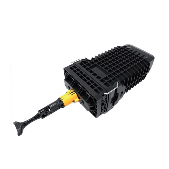
The TENIO fiber enclosure is a modular enclosure that is composed of different building blocks to meet the specific client
needs. This installation instruction provides an overview of the building blocks and their variants and how they fit together.
Environmental conditions in which the enclosure can be used are described in this document as well as product dimensions
and capacity (splice capacity, cable diameter range, and cable types).
In addition this instruction will explain:
- how to prepare the enclosure, feeder cable, and drop cables;
- how to install cables in the enclosure (including use of the CTU);
- how to route fibers to the splice and/or patch trays or to the POC storage area;
- how to install fibers on the trays;
- how to close and properly seal the enclosure;
- how to mount the enclosure with the mounting bracket; and
- how to use the external cable fixation bracket.
This instruction also includes a section describing re-entry to the enclosure after installation for adding a new cable or for
accessing the fiber management system.
2.
Warnings and caution
2.1.
Fiber optic cables may be damaged if bent or curved
to a radius that is less than the recommended minimum bend
radius. Always observe the recommended bend radius limit when
installing fiber optic cables and patch cords.
2.2.
Exposure to laser radiation can seriously damage the
retina of the eye. Do not look into the ends of any optical
fiber. Do not assume the laser power is turned off or
that the fiber is disconnected at the other end.
3.
List of acronyms and abbreviations
POC
Passive Optical Components
CTU
Cable Termination Unit
SKG
Sealing Kit Gel
SLE
SLim Element (tray)
FAS
Fiber Arrangement System
Installation Instructions
TENIO
© 2019 CommScope, Inc. All Rights Reserved
Page 1 of 28
Advertisement
Table of Contents

Related Manuals for CommScope TENIO


Summary of Contents for CommScope TENIO
- Page 1 About this installation instructions The TENIO fiber enclosure is a modular enclosure that is composed of different building blocks to meet the specific client needs. This installation instruction provides an overview of the building blocks and their variants and how they fit together.
-
Page 2: Table Of Contents
(manhole, handhole), ground level (pedestal) and aerial use. The TENIO fiber enclosure is a modular butt splice enclosure fully compatible with G.652.D SM fiber. Fiber and cable technology independent, it can be configured to meet specific requirements in terms of maximum splices, loop storage, optical device storage, and cable diameter. -
Page 3: Sizes And Dimensions
Minimum over length storage per splice side on the tray is 1.2m (47’ ’ ). Tenio-B6 can accommodate up to 12 fiber splice trays (type S12 or A12). Each tray houses 12 fiber splices, for a capacity of maximum 144 fiber splices per closure. -
Page 4: Overview Of The Functionalities (Building Blocks) Of The Enclosure
CABLE SEAL AREA TRIGGER BACK SIDE FIBER GUIDANCE PIN AND WEDGE LOOPSTORAGE (METAL BRACKET) FIBER GUIDING TO TRAYS OR TO FIBER STORAGE TUBE HOLDER CTU HOLDER CABLE SEAL AREA TRIGGER Page 4 of 28 © 2019 CommScope, Inc. All Rights Reserved... -
Page 5: Towers
Splice trays as well as patch trays are available to use in the TENIO. Splice trays are designed to hold SMOUV or ANT splice protectors depending the type. A FAS is used in all splice trays, providing an R40 bend radius. Minimum over length storage per splice side on the tray is 1.2m (47’... -
Page 6: Kit Content
CTU’s and dummies. Following pictures show the kit content of a SKG in the 3 different cases: This kit can contain 1 or 2 gel seal segments. Page 6 of 28 © 2019 CommScope, Inc. All Rights Reserved... -
Page 7: Trays
Measuring tape to measure correct length of Metal band orange tubing and aramid yarn Stripping tools, to prepare cable and fibers Allen key Cleaning tissues to clean cable and fibers Page 7 of 28 © 2019 CommScope, Inc. All Rights Reserved... -
Page 8: Prepare Organizer
When the dome is removed, the cable manage- ment system becomes accessible. When no cables are to be added, base can remain. 8.1.5 End result of dome and base removed. Page 8 of 28 © 2019 CommScope, Inc. All Rights Reserved... -
Page 9: Install Splice Trays
Position the dove tail features in the slots of the 8.2.3 Technical detail of the hinge snapping in the snap POC holder and move the POC to the left side. features on the tower. Page 9 of 28 © 2019 CommScope, Inc. All Rights Reserved... -
Page 10: Prepare Cable
(1.18’ ’ ). To mark this distance, the line on the side of the CTU can be used. Hold the cable jacket flush with the bottom of the CTU and mark the strength member at the height of the line. Page 10 of 28 © 2019 CommScope, Inc. All Rights Reserved... - Page 11 CTU. The cable is left unsecured at this point. Second tighten the screw to secure the strength member. Third tighten the screw to secure the cable jacket. The cable is now fully secured to the CTU. Page 11 of 28 © 2019 CommScope, Inc. All Rights Reserved...
-
Page 12: Ctu-L - Dual Strength Member
(centerline of the metal closest to the CTU. band on the center of the cable). Make sure both ends of the metal band have equal lengths. Page 12 of 28 © 2019 CommScope, Inc. All Rights Reserved... -
Page 13: Ctu-S - Aramid Yarn
Bend the band around the cable making side of the CTU. sure both ends have equal lengths. Page 13 of 28 © 2019 CommScope, Inc. All Rights Reserved... -
Page 14: Install Gel Seal Segments
2 side slots of the cable seal area. The gel can be squeezed slightly together to fit within the protrusions that will keep the side seal segments in place. 9.3.4.5. Cut the excessive aramid yarn as shown. Page 14 of 28 © 2019 CommScope, Inc. All Rights Reserved... -
Page 15: Install Skg For Ctu-L
10.2.2. 10.3.3 Install the cable guide in the slots below the seal 10.2.3 Install the dummy plugs in the unused positions of segment. the gel port. Page 15 of 28 © 2019 CommScope, Inc. All Rights Reserved... -
Page 16: Install Dummy Skg
Make sure the corners of the gel seal segment are properly inserted under the protrusions of the gel seal area. Page 16 of 28 © 2019 CommScope, Inc. All Rights Reserved... -
Page 17: Store Loop
Note: the lines on the tube/subunit holder area are on a different location for the two grooves on the inside of the tube/subunit holder area as indicated in the next picture. Page 17 of 28 © 2019 CommScope, Inc. All Rights Reserved... - Page 18 11.3.10 Re-install the protection cover over the tube/ subunit holder area. 11.3.13 Route the fibers to the selected tray. See chapter 13 for detailed instructions concerning fiber routing. Page 18 of 28 © 2019 CommScope, Inc. All Rights Reserved...
-
Page 19: Install Drop Cable
13 for detailed instructions concerning fiber routing. mark the tube/subunit at the point indicated with the lines. The grooves in the tube/subunit holder area are designed for Page 19 of 28 tube/subunits with a maximum Ø of 2.4mm. © 2019 CommScope, Inc. All Rights Reserved... -
Page 20: Splice Application
Routing of a fiber from one tray to another entering the tray at the same side. Picture above shows the slot used to route the fiber from the back side to the front side. Page 20 of 28 © 2019 CommScope, Inc. All Rights Reserved... -
Page 21: Patch Application
3 for the C6H and B6 enclosures. 1. The fibers may not be routed too tight around the island. 2. Make sure all fibers are properly positioned under the lips. Page 21 of 28 © 2019 CommScope, Inc. All Rights Reserved... - Page 22 14.9. Route the fiber to the FAS under the trays and tray through the slit (as shown in the picture). upwards again towards the splice tray. Page 22 of 28 © 2019 CommScope, Inc. All Rights Reserved...
- Page 23 (See right figure in step 14.7.) 14.17. Install the transparent covers on the pockets at the front side and at the back side of the tray. Page 23 of 28 © 2019 CommScope, Inc. All Rights Reserved...
-
Page 24: Close And Seal Enclosure
Close the latches. 15.4. Lock the base by pushing the yellow bracket downwards into the slots. 15.7. Before engaging the seal mechanism, make sure the flange hits the bottom surface. Page 24 of 28 © 2019 CommScope, Inc. All Rights Reserved... -
Page 25: External Cable Fixation
Note: Maximum force applied to turn handle is 5Nm 16.2. Cut a piece of foam. Wrap it around the cable on the place where the cable will be secured to a T-shape of the bracket. Page 25 of 28 © 2019 CommScope, Inc. All Rights Reserved... -
Page 26: Mounting Bracket
Position the bracket on the wall and mark the position of the screws. Drill 2 holes of M8 and insert the plugs. Tighten the screws with a socket wrench. Page 26 of 28 © 2019 CommScope, Inc. All Rights Reserved... -
Page 27: Pole Mounting
Lock the base onto the lugs of the bracket with the 4 split pins ( 2 at the front side and 2 at the back side). The holes are indicated with arrows on the base in picture above. Page 27 of 28 © 2019 CommScope, Inc. All Rights Reserved... -
Page 28: Re-Entry
Inc. This document is for planning purposes only and is mechanism before removing the base. not intended to modify or supplement any specifications or warranties relating to CommScope products or services. CommScope is committed to the highest standards of business integrity and environmental sustainability, with a number of CommScope’s facilities across the globe certified...
Need help?
Do you have a question about the TENIO and is the answer not in the manual?
Questions and answers