Table of Contents
Advertisement
Quick Links
TC-96282-IP
Rev C, May 2020
commscope.com
Universal Mount
Splice Cabinet
Contents
1
Product Description . . . . . . . . . . . . . . . . . . . . .2
1.1
General Description. . . . . . . . . . . . . . . . . . . . .2
1.2
Dimensions and Specifications . . . . . . . . . . . .4
1.3
Typical Application . . . . . . . . . . . . . . . . . . . . .5
2
Unpacking and Inspection . . . . . . . . . . . . . . . .6
3
Mounting the Cabinet . . . . . . . . . . . . . . . . . . .6
3.1
Mounting Options and Tools . . . . . . . . . . . . . .6
3.2
Mounting on Two-Post Equipment Rack . . . . .6
3.3
Mounting on Four-Post Frame . . . . . . . . . . . .8
3.4
Mounting Cabinet on Wall . . . . . . . . . . . . . . . .9
3.5
Grounding Cabinet . . . . . . . . . . . . . . . . . . . .11
4
4.1
Overview . . . . . . . . . . . . . . . . . . . . . . . . . . . .11
4.2
Installing Splice Trays . . . . . . . . . . . . . . . . . .13
4.3
Removing Splice Trays . . . . . . . . . . . . . . . . .15
4.4
Breaking Out Facility Cables . . . . . . . . . . . . .15
4.5
Securing Facility Cables Inside Cabinet . . . .16
4.6
4.7
Loading Splice Trays. . . . . . . . . . . . . . . . . . .18
4.8
Performing Splices . . . . . . . . . . . . . . . . . . . .20
4.9
Changing Splice Trays . . . . . . . . . . . . . . . . .20
5
Related Publications . . . . . . . . . . . . . . . . . . .20
6
Contact Information . . . . . . . . . . . . . . . . . . . .20
Introduction
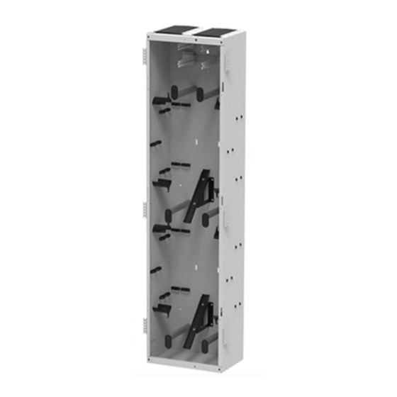
This user manual provides general information
and installation procedures for the Universal
Mount Splice Cabinet, shown at right in 24 tray
and 12 tray sizes with 19-inch mounting brack-
ets. Procedures include:
•
Unpacking the cabinet
•
Mounting the cabinet on a rack or 4-
post frame
•
Mounting the cabinet on a wall
•
Preparing cables for installation
•
Installing cables
•
Setting up splices
This manual also tells how to obtain technical
assistance.
860657162
Rev C
User Manual
24 Tray Cabinet
12 Tray Cabinet
© 2020 CommScope, Inc.
Page 1 of 20
Advertisement
Table of Contents

Subscribe to Our Youtube Channel
Related Manuals for CommScope ODF-SPLCAB-24


Summary of Contents for CommScope ODF-SPLCAB-24
-
Page 1: Table Of Contents
Mounting the cabinet on a wall • Preparing cables for installation • Installing cables • Setting up splices This manual also tells how to obtain technical assistance. 12 Tray Cabinet 860657162 Rev C Page 1 of 20 © 2020 CommScope, Inc. -
Page 2: Product Description
Facility cables are high-fiber-count cables containing rollable ribbons, and of a type suitable for being routed indoors or outdoors. The splice cabinet is available in two sizes: 24 trays (ODF-SPLCAB-24, shown in Figure 1), and 12 trays (ODF- SPLCAB-12), which is analogous in features. - Page 3 A splice tray can be easily removed to a work surface for fiber routing and splicing. The ODF-SPLCAB-24 has two stacks of splice trays. The ODF-SPLCAB-12 has one stack of splice trays.
-
Page 4: Dimensions And Specifications
4-post frame or on a wall 4-post frame or on a wall 17.84 IN. (48.30 CM) 11.54 IN. (29.3 CM) 68.5 IN. (174 CM) 27009-A Figure 3. 24 Tray Universal Mount Splice Cabinet (ODF-SPLCAB-24) Dimensions Page 4 of 20. © 2019 CommScope, Inc. -
Page 5: Typical Application
DIAGRAM IS A FUNCTIONAL SCHEMATIC; IT DOES NOT SPLICE SHOW CABLE TRAYS ROUTING IN (12 IN EACH CABINET. STACK) SPLICE CABINET 97010-A Figure 5. Universal Mount Splice Cabinet Application Example (ODF-SPLCAB-24 shown) Page 5 of 20 © 2019 CommScope, Inc. . -
Page 6: Unpacking And Inspection
Save all shipping containers for use if the equipment requires shipment at a future date. Mounting the Cabinet Note: The 24 tray splice cabinet (ODF-SPLCAB-24) is shown in figures, Same process is valid for the 12 tray splice cabinet (ODF-SPLCAB-12). 3.1 Mounting Options and Tools The Universal Mount Splice Cabinet can be mounted on a 19-inch or 23-inch equipment rack or 4-post frame. - Page 7 Fasten the splice cabinet to the rack with #12-24 screws and lock washers, as shown in Figure MOUNTING BRACKET (6X) 27011-A Figure 7. Mounting the Splice Cabinet on an Equipment Rack Page 7 of 20 © 2019 CommScope, Inc. .
-
Page 8: Mounting On Four-Post Frame
Figure 8. Four Post Installation Mounting Bracket Location Fasten splice cabinet to frame with #12-24 screws and lock washers (Figure MOUNTING BRACKET (6X) 27014-A Figure 9. Mounting the Splice Cabinet on a Four-Post Frame Page 8 of 20. © 2019 CommScope, Inc. -
Page 9: Mounting Cabinet On Wall
TC-96282-IP 3.4 Mounting Cabinet on Wall The 24 tray splice cabinet (ODF-SPLCAB-24) is shown in figures, Same process is Note: valid for the 12 tray splice cabinet (ODF-SPLCAB-12). Figure 10 shows the features of the wall mounting brackets. MOUNTING HOLE (14X) 18.0 IN. - Page 10 Figure 12. Mounting the Splice Cabinet on a Wall Hang the cabinet on the wall by positioning the middle horseshoe opening (shown in Figure 10 on Page 9) on the support screw just installed. Level the cabinet. Page 10 of 20. © 2019 CommScope, Inc.
-
Page 11: Grounding Cabinet
Breakout kits are required for facility cables. The recommended RIBCBOUT kits are described in TC-96271-IP (see “Section 5 on page 20). Page 11 of 20 © 2019 CommScope, Inc. . - Page 12 TC-96282-IP 27021-A Figure 14. Cable Routing in Splice Cabinet Page 12 of 20. © 2019 CommScope, Inc.
-
Page 13: Installing Splice Trays
Lift the red tray support latch up to lower the tray. Refer to Figure Figure 16. Inserting the Splice Tray in the Tray Holder Bracket Page 13 of 20 © 2019 CommScope, Inc. . - Page 14 When done installing trays in a particular tray holder bracket, lift the trays up together and fasten them in place using the hook-and-loop strap. Refer to Figure Figure 18. Securing Tray With Hook-and-Loop Strap Page 14 of 20. © 2019 CommScope, Inc.
-
Page 15: Removing Splice Trays
ARE DIAGRAMMATIC, NOT (284.5 CM) (137.2 CM) PROPORTIONAL ONE SUB-UNIT (288 OR LESS FIBERS) CABLE 27249-A TIE DOWN SECTION INSIDE CABINET MESH TUBING EXPOSED RIBBON FIBERS Figure 19. Facility Cable Breakout Exploded View Page 15 of 20 © 2019 CommScope, Inc. . -
Page 16: Securing Facility Cables Inside Cabinet
4.6 Securing Facility Cables Outside Cabinet Figure Mount the cable clamp bracket 6-8 inches above splice cabinet, as shown in Table 4 For the cable clamp bracket kit catalog number, refer to Page 16 of 20. © 2019 CommScope, Inc. - Page 17 Large / 0.4 - 1.2 in [10 - 30 mm] OSP-CLPFEC-LG OSP-CLPFEC-XL-1 Extra Large / 1.25 - 1.5 in [32 - 38 mm] OSP-CLPFEC-XL-1 OSP-CLPFEC-XL Extra Large / 1.25 - 1.5 in [32 - 38 mm] OSP-CLPFEC-XL Page 17 of 20 © 2019 CommScope, Inc. .
-
Page 18: Loading Splice Trays
Section 4.4 on page 15 and in the installation instructions for the mesh breakout kits (CommScope document number TC- 96271-IP). 144-fiber cables will have 12 ribbons (144-fibers) per mesh tube subunit. All other cables will have 24 ribbons (288-fibers) per subunit. The cable sheath entry point should fall between 6”-8”... - Page 19 23). The fibers from the left side of the cabinet are represented in red and the fibers from the right side are represented in blue in this illustration. FROM FROM POINT POINT PANEL FACILITY STUB CABLE 26910-A Figure 23. Routing on Splice Tray Page 19 of 20 © 2019 CommScope, Inc. .
-
Page 20: Performing Splices
• Ribbon Cable Breakout (RIBCBOUT) Kits User Manual (TC-96271-IP) -- provides a high-level overview of and basic installation instructions for the CommScope RIBC- BOUT (Ribbon Cable Breakout) series ribbon fiber cable breakout kits. • Cable Clamp 19-Inch Bracket Kit Installation Drawing (660105113) -- contains instal- lation instructions for the Cable Clamp 19-Inch Bracket Kit.
Need help?
Do you have a question about the ODF-SPLCAB-24 and is the answer not in the manual?
Questions and answers