Table of Contents
Advertisement
Quick Links
TC-772-IP
Rev A, Mar 2017
www.commscope.com
Content
Fiber optic splice closure
1 Introduction
4.3 Cable + strength member termination
1
Introduction
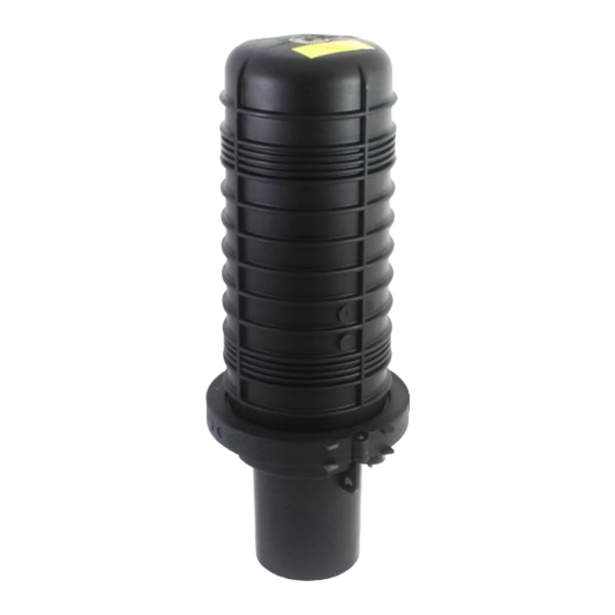
The FOSC-450 is an environmentally sealed enclosure for the fiber management system that provides the function
of splicing in the external network.
The closure is a single ended design made of a thermoplastic material. The base and dome are sealed with a
clamp and pre installed O-ring system. For cable sealing, a wrap-around block with 4 ports is used that contains
a pre-installed gel profile. It can be opened and closed repeatedly without the need to replace the gel.
The maximum single fiber splice capacity of the FOSC 450 A closure is 96 stored on four trays (24 splices per
tray).
FOSC-450A
I N S T A L L A T I O N
I N S T R U C T I O N
Advertisement
Table of Contents

Related Manuals for CommScope FOSC-450A


Summary of Contents for CommScope FOSC-450A
-
Page 1: Table Of Contents
FOSC-450A I N S T A L L A T I O N I N S T R U C T I O N TC-772-IP Fiber optic splice closure Rev A, Mar 2017 www.commscope.com Content 1 Introduction 5 Installation of the gel block... -
Page 2: General
Accessories tail of the seal counter-clockwise until the seal is loose. • FOSC-A-Trays • FOSC-A-Shield-Con-Kit Shield continuity wire • FOSC-450A-MULTI-4/7 • FOSC-450A-3-DROP-KIT Port capacity Secure the frame in the working position. 4-way gel block Lower small ports 2 ports 8 - 22 mm... -
Page 3: Cable Installation
Drop cable preparation Loose buffer tube cable Cable entrance positions 4.2.1 Remove the jacket over a length of 1.2 m , cut the strength Main cables are installed in the two lowest and smaller ports (1,2). The member at a distance of 40 mm from the jacket. drop cables will be placed in the two larger top positions (3,4). - Page 4 Multi-out with the port splitter kit 4.3.2 Insert the cable assembly through the FOSC 450 closure base and position it into the designated port. Capacity: maximum 3 cables Cable range: from 3 – 6 mm 4.2.4 Mark the drop cable(s) 40 mm from the jacket. Align the metal plate with the jacket and wrap it around the cable.
- Page 5 Modular cable (multi-out) Multi-out with the 4/7 kit 4.3.5 Secure the strength member(s) into the strength member attachment. 4.3.6 Insert the drop cable assembly through the FOSC 450 closure base and position it into the designated port. 4.3.7 Position the teeth of the cable retention brackets onto the grommet.
-
Page 6: Tube Routing
4.3.10 Insert the drop cable assembly through the FOSC 450 closure base and position it into the designated port. 4.3.11 Position the teeth of the cable retention brackets onto the felt wrap and secure with the hose clamp. Note: the head of the hose clamp has to be positioned on top of the cable retention bracket. - Page 7 Central tube (loop) 4.4.7 Secure the transportation tube to the tray with tie-wraps. Note: if necessary mark and remove the tube excess. The tube is 15 mm 4.4.4 Route the central tube directly to the basket and secure with tie- onto the tray and has to make a smooth bend around the tray tower.
- Page 8 Central core Tube (single drop) 4.4.11 Route the fibers to the appropriate trays through transportation tubes. 4.4.9 Slide the appropriate transportation tube/spiral tube over the central core (uni-tube) and route it to the basket. 4.4.12 Secure the transportation tubes to the tray with tie-wraps. Note: if necessary mark and remove the tube excess.
- Page 9 Modular cable (multi-out) Loose buffer tube 4.4.13 Strip the loose tube at 450 mm from the jacket. 4.4.14 Select the appropriate size of transportation tube and cut to 300 mm long. 4.4.15 Secure one end of the tube to the tray and route the transportation tube to the basket.
-
Page 10: Installation Of The Gel Block
Installation of the gel block Modular cable (multi-out) Central core tube Make sure the gel seal is not already compressed. Turn the “tail” of the gel seal counter clockwise to ensure that the seal is in the un-compressed position. Squeeze the gel seal to unlatch and open each half one at a time. -
Page 11: Fiber Routing On The Trays
6 Fiber routing on the trays Splicing For heat shrinkable splice protectors: • slide the heat-shrinkable splice protector over one fiber; • fuse the fibers according to local recommendations and procedures; • after the fusion splice is made, install the heat shrinkable splice protection (e.g. - Page 12 • the tray organizer has 6 locations to store splice protectors. Each If a tray for up to 16 ant splice protectors is used (FOSC-A- TRAY-A16) location can hold maximum 4 fusion splice protectors of type smouv- 1120-02 (length 45 mm, installed outer diameter is 2,4 mm) or equivalent.
-
Page 13: Shield Continuity
Shield continuity Routing in the FOSC-ACC-A-TRAY Feeder 7-12 Feeder 1-6 Distribution 7-12 Install the grounding wire as shown on the picture. Distribution 1-6 Feeder and Distribution shown together WRONG! Both of these patterns could cause signal attenuation! Protect with tape. -
Page 14: Capacity Of Baskets
Capacity of baskets 7 loose tubes of 2.8 mm 9.3 Install clamp around dome/base interface. Use the feet of the clamp handle to close the gap in the clamp. 4 loose tubes of 2.8 mm A security lock or tie-wrap may be inserted through the round Closing the closure holes in the handle and clamp to lock the closure. - Page 16 © 2017 CommScope, Inc. All rights reserved. web at www.commscope.com FOSC and all trademarks identified by ® or ™ are registered trademarks or trademarks, respectively, of CommScope, Inc. For technical assistance, customer service, or to report any This document is for planning purposes only and is not intended to modify or supplement any specifications or warranties relating to missing/damaged parts, visit us at: CommScope products or services.
Need help?
Do you have a question about the FOSC-450A and is the answer not in the manual?
Questions and answers