Fluidwell B Series User Manual
Flowrate indicator/totalizer
Hide thumbs
Also See for B Series:
- User manual (32 pages) ,
- Quick reference manual (2 pages) ,
- Quick reference manual (2 pages)
Table of Contents
Advertisement
Quick Links
Advertisement
Table of Contents

Related Manuals for Fluidwell B Series


Summary of Contents for Fluidwell B Series
- Page 1 User manual B-Smart FLOWRATE INDICATOR / TOTALIZER Signal input: pulse, NAMUR or coil flow meter signal Signal outputs: analog reflecting flowrate and scaled pulse reflecting total B-Series - Basic indicators for ordinary locations More info: www.fluidwell.com/bseries.
-
Page 2: Table Of Contents
User manual B-Smart TABLE OF CONTENTS ABOUT THIS MANUAL......................How to use this manual ....................Use of pictograms ......................Warranty and technical support ..................Model Reference ......................SAFETY ............................ Personal safety ....................... End-user responsibilities....................Potential equipment damage ..................Disposal of electronic waste ................... INTRODUCTION........................ - Page 3 B-Smart User manual Battery replacement......................24 7.3.1 Safety instructions ......................24 7.3.2 Battery replacement procedure ..................25 7.3.3 Disposal of batteries ....................... 25 APPENDIX A - TECHNICAL SPECIFICATION ................26 General ........................... 26 Input ..........................27 Output ..........................27 Operational ........................27 APPENDIX B - TROUBLESHOOTING ...................
-
Page 4: About This Manual
● incorrect functioning of the unit or connected instruments. A note informs you of important information. WARRANTY AND TECHNICAL SUPPORT For warranty and technical support on your Fluidwell products, visit our internet site www.fluidwell.com or contact us at support@fluidwell.com. MODEL REFERENCE Hardware version: 03.32.xx... -
Page 5: Safety
B-Smart User manual SAFETY PERSONAL SAFETY ● Risk of electric shock: Only open the unit if all leads are free of potential electrical energy. ● Immediately inform the person responsible for the installation if you disagree with the safety precautions or if you detect errors or danger. END-USER RESPONSIBILITIES ●... -
Page 6: Introduction
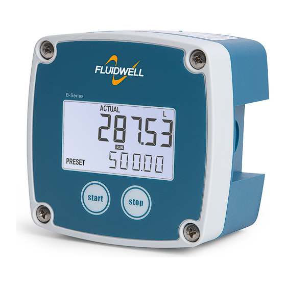
User manual B-Smart INTRODUCTION SYSTEM DESCRIPTION The flow rate indicator / totalizer model B-Smart is a microprocessor-driven instrument designed to show the current flow rate, resettable total, non-resettable accumulated total, and to transmit flow rate and totals. Fig. 1: The B-Smart This manual describes the daily use, configuration and installation of the B-Smart with pulse input from a flow meter. -
Page 7: Installation Example
B-Smart User manual ● Multiple power supply options, including battery and 10-30 V ● Configurable pulse and analog signal outputs. Configuration The B-Smart can be used for many types of application and has a SETUP mode to allow for configuring it to your requirements. See for further information. -
Page 8: Operation
User manual B-Smart OPERATION This product may only be operated by authorized and trained personnel who have read and understood this manual, particularly Section 2: Safety [»5] INTRODUCTION This chapter describes the daily use and operation of the B-Smart. For this, the B-Smart is equipped with a control panel that provides the operator with various functions, information and operating modes. -
Page 9: Displayed Information
B-Smart User manual READY SET-UP PROG READY RATE Fig. 4: Example of display information during process DISPLAYED INFORMATION By pressing the SELECT-key, the operator may scroll through a succession of screens showing various process values. The following table shows the available screens. Selected display Displayed information MAIN SCREEN... -
Page 10: Configuration
The Remote Configuration Tool software package can be downloaded free of charge from our ® ® website at www.fluidwell.com/software, and installed on a Microsoft Windows PC. The package also contains a quick-start manual with detailed instructions to successfully connect the PC and your B-Series. -
Page 11: Changing Configuration Settings
B-Smart User manual CLEAR-key When only a function group is indicated in the display (one digit), this key scrolls through clear the function groups (1. à 2. à 3.) When a function group is entered (two digits in display), this key is used to select the previous function in the list (e.g. -
Page 12: Setup Menu Overview
User manual B-Smart SETUP MENU OVERVIEW TOTAL DEFAULT UNIT L - m3 - kg - lb - GAL - USGAL - bbl - no unit DECIMALS 0 - 3 0.000010 - 9,999,999 K-FACTOR DECIMALS K-FACTOR 0 - 6 RATE DEFAULT UNIT mL - L - m3 - g - kg - ton - GAL - bbl - lb - cf - no unit TIME... -
Page 13: Menu 2: Rate
B-Smart User manual TOTAL Changing the measurement unit will have consequences for operator and setup values. Please note that the K-factor should be checked also. Recalculation is not done automatically. UNIT Determines the measurement unit for (accumulated) total, which is also used in configuration of the scaled pulse output. -
Page 14: Menu 3: Meter
User manual B-Smart 5.4.3 MENU 3: METER METER SIGNAL Selects the type of input sensor pickup / signal. The B-Smart can process several types of input signal. FLOW METER SELECTION CHARACTERISTICS TYPE OF SIGNAL EXPLANATION RESISTANCE FREQ / mV pp REMARKS NPN input 100 kΩ... -
Page 15: Menu 5 D-Out
B-Smart User manual A-OUT TUNE-MAX The initial maximum analog output value is 20 mA. However, this value might differ slightly due to external influences such as temperature for example. The 20 mA value can be tuned precisely with this setting. Before tuning the signal, make sure the analog output is not being used for any application! After pressing SELECT+CLEAR simultaneously, the current will be... -
Page 16: Installation
User manual B-Smart INSTALLATION INSTALLATION / ENVIRONMENTAL CONDITIONS Take the relevant IP classification of the enclosure into account (see identification plate). Even an enclosure rated for IP67 / NEMA Type 4X should NEVER be exposed to strongly varying (weather) conditions. When used in very cold environment or varying climatic conditions, inside the instrument case, take the necessary precautions against moisture. -
Page 17: Mechanical Installation
B-Smart User manual Serial number and year of production The serial number can be reviewed on the identification label, the installation label, or in SETUP . The production date is shown on the label and is also indicated by the first 6.3: OTHER >... -
Page 18: Mounting
User manual B-Smart 6.3.2 MOUNTING Wall mounting The enclosure can be wall mounted with screws using the four available mounting holes. The holes are accessible after removal of the front cover. Fig. 10: Installation - Wall mount A: 4x screw / bolt ●... -
Page 19: Electrical Installation
B-Smart User manual ELECTRICAL INSTALLATION First consult the table with limiting environmental conditions and safety parameters in Section 6.1: Installation / environmental conditions [»16] ● The installation must comply with (inter)national requirements and local ordinances. Within the United States all field wiring must conform to the National Electrical Code, NFPA 70. Within Canada all field wiring must conform to the Canadian Electrical Code. -
Page 20: Terminal Connectors
User manual B-Smart TERMINAL CONNECTORS The following terminal connectors are available on the B-Smart. SENSOR FLOW METER INPUT ANALOG OUTPUT DIGITAL OUTPUT POWER SUPPLY Isolated 4-20 mA Isolated transistor Coil 1.2 V DC 8.2 V DC 10 - 30 V DC Reed switch / NPN 3 V DC Namur... - Page 21 B-Smart User manual Pulse signal NPN The B-Smart is suitable for use with flow meters with an NPN output signal. For reliable pulse detection, the signal should be above 1.4 V or below 1.0 V under all circumstances. It is advised to use a sensor which is normally open, and is closed only for a short period.
-
Page 22: Terminals 5-6: Analog Output
User manual B-Smart Namur signal The B-Smart is suitable for use with flow meters with a Namur signal. The sensor may be powered via the 8.2 V DC sensor supply at terminal 4, or may be powered externally. 8. V DC NAMUR Shield 47 kΩ... -
Page 23: Terminals 9-10: Power Supply
B-Smart User manual 6.5.4 TERMINALS 9-10: POWER SUPPLY Connect an external power supply (10-30 V DC) to terminals 9 and 10. Maximum current will be 25 mA. When power is supplied, the internal battery will not be used, and 8.2 V DC sensor supply becomes available at terminal 4. -
Page 24: Maintenance
User manual B-Smart MAINTENANCE GENERAL DIRECTIONS The B-Smart does not require special maintenance unless it is used in low-temperature applications or surroundings with high humidity (above 90% annual mean). It is the users responsibility to take all precautions to dehumidify the B-Smart in such a way that no condensation will occur, for example by placing a dry silica gel sachet in the casing. -
Page 25: Battery Replacement Procedure
B-Smart User manual 7.3.2 BATTERY REPLACEMENT PROCEDURE Exchange the battery as follows: 1. Open the B-series. See for more information. Section 6.3: Mechanical installation [»17] 2. Hold the cover (1) and carefully remove the battery (2) from its holder (3). Please note that the holder can be made of plastic (as drawn) or of two metal clips. -
Page 26: Appendix A - Technical Specification
User manual B-Smart APPENDIX A - TECHNICAL SPECIFICATION GENERAL DISPLAY Type High intensity reflective numeric and alphanumeric LCD with bright backlight, UV-resistant Note Backlight not available when battery or loop powered Digits 7 with height 12 mm (0.47”) and 11 with height 7 mm (0.28”). Various symbols and measuring units. -
Page 27: Input
B-Smart User manual DIRECTIVES AND STANDARDS EN/BS 61000-6-2 EN/BS 61000-6-3 EN/BS 61326-1 FCC 47 CFR part 15 RoHS EN/BS 50581 EN/BS IEC 63000 IP & TYPE EN/BS 60529 NEMA 250 Note See the applicable Declaration of Conformity or product certificate for specific revisions and publication dates of applicable standards. -
Page 28: Appendix B - Troubleshooting
User manual B-Smart APPENDIX B - TROUBLESHOOTING Table 1 lists and describes how to troubleshoot problems that can occur when installing or operating theB-Smart. Table 2 lists internal alarm codes and conditions signaled by a blinking ALARM flag on the display ). -
Page 29: Appendix C - Legal Information
Last two digits of the year in which the CE marking was affixed: 16. I. Meij, Manager Technology Fluidwell BV ‒ P.O.Box 6, 5460 AA, Veghel, The Netherlands ‒ Voltaweg 23, 5466 AZ, Veghel, The Netherlands Fluidwell BV is ISO9001 certified by DEKRA Certification BV, Meander 1051, 6825 MJ, Arnhem, The Netherlands. -
Page 30: Configuration Settings Log
User manual B-Smart LIST OF CONFIGURATION SETTINGS SETTING DEFAULT DATE: DATE: TOTAL UNIT DECIMALS K-FACTOR DECIMALS K-FACTOR RATE UNIT TIME DECIMALS K-FACTOR DECIMALS K-FACTOR METER SIGNAL coil A-OUT OUTPUT disable RATE-MIN RATE-MAX 99,999 TUNE-MIN Factory set TUNE-MAX Factory set D-OUT MODE DECIMALS AMOUNT... - Page 31 B-Smart User manual NOTES FW_B-SMART_M_v0401-01_EN Page 31...
- Page 32 Fluidwell bv P.O. Box 6 Voltaweg 23 Website: www.fluidwell.com 5460 AA Veghel 5466 AZ Veghel Find your nearest representative: www.fluidwell.com/representatives the Netherlands the Netherlands © Copyright 2024 - FW_B-SMART_M_v0401-01_EN...
Need help?
Do you have a question about the B Series and is the answer not in the manual?
Questions and answers