Fluidwell B Series User Manual
Batch controller
Hide thumbs
Also See for B Series:
- User manual (32 pages) ,
- Quick reference manual (2 pages) ,
- Quick reference manual (2 pages)

Related Manuals for Fluidwell B Series


Summary of Contents for Fluidwell B Series
- Page 1 User manual B-In-Control BATCH CONTROLLER Signal input: pulse, NAMUR or coil flow meter signal Signal outputs: two control outputs B-Series - Basic indicators for ordinary locations More info: www.fluidwell.com/bseries.
-
Page 2: Table Of Contents
User manual B-In-Control TABLE OF CONTENTS ABOUT THIS MANUAL......................How to use this manual ....................Use of pictograms ......................Warranty and technical support ..................Model Reference ......................SAFETY ............................ Personal safety ....................... End-user responsibilities....................Potential equipment damage ..................Disposal of electronic waste ................... INTRODUCTION........................ - Page 3 B-In-Control User manual Battery replacement......................23 7.3.1 Safety instructions ......................23 7.3.2 Battery replacement procedure ..................24 7.3.3 Disposal of batteries ....................... 24 APPENDIX A - TECHNICAL SPECIFICATION ................25 General ........................... 25 Input ..........................26 Output ..........................26 Operational ........................26 APPENDIX B - TROUBLESHOOTING ...................
-
Page 4: About This Manual
● incorrect functioning of the unit or connected instruments. A note informs you of important information. WARRANTY AND TECHNICAL SUPPORT For warranty and technical support on your Fluidwell products, visit our internet site www.fluidwell.com or contact us at support@fluidwell.com. MODEL REFERENCE Hardware version: 03.32.xx... -
Page 5: Safety
B-In-Control User manual SAFETY PERSONAL SAFETY ● Risk of electric shock: Only open the unit if all leads are free of potential electrical energy. ● Immediately inform the person responsible for the installation if you disagree with the safety precautions or if you detect errors or danger. END-USER RESPONSIBILITIES ●... -
Page 6: Introduction
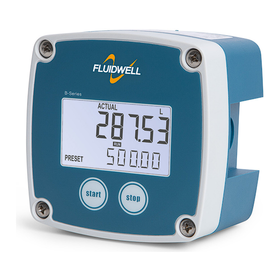
User manual B-In-Control INTRODUCTION SYSTEM DESCRIPTION The batch controller model B-In-Control is a microprocessor-driven instrument designed for batching and filling of small batch sizes up to medium large quantities, as well as showing resettable total and a non-resettable accumulated total. Fig. 1: The B-In-Control This manual describes the daily use, configuration and installation of the B-In-Control with pulse... -
Page 7: Product Features
B-In-Control User manual PRODUCT FEATURES General characteristics ● User friendliness: easy two button operation ● Good readings in full sunlight and darkness through bright backlight ● Mounting flexibility through compact and durable IP65 enclosure for field, wall or meter mounting ●... -
Page 8: Operation
User manual B-In-Control OPERATION This product may only be operated by authorized and trained personnel who have read and understood this manual, particularly Section 2: Safety [»5] INTRODUCTION This chapter describes the daily use and operation of the B-In-Control. For this, the B-In-Control is equipped with a control panel that provides the operator with various functions, information and operating modes. -
Page 9: Batching
B-In-Control User manual Normally, the display is updated once per second. By pressing any key, the display switches to refreshing the information 8 times per second. After 30 seconds of key inactivity, the display returns to the standard refresh rate. ACTUAL READY ALARM... -
Page 10: Displayed Information
User manual B-In-Control Completing the batch process When the actual value reaches the preset quantity, the outputs are switched off and the batch process is finished. The exact moment the outputs are switched depends on the configuration settings for overrun ( SETUP 2: OVERRUN ●... -
Page 11: Configuration
The Remote Configuration Tool software package can be downloaded free of charge from our ® ® website at www.fluidwell.com/software, and installed on a Microsoft Windows PC. The package also contains a quick-start manual with detailed instructions to successfully connect the PC and your B-Series. -
Page 12: Changing Configuration Settings
User manual B-In-Control STOP-key When only a function group is indicated in the display (one digit), this key scrolls through stop the function groups (1. à 2. à 3.) When a function group is entered (two digits in display), this key is used to select the previous function in the list (e.g. -
Page 13: Setup Menu Explanations
B-In-Control User manual OVERRUN DEFAULT TIME 0 - 99 PRECLOSE 0000.000 - 9,999,999 METER DEFAULT SIGNAL coil - reed - NPN - PNP - Namur coil OTHER DEFAULT MODEL fixed BASIC61 SOFTWARE VERSION fixed 03.06.xx SERIAL NUMBER fixed xxxxxxx 0000 - 9999 0000 off - on BACKLIGHT... -
Page 14: Menu 2: Overrun
User manual B-In-Control 5.4.2 MENU 2: OVERRUN Overrun can occur at the end of the batch process, as a result of slowness of a valve / pump. Consequently, the accuracy is less. With this function, the B-In-Control analyses the actual overrun characteristic after every batch. -
Page 15: Installation
B-In-Control User manual INSTALLATION INSTALLATION / ENVIRONMENTAL CONDITIONS Take the relevant IP classification of the enclosure into account (see identification plate). Even an enclosure rated for IP67 / NEMA Type 4X should NEVER be exposed to strongly varying (weather) conditions. When used in very cold environment or varying climatic conditions, inside the instrument case, take the necessary precautions against moisture. -
Page 16: Mechanical Installation
User manual B-In-Control Serial number and year of production The serial number can be reviewed on the identification label, the installation label, or in SETUP . The production date is shown on the label and is also indicated by the first 4.3: OTHER >... -
Page 17: Mounting
B-In-Control User manual 6.3.2 MOUNTING Wall mounting The enclosure can be wall mounted with screws using the four available mounting holes. The holes are accessible after removal of the front cover. Fig. 12: Installation - Wall mount A: 4x screw / bolt ●... -
Page 18: Electrical Installation
User manual B-In-Control ELECTRICAL INSTALLATION First consult the table with limiting environmental conditions and safety parameters in Section 6.1: Installation / environmental conditions [»15] ● The installation must comply with (inter)national requirements and local ordinances. Within the United States all field wiring must conform to the National Electrical Code, NFPA 70. Within Canada all field wiring must conform to the Canadian Electrical Code. -
Page 19: Terminal Connectors
B-In-Control User manual TERMINAL CONNECTORS The following terminal connectors are available on the B-In-Control. SENSOR CONTROL CONTROL FLOW METER INPUT POWER SUPPLY OUTPUT 2 OUTPUT 1 Passive transistor Passive transistor Coil 1.2 V DC 8.2 V DC 10 - 30 V DC Reed switch / NPN 3 V DC Namur... - Page 20 User manual B-In-Control Pulse signal NPN The B-In-Control is suitable for use with flow meters with an NPN output signal. For reliable pulse detection, the signal should be above 1.4 V or below 1.0 V under all circumstances. It is advised to use a sensor which is normally open, and is closed only for a short period.
-
Page 21: Terminals 5-8: Digital Outputs
B-In-Control User manual Namur signal The B-In-Control is suitable for use with flow meters with a Namur signal. The sensor may be powered via the 8.2 V DC sensor supply at terminal 4, or may be powered externally. 8. V DC NAMUR Shield 47 kΩ... -
Page 22: Service Port
User manual B-In-Control 6.5.4 SERVICE PORT A service port enabling configuration of the B-In-Control via an external device such as a laptop is available. Connection to the port should be made with a special communications cable, available through our website or your supplier (accessory ACE02). The service port is not to be connected permanently CONFIG service connector... -
Page 23: Maintenance
B-In-Control User manual MAINTENANCE GENERAL DIRECTIONS The B-In-Control does not require special maintenance unless it is used in low-temperature applications or surroundings with high humidity (above 90% annual mean). It is the users responsibility to take all precautions to dehumidify the B-In-Control in such a way that no condensation will occur, for example by placing a dry silica gel sachet in the casing. -
Page 24: Battery Replacement Procedure
User manual B-In-Control 7.3.2 BATTERY REPLACEMENT PROCEDURE Exchange the battery as follows: 1. Open the B-series. See for more information. Section 6.3: Mechanical installation [»16] 2. Hold the cover (1) and carefully remove the battery (2) from its holder (3). Please note that the holder can be made of plastic (as drawn) or of two metal clips. -
Page 25: Appendix A - Technical Specification
B-In-Control User manual APPENDIX A - TECHNICAL SPECIFICATION GENERAL DISPLAY Type High intensity reflective numeric and alphanumeric LCD with bright backlight, UV-resistant Note Backlight not available when battery or loop powered Digits 7 with height 12 mm (0.47”) and 11 with height 7 mm (0.28”). Various symbols and measuring units. -
Page 26: Input
User manual B-In-Control DIRECTIVES AND STANDARDS EN/BS 61000-6-2 EN/BS 61000-6-3 EN/BS 61326-1 FCC 47 CFR part 15 RoHS EN/BS 50581 EN/BS IEC 63000 IP & TYPE EN/BS 60529 NEMA 250 Note See the applicable Declaration of Conformity or product certificate for specific revisions and publication dates of applicable standards. -
Page 27: Appendix B - Troubleshooting
B-In-Control User manual APPENDIX B - TROUBLESHOOTING Table 1 lists and describes how to troubleshoot problems that can occur when installing or operating theB-In-Control. Table 2 lists internal alarm codes and conditions signaled by a blinking ALARM flag on the display ). -
Page 28: Appendix C - Legal Information
Last two digits of the year in which the CE marking was affixed: 16. I. Meij, Manager Technology Fluidwell BV ‒ P.O.Box 6, 5460 AA, Veghel, The Netherlands ‒ Voltaweg 23, 5466 AZ, Veghel, The Netherlands Fluidwell BV is ISO9001 certified by DEKRA Certification BV, Meander 1051, 6825 MJ, Arnhem, The Netherlands. -
Page 29: Configuration Settings Log
B-In-Control User manual LIST OF CONFIGURATION SETTINGS SETTING DEFAULT DATE: DATE: PRESET UNIT DECIMALS K-FACTOR DECIMALS K-FACTOR OVERRUN TIME PRECLOSE METER SIGNAL coil OTHER MODEL BASIC61 SOFTWARE VERSION 03.06.xx SERIAL NUMBER xxxxxxx 0000 BACKLIGHT FW_B-IN-CONTROL_M_v0401-01_EN Page 29... - Page 30 User manual B-In-Control NOTES Page 30 FW_B-IN-CONTROL_M_v0401-01_EN...
- Page 31 B-In-Control User manual FW_B-IN-CONTROL_M_v0401-01_EN Page 31...
- Page 32 Fluidwell bv P.O. Box 6 Voltaweg 23 Website: www.fluidwell.com 5460 AA Veghel 5466 AZ Veghel Find your nearest representative: www.fluidwell.com/representatives the Netherlands the Netherlands © Copyright 2024 - FW_B-IN-CONTROL_M_v0401-01_EN...
Need help?
Do you have a question about the B Series and is the answer not in the manual?
Questions and answers