Table of Contents
Advertisement
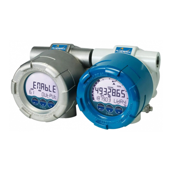
E112-P
EXPLOSION PROOF FLOWRATE INDICATOR / TOTALIZER
with LINEARIZATION
Signal input flowmeter: pulse, Namur and coil
Signal outputs: Analog referenced flowrate and pulse referenced total
Remote control: External reset
Options: Modbus communication
E-Series – Explosion proof indicators for hazardous areas. More info: www.fluidwell.com/eseries
Advertisement
Table of Contents

Subscribe to Our Youtube Channel
Related Manuals for Fluidwell E112-P


Summary of Contents for Fluidwell E112-P
- Page 1 EXPLOSION PROOF FLOWRATE INDICATOR / TOTALIZER with LINEARIZATION Signal input flowmeter: pulse, Namur and coil Signal outputs: Analog referenced flowrate and pulse referenced total Remote control: External reset Options: Modbus communication E-Series – Explosion proof indicators for hazardous areas. More info: www.fluidwell.com/eseries...
-
Page 2: Safety Instructions
Do connect a proper grounding to the aluminum / stainless steel casing as indicated if the E112-P is used on a ship, truck or other application with no ground. The green / yellow wire between the casing and terminal-block may never be removed. -
Page 3: About The Operation Manual
This operation manual describes the standard unit as well as most of the options available. For additional information, please contact your supplier. A hazardous situation may occur if the E112-P is not used for the purpose it was designed for or is used incorrectly. Please carefully note the information in this operating manual indicated by the pictograms: A "warning"... -
Page 4: Table Of Contents
Safety rules and precautionary measures ....................... 2 About the operation manual ..........................3 Contents manual ............................. 4 Introduction ............................. 5 1.1. System description of the E112-P..................5 Operational ............................. 7 2.1. General ..........................7 2.2. Control panel .......................... 7 2.3. -
Page 5: Introduction
Suitability for offshore applications: stainless steel 316L enclosure version. Ease for the Operator: functional information and identical operation as all F / D / N –series of Fluidwell. Ability to process any type of sensor signals, Multiple power supply options to suit any application, including long-life battery supply. - Page 6 Once familiar with one product, you are able to control them all, often without a manual: if you know one – you know them all. The E112-P has been designed to be implemented in many types of applications. For that reason, a SETUP-level is available to configure the E112-P according to your specific requirements.
-
Page 7: Operational
All instructions in this manual are to be observed. Take careful notice of the “Safety rules, instructions and precautionary measures “in front of this manual. This chapter describes the daily use of the E112-P. This instruction is meant for users / operators. 2.2. CONTROL PANEL The following three infra-red keys, operated through glass, are available: Fig. - Page 8 On the side of the collar of the display three black mechanical push buttons are present in the same order as the infra-red keys, PROG/ENTER – SELECT – CLEAR. They operate in the same manner as the infra- red keys. Select Fig. 5: Push buttons Control Panel FW-E112-P-MAN-EN_v0101_08...
-
Page 9: Operator Information And Functions
Note: Be aware that the infra-red keys are locked and will not function. Unlock the infra-red keys as described on page 7. In general, the E112-P will always act at Operator level. The information displayed is dependent upon the SETUP-settings. All pulses generated by the connected flowmeter are measured by the E112-P in the background, whichever screen refresh rate setting is chosen. - Page 10 Fig. 7: Example of low-battery alarm. • Alarm 01-03 ALARM The sign flashes when an alarm situation is active; this can be a low flowrate but also a problem with the product. Please do also consult Appendix B: Problem Solving. FW-E112-P-MAN-EN_v0101_08...
-
Page 11: Configuration
Alternatively, if no keys are pressed for 2 minutes, the unit will exit SETUP automatically. SETUP can be reached at all times while the E112-P remains fully operational. Be aware that in this case any change to the settings may have an influence on the operation. - Page 12 (e.g. 1, 1.1, 1.2, 1.3, 1.4, 1, 2, 3, 3.1 etc.). Scrolling back function group is done by pressing PROG (e.g. 4 , 3 , 2 , 1 ) Scrolling back a sub-function is done by pressing CLEAR (e.g. 1.4, 1.3, 1.2, 1.1), FW-E112-P-MAN-EN_v0101_08...
- Page 13 Note: alterations will only be set after ENTER has been pressed! To return to OPERATOR-level: In order to return to the operator level, PROG will have to be pressed for three seconds. Also, when no keys are pressed for 2 minutes, SETUP will be left automatically. FW-E112-P-MAN-EN_v0101_08...
-
Page 14: Overview Functions Setup Level
1200 - 2400 - 4800 - 9600 SPEED / BAUDRATE 001 - 255 ADDRESS MODE Bus rtu – bus asc - off OTHERS TYPE / MODEL E112-P SOFTWARE VERSION 03:01:xx SERIAL NO. PASS CODE 0000 - 9999 KEYBOARD LOCK enable - disable... -
Page 15: Explanation Of Setup-Functions
This setting determines the scale factor of the Total. This makes it MULTIPLY FACTOR possible to show up to 3 digits more of the Total/accumulated Total. The amount shown is a rounded number. The following can be selected: x1 – x10 – x100 – x1000 FW-E112-P-MAN-EN_v0101_08... -
Page 16: Flowrate
(important for battery powered applications). Note: for low frequency applications (below 10Hz): do not program more than 10 pulses else the update time will be very slow. Note: for high frequency application (above 1kHz) do program a value of 50 or more pulses. FW-E112-P-MAN-EN_v0101_08... -
Page 17: Display
When battery powered, the user can expect reliable measurement over a long period of time. The E112-P has several smart power management functions to extend the (optional) battery life time significantly next to permanently disabling the infra-red keys. The following functions can be set:... -
Page 18: Flowmeter
Page 18 4 - FLOWMETER The E112-P is able to handle several types of input signal. The type of SIGNAL flowmeter signal is selected with SETUP 4.1. Note: The selections "Active pulse input" offer a pulse detection level of 50% of the supply voltage. -
Page 19: Linearize
Most M-factors will be around 1.000000 like 0.945354 or 1.132573. With this setup function, you can easily enable / disable the linearization DISABLE / ENABLE function. For the frequency, following decimal positions can be selected: DECIMALS 00000 - 1111.1 - 222.22 - 33.333 FREQUENCY FW-E112-P-MAN-EN_v0101_08... -
Page 20: Analog Output
/ decreased with the arrow-keys and is directly active. Press ENTER to store the new value. Remark: the analog output value can be programmed “up-side-down” if desired, so 4mA at maximum flowrate and 20mA at minimum flowrate for example! Continued next page >>> FW-E112-P-MAN-EN_v0101_08... -
Page 21: Analog Output (Continued)
1.4 seconds 2.8 seconds 4.5 seconds 9.0 seconds 2.1 seconds 4 seconds 7 seconds 14 seconds 3.5 seconds 7 seconds 11 seconds 23 seconds 5.2 seconds 10 seconds 17 seconds 34 seconds 6.9 seconds 14 seconds 23 seconds 45 seconds FW-E112-P-MAN-EN_v0101_08... -
Page 22: Pulse
0000000 - 111111.1 - 22222.22 - 3333.333 A pulse will be generated every time a certain quantity is added to the AMOUNT total. Enter this quantity here while taking the decimal position of SETUP 7.2 into account. The following can be selected: 0000.000 - 9999999 FW-E112-P-MAN-EN_v0101_08... -
Page 23: Communication (Optional)
1200 - 2400 - 4800 - 9600 baud For communication purposes, a unique identity can be attributed to every BUS ADDRESS E112-P. This address can vary from 1-255. The communication protocol is Modbus ASCII or RTU mode. Select OFF, MODE to disable this communication function. -
Page 24: Installation
Operating Manual before carrying out its instructions. The E112-P may only be operated by personnel who are authorized and trained by the operator of the facility. All instructions in this manual are to be observed. -
Page 25: Dimensions- Enclosure
Page 25 4.3. DIMENSIONS- ENCLOSURE Aluminum / Stainless steel enclosures: Left connection Cablegland options: - M20x1.5 - M25x1.5 - 1/2 NPT - 3/4 NPT Fig. 8: Dimensions aluminum / Stainless Steel enclosures. FW-E112-P-MAN-EN_v0101_08... -
Page 26: Installing The Hardware
Do ground the aluminum / stainless steel enclosure properly as indicated, if the environment in which the E112-P has been installed requires this (i.e. ship, truck). The green / yellow wire between the casing and terminal-block may never be removed. -
Page 27: Seal Conduits/Enclosure
When included in the shipment, the certified blank plugs supplied by Fluidwell shall be used. The E-series can be connected to another Ex d enclosure following the compulsory conditions below: The part which is used for the connection between the two volumes must be Ex-d certified, The connected enclosure must be Ex d certified with its own electrical equipment inside (i.e. -
Page 28: Voltage Selection Sensor Supply
Total power consumption PD: see Appendix A Technical Specifications. Note: 8.2 and 12V DC require a supply voltage of 16V minimum. Note: The output is protected against overload. In case of an overload also the functionality of the E112-P is affected! The voltage is selected with the two switches inside the casing. -
Page 29: Overview Of Terminal Connectors
The following terminal connectors are available: PULSE POWER SUPPLY OUTPUT P1 P2 EXTERNAL POWER ANALOG SENSOR INPUT SIGNAL OUTPUT RS232 RS485 - 2-wire C1 C2 E1 E2 S1 S2 S3 RXD TXD RESET 1.2V 8.2V Fig. 11: Overview of terminal connectors FW-E112-P-MAN-EN_v0101_08... - Page 30 Note: P o l a r i t y insensitive is only available with PD. Fig. 12: Overview of terminal connectors (2) Battery connector Flat cable connector R9 R10 P5 P6 P7 Fig. 13: Overview of terminal connectors Supply board FW-E112-P-MAN-EN_v0101_08...
-
Page 31: Terminal Connectors
SETUP 4.1 Signal (read par. 3.4.) Sine-wave signal (Coil): The E112-P is suitable for use with flowmeters which have a coil output signal. Two sensitivity levels can be selected with the SETUP-function: COIL LO: sensitivity from about 120mVp-p. - Page 32 Pulse-signal PNP / PNP-LP: The E112-P is suitable for use with flowmeters which have a PNP output signal. 3.0V is offered on terminal S3 which has to be switched by the sensor to terminal S2 (SIGNAL). For reliable pulse detection, the pulse amplitude has to go above 1.2V.
- Page 33 Common ground unit NAMUR-signal: The E112-P is suitable for flowmeters with a Namur signal. The standard E112-P is not able to power the Namur sensor, as an external power supply for the sensor is required. However, an 8.2V sensor supply voltage can be provided through terminal P4.
- Page 34 Page 34 Active signals 8.2V and 24V: The E112-P is suitable for flowmeters with an Active signal. The detection levels are 50% of the selected supply voltage; approximately 4V (ACT_8.1) or 12V (ACT_24). Active signal selection may well be desired in case of sensor power supply through terminal P4.
- Page 35 Max. driving capacity 1000 Ohm @ 30VDC. This loop can also be used to power the E112. If only powered by the loop the backlight will not be activated. Isolated 4-20mA analog output INTERNAL EXTERNAL 4-20mA (<3.5mA when disabled) FW-E112-P-MAN-EN_v0101_08...
-
Page 36: Maintenance
(above 90% annual mean). It is the users responsibility to take all precautions to dehumidify the internal atmosphere of the E112-P in such a way that no condensation will occur, for example by placing dry silica-gel sachet in the casing just before closing it. Furthermore, it is required to replace or dry the silica gel periodically as advised by the silica gel supplier. -
Page 37: Label
E-series Indicator / Totalizer but are expected to become available in 2014. Until that time, the FM and CSA logo’s and certification data is not printed on the labels. The specific certification data may change when the certificates become available. FW-E112-P-MAN-EN_v0101_08... -
Page 38: Label With Thread Sizes
TYPE OR MODEL CODING ON THE THREAD SIZE LABEL In addition to the thread sizes the thread size label will also show information regarding the exact model or type code. The code uses letter and digit combinations: FW-E112-P-MAN-EN_v0101_08... -
Page 39: Appendix A: Technical Specifications
When power supply <21V it cannot power the real sensor supply (Terminal P4). Type AH Loop powered, analog output. 10 - 30V DC, Output disabled <3.5mA. Power consumption max. 750mW@25mA at 30V DC. Note: The loop powered analog output cannot power the backlight or the real sensor supply (Terminal P4). FW-E112-P-MAN-EN_v0101_08... - Page 40 K-Factor 0.000010 - 9,999,999 with variable decimal position. Low-pass filter Available for all pulse signals. Linearization 15 positions with interpolation function; Meter-Factor 0.000001 - 9.999999 versus Frequency 0.001 Hz - 9,999 Hz. Option ZF coil sensitivity 10mVpp Option ZG coil sensitivity 5mVpp. FW-E112-P-MAN-EN_v0101_08...
- Page 41 L, m3, Gallons, kg, Ton, lb, bl, cf, RND, ft3, scf, Nm3, Nl, igal - no units Bargraph speedometer 20 blocks, each block is 5% of total span Decimals 0 - 1 - 2 or 3 Time units /sec - /min - /hr - /day FW-E112-P-MAN-EN_v0101_08...
-
Page 42: Appendix B: Problem Solving
Page 42 APPENDIX B: PROBLEM SOLVING In this appendix, several problems are included that can occur when the E112-P is going to be installed or while it is in operation. Flowmeter does not generate pulses: Check: Signal selection SETUP – 4.1, ... -
Page 43: Appendix C: Communication Variables
The tables below show the various variables that can be used for communication. The E112-P is fitted with the Modbus communication protocol and can be equipped with various physical interfaces like RS485 and RS232 (please see device datasheet for available options). - Page 44 Page 44 SETUP VARIABLES OF THE E112-P TOTAL REGs R/W TYPE VALUE / REMARKS unit uint8 0=none 2=m3 0x020 3=kg 4=lb 5=gal 6=usgal 7=bbl decimals uint8 0…3 0x021 K-factor uint32 1...9999999 0x022 Representation: 0.000010…9999999 depending on variable 54: decimals K-factor.
- Page 45 0x063 PULSE OUTPUT REGs R/W TYPE VALUE / REMARKS impulse width uint8 0…9999 0x080 Representation: 0.001 – 9.999 sec Impulse quantity uint8 0…3 0x082 decimals pulse per X quantity uint32 1...9999999 0x081 Representation: 0.000001…9999999 depending on variables 130, 32 FW-E112-P-MAN-EN_v0101_08...
- Page 46 0…9999 0x0A0 model suffix char Representation:ASCII character 0x0AD firmware version uint32 0…999999 0x0A2 Representation: xx.xx.xx serial number uint32 0…9999999 0x0A5 pass code uint16 0…9999 0x0A8 keyboard lock uint8 0=disable 1=enable 0x08B tag number uint32 0...9999999 0x0AA FW-E112-P-MAN-EN_v0101_08...
-
Page 47: Index
............15 decimals ............16 measuring unit ..........15 decimals k-factor ..........16 Total .............. 9, 10 measuring unit ..........16 version software ..........23 time unit ............16 Voltage selection sensor ........28 Flowrate ............9, 10 Frequency............19 FW-E112-P-MAN-EN_v0101_08... -
Page 48: List Of Figures In This Manual
Page 48 LIST OF FIGURES IN THIS MANUAL Fig. 1: Typical application for the E112-P ..................5 Fig. 2: Infra-red keys Control Panel ....................7 Fig. 3: Locked keyboard - infra-red keys ..................7 Fig. 4: On-Off switch infra-red keys ....................8 Fig. -
Page 49: Notes
Page 49 NOTES FW-E112-P-MAN-EN_v0101_08... -
Page 50: Declaration Of Conformity
Page 50 DECLARATION OF CONFORMITY FW-E112-P-MAN-EN_v0101_08... - Page 51 5.2 frequency 0.0Hz M-Factor 1.000000 5.3 frequency 0.0Hz M-Factor 1.000000 5.4 frequency 0.0Hz M-Factor 1.000000 5.5 frequency 0.0Hz M-Factor 1.000000 5.6 frequency 0.0Hz M-Factor 1.000000 5.7 frequency 0.0Hz M-Factor 1.000000 5.8 frequency 0.0Hz M-Factor 1.000000 5.9 frequency 0.0Hz M-Factor 1.000000 FW-E112-P-MAN-EN_v0101_08...
- Page 52 0000 9.5 keyboard lock enabled 9.6 tagnumber 0000000 Fluidwell bv FW-E112-P-MAN-EN_v0101_08 PO box 6 Voltaweg 23 Website: www.fluidwell.com 5460 AA Veghel 5466 AZ Veghel Find your nearest representative: www.fluidwell.com/representatives The Netherlands The Netherlands Copyright Fluidwell bv - 2014 - FW-E112-P-MAN-EN_v0101_08...
Need help?
Do you have a question about the E112-P and is the answer not in the manual?
Questions and answers