Table of Contents
Advertisement
Quick Links
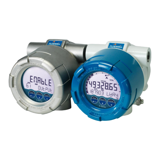
E119-P
TOTALIZER WITH RECEIPT PRINTER DRIVER
and linearization, analog and pulse outputs
Signal input:
Flowmeter - type P: Pulse, NAMUR and coil
Signal outputs:
Analog referenced linearized flowrate
Scaled or unscaled pulse referenced total
Remote control:
External reset with clear-lock
External end delivery with lock function
External print totalizer ticket
External reprint last ticket
E-Series - Explosion proof indicators for hazardous areas
More info: www.fluidwell.com/eseries
Advertisement
Table of Contents

Related Manuals for Fluidwell E119-P


Summary of Contents for Fluidwell E119-P
- Page 1 Analog referenced linearized flowrate Scaled or unscaled pulse referenced total Remote control: External reset with clear-lock External end delivery with lock function External print totalizer ticket External reprint last ticket E-Series - Explosion proof indicators for hazardous areas More info: www.fluidwell.com/eseries...
-
Page 2: Table Of Contents
E119-P TABLE OF CONTENTS ABOUT THIS MANUAL......................How to use this manual ....................Use of pictograms ......................Warranty and technical support ..................Model Reference ......................SAFETY ............................ Personal safety ....................... End-user responsibilities....................Potential equipment damage ..................Disposal of electronic waste ................... - Page 3 E119-P Installation / environmental conditions ................38 Handling the E-Series enclosure ..................39 6.2.1 Main parts ........................39 6.2.2 Identification........................40 6.2.3 Opening, assembling and closing the unit ..............42 6.2.4 Test unit .......................... 43 Mechanical installation....................44 6.3.1 Installation precautions ....................44 6.3.2...
-
Page 4: About This Manual
● incorrect functioning of the unit or connected instruments. A note informs you of important information. WARRANTY AND TECHNICAL SUPPORT For warranty and technical support on your Fluidwell products, visit our internet site www.fluidwell.com or contact us at support@fluidwell.com. MODEL REFERENCE Hardware version: 13.03.xx... -
Page 5: Safety
E119-P SAFETY PERSONAL SAFETY ● Explosion hazard: Never open the unit in a hazardous area when it is connected to a power supply or a consuming device other than the internal battery supply. ● Risk of electric shock: Only open the unit if all leads are free of potential electrical energy. -
Page 6: Introduction
INTRODUCTION SYSTEM DESCRIPTION The flowrate indicator / totalizer model E119-P (also referred to as a unit) is an explosion proof microprocessor-driven instrument designed to linearize the flowmeter’s flow curve and to show the current flowrate, the totalized flow and the accumulated totalized flow, current and previous day total, and several historical day totals. -
Page 7: Product Features
Standard inputs ● One flowmeter with a passive or active pulse, NAMUR or coil signal output can be connected to the E119-P. Several options are available for powering the sensor. ● Two configurable remote control inputs to: ○ Reset total or to lock the ‘clear total’ function. -
Page 8: Ticket Printing
E119-P TICKET PRINTING The E119-P is equipped with an ASCII-based ticket printing feature, which can be used with any printer that accepts serial ASCII-data without control characters. Two types of tickets can be printed: ● Totalizer ticket ● Delivery ticket (with delivery mode enabled) 3.3.1... -
Page 9: Delivery Mode
E119-P 3.3.2 DELIVERY MODE The delivery mode is used to print a delivery ticket with the current totalized value after a command of the operator. The delivery ticket shows specific delivery data (such as a header, start and finish of the delivery and delivery details). -
Page 10: Installation Example
E119-P INSTALLATION EXAMPLE Following parts can be recognized in below installation example. Fig. 5: Installation example E119-P 1. Cover 4. Display 7. Grounding 2. Armed cable connection 5. Optical touch keys 8. Labels 3. Pipe mounting plate 6. Process mount 9. USB connection (option) -
Page 11: Operation
Section 2: Safety [»5] INTRODUCTION This chapter describes the daily use and operation of the E119-P. For this, the unit is equipped with a control panel that provides the operator with various functions, information and operating modes. 4.1.1... -
Page 12: Optical Keys
E119-P The display contains one line with large digits at the top and one line with small digits at the bottom. The top line is mainly used to display key process information, while the bottom line usually displays less important information or system messages. -
Page 13: Backlight
E119-P The Key lock symbol appears at the top of the display to indicate that the keys are locked or disabled: Fig. 7: Key lock symbol To unlock the optical keys, an unlock sequence needs to be performed. Start the unlock sequence by activating any of the optical keys. -
Page 14: Selecting Displayed Information
E119-P CLEAR-key This key is used to clear the value of total or end the current delivery. The CLEAR-key also provides access to the LOG-mode, to review historical day totals. 4.3.2 SELECTING DISPLAYED INFORMATION By pressing the SELECT-key, all relevant information can be reviewed on the display. When no key is pressed for 20 seconds, the display will jump back to the main screen. -
Page 15: Printing Tickets
E119-P 2. Push the CLEAR-key. The display shows ‘PUSH CLEAR’ on the bottom line and the value of Total on the top line. 3. To clear Total, push the CLEAR-key again. To cancel the operation, push any other key or wait for 20 seconds. -
Page 16: Total And Accumulated Total
E119-P 4.4.2 TOTAL AND ACCUMULATED TOTAL Measured flow is added to the counters for Total and Accumulated total continuously. When displayed, Total is shown on the upper line and Accumulated total on the lower line: ● Total will count up to 9.999.999 before rolling over to ‘0’ and can be reset to zero by the operator –... -
Page 17: Operator Alarms
E119-P OPERATOR ALARMS 4.5.1 LOW BATTERY When a battery is used to supply the unit (Type PB) and the battery voltage becomes too low during operation, the battery indicator comes on to warn that the unit is becoming less reliable. It is advised to install a new battery (as soon as possible) as described in Section 7.3: Replace battery [»57]... -
Page 18: Configuration
This chapter describes how technicians can use configuration settings to configure the unit for optimal functionality. Configuration of the E119-P can be done through: ● SETUP-mode using the optical keys (with cover installed) ● SETUP-mode using the mechanical keys (push buttons) (without cover) ●... -
Page 19: Configuring Using Pc Configuration Tool
E119-P 5.2.1 CONFIGURING USING PC CONFIGURATION TOOL Configuration of the E119-P can be done using a PC with our free of charge Remote Configuration Tool software. Consult for details. Connection to a PC is Section D: Remote Configuration Tool [»71] made by means of the communication port, located at the back side of the MEM. -
Page 20: Saving Battery Lifetime (Type Pb)
E119-P Fig. 15: Disable switch for optical keys Use this switch to permanently disable the optical keys: ● Enable: move to the right / ON position. ● Disable: move to the left / OFF position. 5.2.4 SAVING BATTERY LIFETIME (TYPE PB) In case of a battery powered application, lifetime of the battery is an important subject. -
Page 21: Changing Configuration Settings
E119-P The following image shows the layout of the menu structure: SELECT CLEAR PROG CLEAR Fig. 16: SETUP menu layout and navigation Navigate the SETUP menu with the following functions: PROG-key When a menu item is selected (e.g. 1.1), this key is used to start the programming sequence. -
Page 22: Returning To Operator Mode
E119-P SELECT-key + CLEAR-key SELECT CLEAR The combination of the SELECT-key and CLEAR-key is used to select a negative value. When a value can also be entered as a negative number, pressing the SELECT- key and CLEAR-key simultaneously will toggle the ‘–‘ (minus) sign on and off. -
Page 23: Setup Menu Overview
E119-P SETUP MENU OVERVIEW All unit settings can be configured from the control panel. You can also use the Remote Configuration Software, which can be downloaded from our website or is available from your supplier (see Section D: Remote Configuration Tool [»71]... - Page 24 E119-P ANALOG OUTPUT DEFAULT OUTPUT enable, disable disable RATE MIN (4MA) 0.000 - 9999999 RATE MAX (20MA) 0.000 - 9999999 99999 FILTER 01 - 99 (01 = off) CUT-OFF 0.0 - 9.9 % 0.0 % TUNE MIN (4MA) 0000 - 9999...
-
Page 25: Setup Menu Explanations
E119-P SETUP MENU EXPLANATIONS 5.5.1 MENU 1: TOTAL First set up the flowmeter in as this directly affects the settings/measurement units in 4: FLOWMETER the Total menu. If the measurement unit is changed in , the unit in will change to 4.2: FLOWMETER >... -
Page 26: Menu 2: Flowrate
E119-P TOTAL 1.8 PREVIOUS DAY Shows the amount/volume of totalized product between the last contract TOTAL hour and the contract hour before that. This totalizer cannot be reset to zero. Section 4.4.3: Current day total and Previous day total [»16] information on reviewing more historical day totals. -
Page 27: Menu 3: Display
E119-P FLOWRATE 2.6 CUT-OFF Determines a minimum threshold for the required flow. If during this time less than XXX pulses are generated as set in 2.5: FLOWRATE > CALCULATION the flowrate will be displayed as zero. The cut-off time has to be entered in seconds. The maximum time is 999.9 seconds (approximately 15 minutes). -
Page 28: Menu 4: Flowmeter
5.5.4 MENU 4: FLOWMETER To simplify the configuration of the Flowmeter, Total and Flowrate settings, the E119-P has an automatic unit conversion feature. To use this feature, you only have to enter the average K-factor and the related measurement unit. - Page 29 E119-P FLOWMETER 4.1 SIGNAL Selects the type of flowmeter pickup / signal. The unit can process several types of input signal. The settings with LP are used to apply a built-in low- pass filter. Also see Section 6.4.10: Terminals S1-S3: Flowmeter input [»52] for more information.
-
Page 30: Menu 5: Linearization
E119-P FLOWMETER 4.4 K-FACTOR Converts the flowmeter pulse signals to a quantity. The K-factor is based on the number of pulses generated by the flowmeter per measurement unit selected in 4.3: FLOWMETER > UNIT The more accurate the K-factor, the more accurate the system. -
Page 31: Menu 6: Remote Control Inputs
E119-P Entering linearization points A table of 15 linearization points can be entered into the unit. It is advised to enter the linearization points in increasing order of frequency; however, this is not mandatory. The linearization points are usually located at frequencies where the linear behavior of the flowmeter changes. Linearization points that are not used can be disabled by entering a frequency of 0 Hz. - Page 32 E119-P ANALOG OUTPUT 7.1 OUTPUT If the analog output is not used, it can be disabled to minimize power consumption and save battery life. When the output is disabled, a current of about 2 mA is generated and the unit can still be supplied from this signal (provided a power supply is connected).
-
Page 33: Menu 8: Pulse Output
E119-P ANALOG OUTPUT 7.5 CUT-OFF A low flow cut-off can be set as a percentage of the full range of 16 mA, for example, to ignore leakage. When the flow is less than the required rate, the current will be the minimum signal (4 mA, or 20mA when the analog output is programmed ‘up-side-down’). -
Page 34: Menu 9: Communication
CLEAR key to set the digits. 5.5.9 MENU 9: COMMUNICATION The E119-P can be equipped with a communication interface to print a ticket (Type CB/CH/CU). Alternatively, the communication mode can be set to use the Modbus protocol. See Section C: for a detailed explanation of the protocol, data types, and available Modbus communication [»64]... -
Page 35: 5.5.10 Menu 10 Ticket
E119-P COMMUNICATION 9.9 START ROW This setting is used to print up to 9 empty lines before printing the receipt. 9.A END ROW This setting is used to print up to 9 empty lines after printing the receipt. 9.B FORM FEED This setting is used to send a form feed (character 12 / 0x0C) after a receipt is printed. -
Page 36: 5.5.11 Menu 11: Others
E119-P 10 TICKET 10.8 DELIVERY MODE The delivery mode is used to print a delivery ticket. The value of the Total is used as the delivered value. The following can be selected: Disable – deliveries are disabled and the operator can clear the totalizer ●... - Page 37 E119-P 11 OTHERS 11.7 KEY LOCK To prevent misuse of the optical keyboard it can be locked automatically after 30 seconds by enabling this function. In battery supplied applications, the backlight can come on each time the keyboard is activated. As this can quickly degrade the battery, it is advised to leave the keyboard lock function enabled so that the backlight only comes on when an optical key is pressed for at least one second.
-
Page 38: Installation
Personnel must read and understand this Operating Manual before carrying out its instructions. ● The E119-P may only be operated by personnel who are authorized and trained by the operator of the facility. All instructions in this manual are to be observed. -
Page 39: Handling The E-Series Enclosure
E119-P HANDLING THE E-SERIES ENCLOSURE 6.2.1 MAIN PARTS Fig. 18: Exploded view 1. Cover 5. Body 2. Main Electronics Module (MEM) 6. Grounding terminal 3. Battery 7. Label 4. Supply Module (RSM or BSM) Fig. 19: Main Electronic Module and two types of Supply Module (BSM, RSM) 1. -
Page 40: Identification
E119-P 6.2.2 IDENTIFICATION Your product is supplied with two external and several internal labels. Configuration label All E-Series enclosures are supplied with a weatherproof configuration label placed on the outside of the unit. Information on this label includes the configuration options chosen for your product. - Page 41 E119-P Installation labels At the inside, several labels can be found. These labels indicate serial number of the electronics, product configuration and connectors, and more. The MEM is supplied with two labels. Fig. 22: Example MEM labeling The Supply Module is also labeled. Depending on product type your product can be supplied with an RSM or a BSM.
-
Page 42: Opening, Assembling And Closing The Unit
E119-P 6.2.3 OPENING, ASSEMBLING AND CLOSING THE UNIT Explosion risk: never open the housing when explosive atmosphere is present. Safety risk: do not open an installed enclosure when circuits are alive. Opening the cover 1. Loosen the fixing screw. 1,5mm 2. -
Page 43: Test Unit
E119-P Re-assembling the unit 1. If applicable: check that the battery is installed correctly in the supply module BSM/RSM and that the battery cable is correctly inserted into its connector. See Section 7.3: Replace for battery replacement. battery [»57] 2. If applicable: plug the cable connectors with connected wiring into the RSM. -
Page 44: Mechanical Installation
● All NPT threads comply with ANSI/ASME B1.20.1. Connecting enclosures and mounting on flowmeters The E119-P may be connected to another certified enclosure under following conditions: ● The connected enclosure is certified for the used type of protection and certified for its own internal electrical equipment (i.e. -
Page 45: Mechanical Dimensions
E119-P 6.3.2 MECHANICAL DIMENSIONS 112mm / 4.41” Left connection Right connection M20x1.5 M20x1.5 M25x1.5 M25x1.5 ½” NPT ½” NPT ¾” NPT ¾” NPT Bottom connection M20x1.5 M25x1.5 ½” NPT ¾” NPT 1” NPT 70mm / 2.76” 148mm / 5.83” Fig. 25: Mechanical dimensions of the E-Series enclosure 6.3.3... - Page 46 E119-P When mounting the unit, leave the cover on as much as possible to prevent damage to the thread winding. Only remove cover and MEM after mounting. The following options are available to mount the unit: ● Directly on a panel.
-
Page 47: Electrical Installation
E119-P Mount unit on a wall 1. Use the wall mount accessories (ACE03) to attach the unit as shown and follow the Assembly Instructions as supplied with the accessory. 2. Remove the cover and the MEM (see Section 6.2.3: Opening, assembling and closing the unit [»42]... -
Page 48: Grounding Of The Enclosure
E119-P Electrical precautions ● Ensure the unit is correctly wired according to the wiring diagrams and complies with local codes and regulations. ● A suitable power supply should be considered in end-use equipment to power the unit. This supply should comply with a limited-energy circuit (maximum available current of 8 A) such as a “SELV”... -
Page 49: Voltage Selection Sensor Supply
E119-P Supply voltage Maximum supply Type Input Remarks range current PD-OR 24-27 VDC 110 mA With relay(s) and sensor supply PD-OT 9-27 VDC 75 mA Without relay(s), with sensor supply 9-27 VDC 50 mA Without relay(s) and sensor supply A1/A2... -
Page 50: Terminal Connectors - Mem
E119-P Power supply 10 – 30 V DC (OFF = right position) External sensor supply voltage Required supply voltage 8.2 V DC (max. output 20 mA) 9 – 27 V DC 12 V DC (max. output 30 mA) 13 – 27 V DC... -
Page 51: Terminal Connectors - Rsm
E119-P 6.4.6 TERMINAL CONNECTORS – RSM The following terminal connections are available for Relay Supply Module (RSM; option OR). POWER PULSE OUTPUT REQUIREMENTS PD: 9 - 27V DC* OR: Relay output* COM5 PX: 9 - 27V DC *Type OR requires 24-27V DC and power supply via P5-P6 instead of P1-P2 Fig. 30:... -
Page 52: 6.4.10 Terminals S1-S3: Flowmeter Input
E119-P Type OT One passive transistor output (D1) is available with a maximum pulse frequency of 500 Hz. Max. driving capacity 300 mA @ 50 VDC. ● Terminals R1 and R3 are common ground (GND) terminals. ● When retransmit mode is selected the max. frequency is 10kHz with a 50% duty cycle and a minimum on and off- time of 50µs. - Page 53 E119-P Sine-wave signal (Coil) The unit can be used with flowmeters which have a coil output signal. Two sensitivity levels can be selected (see SETUP 4.1: FLOWMETER > SIGNAL [»29] ● COIL LO: sensitivity 90 mVpp. ● COIL HI: sensitivity 20 mVpp. (type ZF offers sensitivity 10 mVpp; type ZG offers sensitivity 5 mVpp).
- Page 54 E119-P Power supply type PD provides a sensor supply voltage of 8.2, 12, or 24 VDC. ↓ J1-J2 8.2 ; 12V; 24V ↓ PNP-LP* ┴ Common system ground Fig. 35: Terminals S1-S3 and P3: Pulse signal input PNP Reed switch The unit can be used with flowmeters which have a reed switch. To avoid pulse bounce from the reed switch, it is advised to select REED LP –...
-
Page 55: 6.4.11 Terminals E1-E3: Remote Control Inputs - Type Ir
E119-P Active signals 8.2 V and 24 V The unit is suitable for flowmeters with an Active signal. The detection levels are about 50% of the selected supply voltage; approximately 4 V (ACT_8.1) or 12 V (ACT_24). See SETUP for more information. - Page 56 E119-P When the output is disabled, the current is by default limited to 2 mA. Max. driving capacity 1000 Ohm @ 27 VDC. If only powered by the loop, the backlight will not be activated. The total loop resistance may not exceed 1000 Ohm and may not be less than 330 Ohm (at 30 mA).
-
Page 57: Maintenance
) before proceeding. Section 2: Safety [»5] If the E119-P is damaged or faulty, it cannot be repaired by the user and must be replaced with an equivalent certified product. Repairs can only be carried out by the manufacturer or their authorized agent. -
Page 58: Replace Clock Battery (Type Zl)
E119-P Remove old battery from BSM/RSM 1. Disconnect the battery connector cable from the Supply module. 2. Carefully remove the battery from the holder. 3. Store the old battery in a small plastic bag (e.g. the bag the new battery came in) or install an insulation tape over the battery connector to prevent a short circuit. -
Page 59: Appendix A - Technical Specification
E119-P APPENDIX A - TECHNICAL SPECIFICATION GENERAL DISPLAY Type High intensity numeric and alphanumeric LCD, UV-resistant, with bright backlight (intensity adjusted via the keypad) Digits Seven 12 mm (0.47”) and eleven 7 mm (0.28”). Various symbols and measuring units. Dimensions Ø... -
Page 60: Input
E119-P SENSOR EXCITATION Type AH/PB/PX Terminal S3: 3 VDC for pulse signals and 1.2 VDC for coil pick-up, I max. 100 μA. This is not a real sensor supply. Only suitable for sensors with a very low power consumption like coils (sine wave) or reed switches. -
Page 61: Standards And Approvals
E119-P FLOW RATE Digits 7 digits Bar graph 20 blocks, each block is 5% of total span speedometer Decimals 0 – 1 - 2 or 3 Time units /sec - /min - /hr - /day STANDARDS AND APPROVALS APPLICABLE DIRECTIVES, LEGISLATION AND STANDARDS EU Directives Section E: Legal information [»72]... -
Page 62: Appendix B - Troubleshooting
E119-P APPENDIX B - TROUBLESHOOTING Table 1 lists and describes how to troubleshoot problems that can occur when installing or operating the unit. Table 2 lists internal alarm codes and conditions signaled by a blinking ALARM icon on the display. The alarm code can be displayed by pushing the SELECT-key repeatedly until the ALARM internal alarm screen is shown. - Page 63 E119-P Table 2: Internal alarms When multiple alarms occur, the error code shown is the sum of the error codes as given below. For example 0048 is a combination of error code 0016 and 0032. Alarm Explanation 0001 Display error...
-
Page 64: Appendix C - Modbus Communication
E119-P APPENDIX C - MODBUS COMMUNICATION INTRODUCTION The product is fitted with the Modbus communication protocol and can be equipped with various physical interfaces like RS485 and RS232 (please see device datasheet for available options). The tables below show the various variables that can be accessed through the communication. -
Page 65: Runtime Variables Of The Unit
Representation: unit, decimals depending on variables 32, 33 Note: The list of runtime variables shown above can be read as one contiguous list of registers. Unused registers return 0. RUNTIME VARIABLES OF THE E119-P - FLOATING POINT BASED 32 BIT – CONTIGUOUS READ HOLDING NO. -
Page 66: Configuration Variables Of The Unit
E119-P RUNTIME VARIABLES OF THE E119-P - FLOATING POINT BASED 32 BIT – CONTIGUOUS READ [d] 6406 46407 flow rate float32 0... 9999999 [h] 0x1906 Representation: unit and time depending on variables 48, 49 [d] 6408 46409 current day total float32 0... - Page 67 E119-P MODBUS-REGISTERS: TOTAL [d] 1052 41053 clear total uint16 000...999 [h] 0x041C password Setting 000 disables the clear total password feature. [d] 2146 42147 contract hour uint16 0...23 Hour [h] 0x0862 [d] 2208 42209 current day total uint64 0.000 ... 99999999999...
- Page 68 E119-P MODBUS-REGISTERS: FLOWMETER [d] 1050 41051 K-factor unit uint16 0=none 3=US GAL 6=OilBBL 9=LB [h] 0x41A 4=I GAL 7=kg 10=US ton 5=CF 8=ton [d] 1046 41047 K-factor uint32 1…9999999 [h] 0x416 Representation: 0.000010…9999999 depending on variable 54: decimals K-factor [d] 1049...
- Page 69 E119-P MODBUS-REGISTERS: PULSE OUTPUT HOLDING NO. OF VARIABLE TYPE VALUES / REPRESENTATION / REMARKS ADDRESS REGISTER REG’S [d] 141 40142 pulse mode uint16 0=disable 1=scaled 2=retrans [h] 0x08D [d] 128 40129 pulse time width uint16 0…9999 [h] 0x080 Representation: 0.001…9.999sec...
- Page 70 E119-P MODBUS-REGISTERS: TICKET [d] 1612 41613 ticket nr uint32 1…9999999 [h] 0x64C Representation: number of last printed ticket. [d] 1604 41605 auto print uint16 0=disable 1=contract [h] 0x644 hour [d] 1611 41612 print daily total uint16 0=no print 1=print [h] 0x64B...
-
Page 71: Appendix D - Remote Configuration Tool
DOWNLOAD AND INSTALL The Remote Configuration Tool software package can be downloaded from our website at www.fluidwell.com/software and installed using the installation program. The installation also contains a Quickstart manual which gives detailed instructions on how to achieve a successful connection between PC and MEM. -
Page 72: Appendix E - Legal Information
E119-P APPENDIX E - LEGAL INFORMATION EU DECLARATION OF CONFORMITY Page 72 FW_E119-P_M_v0301-02_EN... - Page 73 E119-P NOTES FW_E119-P_M_v0301-02_EN Page 73...
- Page 74 E119-P Page 74 FW_E119-P_M_v0301-02_EN...
- Page 75 E119-P FW_E119-P_M_v0301-02_EN Page 75...
- Page 76 Fluidwell bv P.O. Box 6 Voltaweg 23 Website: www.fluidwell.com 5460 AA Veghel 5466 AZ Veghel Find your nearest representative: www.fluidwell.com/representatives the Netherlands the Netherlands © Copyright 2022 - FW_E119-P_M_v0301-02_EN...
Need help?
Do you have a question about the E119-P and is the answer not in the manual?
Questions and answers