Table of Contents
Advertisement
Quick Links
F113-A-AP-Hx-OS-PD-Xx-Zx
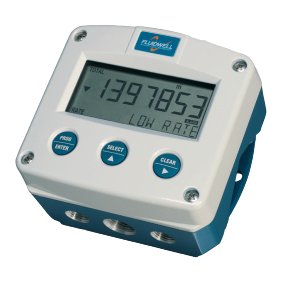
FLOWRATE INDICATOR / TOTALIZER
WITH FOUR HIGH / LOW FLOWRATE ALARMS
Signal input flowmeter: (0)4-20mA
Analog output: (0)4-20mA / 0-10V reflecting flowrate
Switch outputs: four scaled pulse or flowrate alarm outputs
Options: Modbus communication and backlight
F-Series - Field mounted indicators for safe and hazardous areas. More info: www.fluidwell.com/fseries
Advertisement
Table of Contents

Related Manuals for Fluidwell F113-A-AP-H Series


Summary of Contents for Fluidwell F113-A-AP-H Series
- Page 1 WITH FOUR HIGH / LOW FLOWRATE ALARMS Signal input flowmeter: (0)4-20mA Analog output: (0)4-20mA / 0-10V reflecting flowrate Switch outputs: four scaled pulse or flowrate alarm outputs Options: Modbus communication and backlight F-Series - Field mounted indicators for safe and hazardous areas. More info: www.fluidwell.com/fseries...
-
Page 2: Safety Instructions
Page 2 SAFETY INSTRUCTIONS Any responsibility is lapsed if the instructions and procedures as described in this manual are not followed. LIFE SUPPORT APPLICATIONS: The F113-A is not designed for use in life support appliances, devices, or systems where malfunction of the product can reasonably be expected to result in a personal injury. -
Page 3: About The Operation Manual
Manual HF113AEN_OS_v0501_05 © Copyright 2011 Fluidwell bv - The Netherlands. Information in this manual is subject to change without prior notice. The manufacturer is not responsible for mistakes in this material or for incidental damage caused as a direct or indirect result of the delivery, performance or use of this material. -
Page 4: Table Of Contents
Page 4 CONTENTS MANUAL Safety instructions ............................2 Disposal ..............................2 Safety rules and precautionary measures ....................... 2 About the operation manual ..........................3 Contents manual .............................. 4 Introduction ..........................5 1.1. System description of the F113-A-OS ................... 5 Operational ..........................7 2.1. -
Page 5: Introduction
Page 5 INTRODUCTION 1.1. SYSTEM DESCRIPTION OF THE F113-A-OS Functions and features The flowrate / totalizer model F113-A-OS is a microprocessor driven instrument designed to display flowrate, total and accumulated total as well as the monitoring of the flowrate for high / low values. This product has been designed with a focus on: ... - Page 6 Page 6 Configuration of the unit The F113-A-OS was designed to be implemented in many types of applications. For that reason, a SETUP-level is available to configure your F113-A-OS according to your specific requirements. SETUP includes several important features, such as Span, measurement units etc. All setting are stored in EEPROM memory and will not be lost in the event of power failure or a drained battery.
-
Page 7: Operational
Page 7 OPERATIONAL 2.1. GENERAL The F113-A-OS may only be operated by personnel who are authorized and trained by the operator of the facility. All instructions in this manual are to be observed. Take careful notice of the " Safety rules, instructions and precautionary measures " in the front of this manual. -
Page 8: Operator Information And Functions
Page 8 2.3. OPERATOR INFORMATION AND FUNCTIONS In general, the F113-A-OS will always function at Operator level. The information displayed is dependant upon the SETUP-settings. The signal generated by the connected flowmeter is measured by the F113-A-OS in the background, whichever screen refresh rate setting is chosen. After pressing a key, the display will be updated very quickly during a 30 second period, after which it will slow- down again. - Page 9 Page 9 Programming the flowrate alarm values Note: This function might not be immediately accessible due to a configuration setting. When the SELECT-key is pressed a few times, following flowrate alarm values are displayed: low-low flowrate alarm (LL): enter here 20 L/min for example, ...
-
Page 10: Configuration
Page 10 CONFIGURATION 3.1. INTRODUCTION This and the following chapters are exclusively meant for electricians and non-operators. In these, an extensive description of all software settings and hardware connections are provided. Mounting, electrical installation, start-up and maintenance of the instrument may only be carried out by trained personnel authorized by the operator of the facility. - Page 11 Page 11 Matrix structure SETUP-level: SCROLLING THROUGH SETUP-LEVEL Selection of function-group and function: SETUP is divided into several function groups and functions. Each function has a unique number, which is displayed below the word "SETUP" at the bottom of the display. The number is a combination of two figures. The first figure indicates the function-group and the second figure the sub-function.
- Page 12 Page 12 To change or select a value: To change a value, use to select the digits and to increase that value. To select a setting, both and can be used. If the new value is invalid, the increase sign or decrease-sign will be displayed while you are programming.
-
Page 13: Overview Functions Setup Level
Page 13 3.2.2. OVERVIEW FUNCTIONS SETUP LEVEL SETUP FUNCTIONS AND VARIABLES TOTAL UNIT L - m3 - kg - lb - GAL - USGAL - bbl - no unit DECIMALS 0 - 1 - 2 - 3 (Ref: displayed value) SPAN 0.000001 - 999,999 unit/second DECIMALS SPAN... -
Page 14: Explanation Of Setup-Functions
Page 14 3.2.3. EXPLANATION OF SETUP-FUNCTIONS 1 - TOTAL MEASUREMENT UNIT SETUP - 11 determines the measurement unit for total, accumulated total and pulse output. The following units can be selected: L - m3 - kg - lb. - GAL - USGAL - bbl - _ (no unit). Alteration of the measurement unit will have consequences for operator and SETUP-level values. -
Page 15: Flowrate
Page 15 2 - FLOWRATE The settings for total and flowrate are entirely separate. In this way, different units of measurement can be used for each e.g. cubic meters for total and liters for flowrate. The display update time for flowrate is one second or more. Note: these settings also influence the analog output. -
Page 16: Alarm
Page 16 3 - ALARM With these settings, it is determined how the flowrate will be monitored and the functionality of the relay outputs (terminals 10-17) be determined. Note: for relay output functions: read also SETUP 8 “relays”. FLOW ZERO When the flowrate is zero, then it is possible to ignore or disable the flowrate monitoring. -
Page 17: Display
Page 17 4 - DISPLAY SET ALARM This function determines if the flowrate alarm values can be set at both Operator level and SETUP-level or SETUP-level only. If SETUP has been selected, the alarm values are still visible for the Operator but can not be changed. -
Page 18: Flowmeter
Page 18 5 - FLOWMETER SIGNAL The F113-A can process the 4-20mA signal in two ways: Interpolation: the signal is processed linear R = S x I Square root: for differential pressure √ R = S where: R = Rate: the calculated flowrate S = Span: the maximum flowrate at 20mA. - Page 19 Page 19 6 - FLOWMETER (CONTINUED) CUT-OFF To ignore e.g. leakage of the flow or vibration, a low-flow cut-off can be set as percentage over the full range of 16mA (or 20mA / 10V). When the analog value is less then required with this setting, the signal will be ignored.
-
Page 20: Analog Output
Page 20 7 - ANALOG OUTPUT A linear analog (0)4-20mA or 0-10V signal is generated according to the flowrate with a 10 bits resolution. The settings for flowrate (SETUP - 2) influence the analog output directly. The relationship between rate and analog output is set with the following functions: DISABLE / ENABLE The analog output can be disabled. -
Page 21: Relay Output
Page 21 7 - ANALOG OUTPUT (CONTINUED) FILTER This function is used to stabilize the analog output signal. The output value is updated every 0.1 second. With the help of this digital filter a more stable but less precise reading can be obtained. The filter principal is based on three input values: the filter level (01-99), the last analog output value and the last average value. -
Page 22: Communication (Optional)
Page 22 8 - RELAY OUTPUT (CONTINUED) PERIOD TIME The period time determines the time that the relay will be switched; in PULSE OUTPUT other words the pulse length. The minimum time between the pulses is as long as the period time. One period is approx. -
Page 23: Installation
Page 23 INSTALLATION 4.1. GENERAL DIRECTIONS Mounting, electrical installation, start-up and maintenance of this instrument may only be carried out by trained personnel authorized by the operator of the facility. Personnel must read and understand this Operating Manual before carrying out its instructions. ... -
Page 24: Dimensions- Enclosure
Page 24 4.3. DIMENSIONS- ENCLOSURE Aluminum enclosures: 75 mm (2.95") 112 mm (4.40") 130 mm (5.12") 12mm 12mm 30mm 30mm 24mm 24mm M20 x 1,5 6 x M12 36mm 36mm 30mm 30mm M16 x 1,5 M16 x 1,5 1/2"NPT M20 x 1,5 0.12"... - Page 25 Page 25 GRP enclosures: 75 mm (2.95") 112 mm (4.40") 130 mm (5.12") HK back box: (flat bottom) 75 mm (2.95") 118 mm (4.65”) 25mm 25mm D=20mm D=20mm 12mm 12mm 30mm 30mm 24mm 24mm D=12mm D=16mm D=16mm D=20mm 36mm 36mm 0.12”...
-
Page 26: Installing The Hardware
Page 26 4.4. INSTALLING THE HARDWARE 4.4.1. INTRODUCTION Electro static discharge does inflict irreparable damage to electronics! Before installing or opening the unit, the installer has to discharge himself by touching a well-grounded object. This unit must be installed in accordance with the EMC guidelines (Electro Magnetic Compatibility). -
Page 27: Voltage Selection Sensor Supply
Page 27 4.4.2. VOLTAGE SELECTION SENSOR SUPPLY Option PD: Sensor supply: 3.2V, 8.2V, 12V or 24 V: With this option, a real power supply for the sensor is available. The sensor can be powered with 8.2, 12 or 24 V DC (max. 50mA@24V). The voltage is selected by the three switches inside the enclosure. - Page 28 Page 28 REMARKS TERMINAL CONNECTORS: Terminal GND- 01- 02; power supply - only available with option PD: erminal PTION SENSOR SUPPLY PD 24V AC 8.2, 12, 24V max 50mA ◊ PD 24V DC 8.2, 12, 24V max 50mA ◊ Note PD do not use a AC autotransformer (Spartrafo) without a galvanic isolation.
- Page 29 Page 29 Terminal 08-09 analog output (passive) (SETUP 7) : A 4-20mA current-sinking signal proportional to the level is available as standard. A DC power supply should be connected to terminal 08 and 09, the current is then regulated by unit).
- Page 30 Page 30 Terminal 26-31: type CB / CH / CI / CT - communication RS232 / RS485 / TTL (option) Full serial communications and computer control in accordance with RS232 (length of cable max. 15 meters) or RS485 (length of cable max. 1200 meters) is possible. Read the Modbus communication protocol and Appendix C.
-
Page 31: Maintenance
Page 31 MAINTENANCE 5.1. GENERAL DIRECTIONS Mounting, electrical installation, start-up and maintenance of the instrument may only be carried out by trained personnel authorized by the operator of the facility. Personnel must read and understand this Operating Manual before carrying out its instructions. ... -
Page 32: Appendix A: Technical Specification
Page 32 APPENDIX A: TECHNICAL SPECIFICATION GENERAL Display Type High intensity reflective numeric and alphanumeric LCD, UV-resistant. Digits Seven 17mm (0.67") and eleven 8mm (0.31"). Various symbols and measuring units. Refresh rate User definable: 8 times/sec - 30 secs. Option ZB Transflective LCD with green LED backlight. - Page 33 Page 33 Data protection Type EEPROM backup of all setting. Backup of running totals every minute. Data retention at least 10 years. Pass code Configuration settings can be pass code protected. Environment Electromagnetic Compliant ref: EN 61326 (1997), EN 61010-1 (1993). compatibility INPUTS Flowmeter...
- Page 34 Page 34 OPERATIONAL Operator functions Displayed functions • total and/or flowrate. • total and accumulated total. • total can be reset to zero by pressing the CLEAR-key twice. • alarm value’s low - high - low-low and high-high flowrate • alarm value’s can be entered (this function can be disabled) Total Digits...
-
Page 35: Appendix B: Problem Solving
Page 35 APPENDIX B: PROBLEM SOLVING In this appendix, several problems are included that can occur when the F113-A-OS is going to be installed or while it is in operation. Analog output does not function properly: Check: SETUP 71 - is the function enabled? ... -
Page 36: Appendix C: Communication Variables
Page 36 APPENDIX C: COMMUNICATION VARIABLES Remarks: Below, an overview of the F113-A-OS specific variables; other common variables are described in the standard table. All numbers are decimal numbers, unless otherwise noted. The following variables of the standard table (var00-var30) are not valid for this product and will be responded with value 1: var00, 03-05, 07,08, 16-22, 24, 26-29. - Page 37 Page 37 DESCRIPTION BYTES VALUE REMARKS minimum flowrate 0-9,9999 decimals: see 50 (32h) maximum flowrate 0-9,9999 decimals: see 50 (32h) delay time alarm 1…9,999 steps of 0.1 second min. flowrate delay time alarm 1…9,999 steps of 0.1 second max. flowrate edit flowrate alarm 0=operator 1=SETUP level...
- Page 38 Page 38 DESCRIPTION BYTES VALUE REMARKS PULSE OUTPUT impulse width 0=off (80h) 1=short 2=long pulse per X quantity 1..9999999 unit, decimals acc. var32 -33 (81h) OTHERS pass code xxxx read only! (A8h) tagnumber 0..9999999 Other vars: see standard table OTHER F113-A-OS VARIABLES FOR COMMUNICATION TOTAL - variable number 566 (236h) –...
-
Page 39: Index Of This Manual
Page 39 INDEX OF THIS MANUAL accumulated Total time unit actual settings Installation alarm 9, 35 IP classification analog keys cut-off value low-battery disable/enable Low-battery alarm filter main-function flowrate max. maintenance flowrate min. model passive output. Operator level tune / calibrate pass code 22, 35 Backlight... - Page 40 A - OTHERS A4 pass code 0000 A5 tagnumber 0000000 Fluidwell bv HF113AEN_OS_v0501_05 PO box 6 Voltaweg 23 Website: www.fluidwell.com 5460 AA Veghel 5466 AZ Veghel Find your nearest representative: www.fluidwell.com/representatives The Netherlands The Netherlands Copyright Fluidwell bv - 2012 - HF113AEN_OS_v0501_05...
Need help?
Do you have a question about the F113-A-AP-H Series and is the answer not in the manual?
Questions and answers