Table of Contents
Advertisement
Quick Links
Advertisement
Table of Contents

Related Manuals for IEI Technology KINO-EHL2


Summary of Contents for IEI Technology KINO-EHL2
- Page 1 KINO-EHL2-J6412 Mini-ITX SBC MODEL: KINO-EHL2 Mini-ITX SBC supports Intel® Elkhart Lake Celeron® J6412 on-board SoC with Triple Independent Display, HDMI, DP, iDPM, SATA 6Gb/s, Dual 2.5GbE, USB 3.2, M.2, 12~28V DC input and RoHS User Manual Page i Rev. 1.00 – April 14, 2024...
- Page 2 KINO-EHL2-J6412 Mini-ITX SBC Revision Date Version Changes April 14, 2024 1.00 Initial release Page ii...
- Page 3 KINO-EHL2-J6412 Mini-ITX SBC Copyright COPYRIGHT NOTICE The information in this document is subject to change without prior notice in order to improve reliability, design and function and does not represent a commitment on the part of the manufacturer. In no event will the manufacturer be liable for direct, indirect, special, incidental, or consequential damages arising out of the use or inability to use the product or documentation, even if advised of the possibility of such damages.
- Page 4 KINO-EHL2-J6412 Mini-ITX SBC Manual Conventions WARNING Warnings appear where overlooked details may cause damage to the equipment or result in personal injury. Warnings should be taken seriously. CAUTION Cautionary messages should be heeded to help reduce the chance of losing data or damaging the product.
-
Page 5: Table Of Contents
PTIONAL TEMS 3 CONNECTORS ......................14 3.1 P ..............15 ERIPHERAL NTERFACE ONNECTORS 3.1.1 KINO-EHL2-J6412 Layout ................15 3.1.2 Peripheral Interface Connectors ..............16 3.1.3 External Interface Panel Connectors ............... 17 3.2 I ..............18 NTERNAL ERIPHERAL ONNECTORS 3.2.1 Battery Connector .................... 18 3.2.2 Buzzer Intrusion Connector ................ - Page 6 KINO-EHL2-J6412 Mini-ITX SBC 3.2.10 M.2 Slot, B-key ....................28 3.2.11 IDPM Slot ....................... 31 3.2.12 Power Button ....................33 3.2.13 Power Connector ................... 34 3.2.14 SATA 6Gb/s Drive Connector ................ 35 3.2.15 SATA Power Connector .................. 36 3.2.16 Serial Port Connector, RS-232 ............... 37 3.2.17 Serial port, RS-232/422/485 ................
- Page 7 KINO-EHL2-J6412 Mini-ITX SBC 4.4.4 Flash Descriptor Security Override ..............64 4.5 I ............65 NTERNAL ERIPHERAL EVICE ONNECTIONS 4.5.1 SATA Drive Connection ................... 65 4.5.2 USB Cable Connection ..................66 4.6 D ....................68 RIVER OWNLOAD 5 BIOS ..........................70 5.1 I...
- Page 8 KINO-EHL2-J6412 Mini-ITX SBC 5.4.1.2 Graphics Configuration ................103 5.4.2 PCH-IO Configuration .................. 106 5.4.2.1 PCI Express Configuration ..............108 5.4.2.1.1 PCIe Root Port Setting ............... 108 5.4.2.1.2 M2_B_KEY Slot ................110 5.4.2.1.3 M2_A_KEY Slot ................111 5.4.2.2 SATA Configuration ................. 113 5.4.2.3 HD Audio Configuration ................
- Page 9 List of Figures Figure 1-1: KINO-EHL2-J6412 ......................2 Figure 1-2: Connectors ........................4 Figure 1-3: KINO-EHL2-J6412 Series Main Dimensions (mm) ........... 5 Figure 1-4: Data Flow Diagram ...................... 6 Figure 3-1: Connectors and Jumpers ..................15 Figure 3-2: Battery Connector Location ..................19 Figure 3-3: Buzzer Connector Location ..................20...
- Page 10 KINO-EHL2-J6412 Mini-ITX SBC Figure 3-27 AT/ATX power mode setting Location ..............48 Figure 3-28 Chassis Intrusion Connector Location ..............49 Figure 3-29 SIM Card Slot Location ....................50 Figure 3-30: External Peripheral Interface Connector ..............51 Figure 3-31: Ethernet Connector ....................52 Figure 3-32: Ethernet Connector ....................53 Figure 3-33: Serial Port Pinouts ....................54...
- Page 11 KINO-EHL2-J6412 Mini-ITX SBC List of Tables Table 1-1: KINO-EHL2-J6412 Series Specifications ..............9 Table 2-1: Packing List .........................12 Table 3-1: Peripheral Interface Connectors ................17 Table 3-2: Rear Panel Connectors ....................17 Table 3-3: Battery Connector Pinouts ..................19 Table 3-4: Buzzer Connector Pinouts ..................20 Table 3-5: Digital I/O Connector Pinouts ..................21...
- Page 12 KINO-EHL2-J6412 Mini-ITX SBC Table 3-30: LAN2 Ethernet Connector Pinouts .................51 Table 3-31: Connector LEDs ......................52 Table 3-32: USB 2.0 Port Pinouts ....................52 Table 3-33: LAN1 Ethernet Connector Pinouts .................53 Table 3-34: Connector LEDs ......................53 Table 3-35: USB 3.2 Gen 2 Port Pinouts ..................53 Table 3-36: Serial Port Pinouts ....................54...
- Page 13 KINO-EHL2-J6412 Mini-ITX SBC BIOS Menus BIOS Menu 1: Main (1/2) .......................75 BIOS Menu 2: Main (2/2) .......................75 BIOS Menu 3: Advanced ......................78 BIOS Menu 4: CPU Configuration (1/3)..................79 BIOS Menu 5: CPU Configuration (2/3)..................80 BIOS Menu 6: CPU Configuration (3/3)..................80 BIOS Menu 7: PCH-FW Configuration ..................83...
- Page 14 KINO-EHL2-J6412 Mini-ITX SBC BIOS Menu 31: Security ......................116 BIOS Menu 32: Boot ........................117 BIOS Menu 33: Save & Exit ......................119 Page xiv...
-
Page 15: Introduction
KINO-EHL2-J6412 Mini-ITX SBC Chapter Introduction Page 1... -
Page 16: Ntroduction
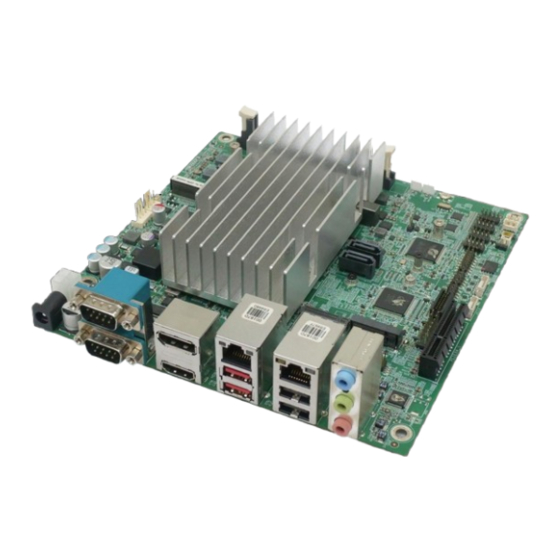
1.1 Introduction Figure 1-1: KINO-EHL2-J6412 The KINO-EHL2-J6412 is a Mini-ITX form factor single bard computer. It has an on-board 10nm Intel® Celeron® processor, and supports one DDR4 3200 SO-DIMM (up to 16GB). The KINO-EHL2-J6412 series includes one DP port and one HDMI port for dual independent display. -
Page 17: Benefits
Powerful graphics support multi-display Staying connected with wired LAN connections Speedy running of multiple programs and applications 1.3 Features The KINO-EHL2-J6412 motherboard features are listed below: Mini-ITX form factor RoHS compliant On-board 10nm Intel® Celeron® processor ... -
Page 18: Connectors
KINO-EHL2-J6412 Mini-ITX SBC 1.4 Connectors The connectors on the KINO-EHL2-J6412 are shown in the figure below. Figure 1-2: Connectors Page 4... -
Page 19: Dimensions
KINO-EHL2-J6412 Mini-ITX SBC 1.5 Dimensions The main dimensions of the KINO-EHL2-J6412 are shown in the diagram below. Figure 1-3: KINO-EHL2-J6412 Series Main Dimensions (mm) Page 5... -
Page 20: Data Flow
KINO-EHL2-J6412 Mini-ITX SBC 1.6 Data Flow Figure 1-4 shows the data flow between the system chipset, the CPU and other 852H components installed on the motherboard. Figure 1-4: Data Flow Diagram Page 6... -
Page 21: Technical Specifications
KINO-EHL2-J6412 Mini-ITX SBC 1.7 Technical Specifications The KINO-EHL2-J6412 technical specifications are listed below. 747H Specification/Model KINO-EHL2-J6412 Series Form Factor Mini-ITX Intel® Celeron® J6412 on-board SoC On-board SoC Memory 1 x 260-pin 3200 MHz DDR4 SO-DIMM (system max. 16GB) Integrated Graphics Intel®... - Page 22 KINO-EHL2-J6412 Mini-ITX SBC Specification/Model KINO-EHL2-J6412 Series Display Ports Triple independent display 1 x HDMI 1.4 (up to 4096 x 2160@30Hz) 1 x DP 1.4 (up to 4096 x 2160 @60Hz) 1 x IEI iDPM 3040 slot (only for IEI eDP/LVDS/VGA module) Ethernet LAN1: Intel®...
-
Page 23: Table 1-1: Kino-Ehl2-J6412 Series Specifications
KINO-EHL2-J6412 Mini-ITX SBC Specification/Model KINO-EHL2-J6412 Series Humidity 5%–95% (non-condensing) Physical Specifications Dimensions 170 mm x 170 mm Weight GW/NW 900 g / 400 g Table 1-1: KINO-EHL2-J6412 Series Specifications Page 9... -
Page 24: Packing List
KINO-EHL2-J6412 Mini-ITX SBC Chapter Packing List Page 10... -
Page 25: Anti-Static Precautions
Only handle the edges of the PCB: Don't touch the surface of the motherboard. Hold the motherboard by the edges when handling. 2.2 Unpacking Precautions When the KINO-EHL2-J6412 series is unpacked, please do the following: Follow the antistatic guidelines above. -
Page 26: Packing List
If any of the components listed in the checklist below are missing, do not proceed with the installation. Contact the IEI reseller or vendor the KINO-EHL2-J6412 series was purchased from or contact an IEI sales representative directly by sending an email to sales@ieiworld.com... -
Page 27: Optional Items
KINO-EHL2-J6412 Mini-ITX SBC 2.4 Optional Items The following are optional components which may be separately purchased: Item and Part Number Image USB cable, 300mm,P=2.00 (P/N : CB-USB02A-RS) SATA power cable, MOLEX 5264-4P to SATA15P (P/N: 32102-000100-200-RS) RS-232/422/485, 200mm,2*5 pin, P=2.0... -
Page 28: Connectors
KINO-EHL2-J6412 Mini-ITX SBC Chapter Connectors Page 14... -
Page 29: Peripheral Interface Connectors
KINO-EHL2-J6412 Mini-ITX SBC 3.1 Peripheral Interface Connectors This chapter details all the jumpers and connectors. 3.1.1 KINO-EHL2-J6412 Layout The figures below show all the connectors and jumpers. Figure 3-1: Connectors and Jumpers Page 15... -
Page 30: Peripheral Interface Connectors
KINO-EHL2-J6412 Mini-ITX SBC 3.1.2 Peripheral Interface Connectors The table below lists all the connectors on the board. Connector Type Label Battery connector 2-pin wafer BAT1 Buzzer connector 2-pin wafer Digital I/O connector 14-pin header DIO1 Fan connector (CPU) 4-pin wafer... -
Page 31: External Interface Panel Connectors
KINO-EHL2-J6412 Mini-ITX SBC Connector Type Label Flash SPI ROM Connector 6-pin wafer JBIOS1 Flash EC ROM Connector 8-pin header JEC2 DNX mode setting jumper 2-pin header J_DNX1 EC Debug Connector 6-pin wafer JEC1 Flash Setting Jumper 3-pin header J_FLASH1 USB 2.0 connectors... -
Page 32: Internal Peripheral Connectors
A system battery is placed in the battery holder. The battery provides power to the system clock to retain the time when power is turned off. NOTE: It is recommended to attach the RTC battery onto the system chassis in which the KINO-EHL2-J6412 is installed. Page 18... -
Page 33: Buzzer Intrusion Connector
KINO-EHL2-J6412 Mini-ITX SBC Figure 3-2: Battery Connector Location Description VBATT Table 3-3: Battery Connector Pinouts 3.2.2 Buzzer Intrusion Connector CN Label: CN Type: 2-pin header, p=1.25 mm CN Location: Figure 3-3 787H CN Pinouts: See Table 3-4 The buzzer connector is connected to a buzzer. -
Page 34: Figure 3-3: Buzzer Connector Location
KINO-EHL2-J6412 Mini-ITX SBC Figure 3-3: Buzzer Connector Location Description PC_BEEP Table 3-4: Buzzer Connector Pinouts Page 20... -
Page 35: Digital I/O Connector
KINO-EHL2-J6412 Mini-ITX SBC 3.2.3 Digital I/O Connector CN Label: DIO1 CN Type: 14-pin header, p=2.00 mm CN Location: See Figure 3-4 CN Pinouts: See Table 3-5 The digital I/O connector provides programmable input and output for external devices. Figure 3-4: Digital I/O Connector Location PIN NO. -
Page 36: Fan Connector (Cpu)
KINO-EHL2-J6412 Mini-ITX SBC 3.2.4 Fan Connector (CPU) CN Label: CPU_FAN1 CN Type: 4-pin wafer, p=2.54 mm CN Location: See Figure 3-5 CN Pinouts: See Table 3-6 The fan connector attaches to a CPU cooling fan. Figure 3-5: CPU Fan Connector Location PIN NO. -
Page 37: Fan Connector (System)
KINO-EHL2-J6412 Mini-ITX SBC 3.2.5 Fan Connector (System) CN Label: SYS_FAN2 CN Type: 3-pin wafer, p=2.54 mm CN Location: See Figure 3-6 CN Pinouts: See Table 3-7 Each fan connector attaches to a system cooling fan. Figure 3-6: System Fan Connector Location PIN NO. -
Page 38: Front Panel Connector
KINO-EHL2-J6412 Mini-ITX SBC 3.2.6 Front Panel Connector CN Label: F_PANEL1 CN Type: 14-pin header, p=2.54 mm CN Location: See Figure 3-7 CN Pinouts: See Table 3-8 The front panel connector connects to the indicator LEDs and buttons on the computer's front panel. -
Page 39: Ddr4 So-Dimm Scoket
KINO-EHL2-J6412 Mini-ITX SBC FUNCTION DESCRIPTION FUNCTION DESCRIPTION Power Button PWR_BTN+ Speaker SPKR- PWR_BTN- HDD LED HDD_LED+ Reset Button Reset+ HDD_LED- Reset- Table 3-8: Front Panel Connector Pinouts 3.2.7 DDR4 SO-DIMM Scoket CN Label: DIMM1 CN Type: DDR4 slot CN Location: See Figure 3-8 The DIMM slots is for DDR4 DIMM memory modules. -
Page 40: Pcie X4 Slot
KINO-EHL2-J6412 Mini-ITX SBC 3.2.8 PCIe x4 Slot CN Label: PCIEX4_1 CN Type: PCIe x4 slot CN Location: See Figure 3-9 The PCIe x4 interface provides x1 signal for PCIe expansion cards. Figure 3-9: PCIe x4 Slot Location 3.2.9 M.2 Slot, A-key... -
Page 41: Figure 3-10: M.2 A-Key Slot Location
KINO-EHL2-J6412 Mini-ITX SBC Figure 3-10: M.2 A-key Slot Location Description Description +V3.3A USB+ +V3.3A USB- Module Key Module Key Module Key Module Key Module Key Module Key Module Key Module Key Page 27... -
Page 42: Slot, B-Key
KINO-EHL2-J6412 Mini-ITX SBC Description Description PCIE_TX4+ PCIE_TX4- PCIE_RX4+ PCIE_RX4- CLK_M2_A+ CLK_M2_A- BTWIFI_SUS_CLK WLAN_PERST# +V3.3A_WLAN +V3.3A_WLAN +V3.3A_WLAN PEWAKE# +V3.3A +V3.3A Table 3-9: M.2 A-key Slot Pinouts 3.2.10 M.2 Slot, B-key CN Label: M2_B_KEY CN Type: M.2 B-key slot CN Location: See Figure 3-11... -
Page 43: Figure 3-11: M.2 B-Key Slot Location
KINO-EHL2-J6412 Mini-ITX SBC Figure 3-11: M.2 B-key Slot Location PIN NO. DESCRIPTION PIN NO. DESCRIPTION WWAN_CONFIG3 +3.3V_WWAN +3.3V_WWAN WWAN_FCP_OFF USB_D+ WWAN_DISABLE USB_D- Module Key Module Key Module Key Module Key Module Key Module Key Module Key Module Key PSE_I2S1_SCLK WWAN_CONFIG0... -
Page 44: Table 3-10: M.2 B-Key Slot Pinouts
KINO-EHL2-J6412 Mini-ITX SBC PCIE_RXN7 WWAN_UIM_RST PCIE_RXP7 WWAN_UIM_CLK WWAN_UIM_DAT PCIE_TXN7 UIM_PWR PCIE_TXP7 SSD_DEVSLP PCIE_RXN6 PCIE_RXP6 PCIE_TXN6 PCIE_TXP6 WWAN_PERST# CLK_M2_B_N WWAN_WAKE# CLK_M2_B_P WWAN_SIM1_DET WWAN_RST WWAN_SUSCLK DET_OS-PCIE/ +3.3V GND-SATA +3.3V +3.3V WWAN_CONFIG2 Table 3-10: M.2 B-key Slot Pinouts Page 30... -
Page 45: Idpm Slot
KINO-EHL2-J6412 Mini-ITX SBC 3.2.11 IDPM Slot CN Label: IDPM1 CN Type: M.2 B-key slot CN Location: See Figure 3-12 CN Pinouts: See Table 3-11 The iDPM slot only use for IEI eDP/LVDS/VGA module Figure 3-12: IDPM Slot Location IDPM: IEI IDPM Slot (for IEI eDP/LVDS/VGA Module) PIN NO. -
Page 46: Table 3-11: Idpm Connector Pinouts
KINO-EHL2-J6412 Mini-ITX SBC Module Key Module Key Module Key Module Key Module Key +3.3VS DISPLAY_DETECT_PIN21 +3.3VS DISPLAY_DETECT_PIN23 +3.3VS +3.3VS EDP_TX3_DN +12VS EDP_TX3_DP +12VS +12VS EDP_TX2_DN +12VS EDP_TX2_DP SMB_CLK EDP_TX1_DN SMB_DATA EDP_TX1_DP EC_BKLT_CTRL EDP_TX0_DN EDP1_BKLT_CTRL EDP_TX0_DP EDP1_BKLT_EN EDP1_VDD_EN # EDP_AUX_DN EDP_HPD_R... -
Page 47: Power Button
KINO-EHL2-J6412 Mini-ITX SBC 3.2.12 Power Button CN Label: PWR_SW1 CN Type: Push button CN Location: See Figure 3-13 The on-board power button controls system power. Figure 3-13: Power Button Location Page 33... -
Page 48: Power Connector
KINO-EHL2-J6412 Mini-ITX SBC 3.2.13 Power Connector CN Label: CN Type: 4-pin connector, p=4.2 mm CN Location: See Figure 3-14 CN Pinouts: See Table 3-12 The power input connector provides power to the system. Figure 3-14: Power Connector Location Description Description... -
Page 49: Sata 6Gb/S Drive Connector
KINO-EHL2-J6412 Mini-ITX SBC 3.2.14 SATA 6Gb/s Drive Connector CN Label: S_ATA1,S_ATA2 CN Type: 7-pin SATA drive connectors CN Location: See Figure 3-15 CN Pinouts: See Table 3-13 The SATA drive connector can be connected to SATA drives. Figure 3-15: SATA 6Gb/s Drive Connector Location... -
Page 50: Sata Power Connector
KINO-EHL2-J6412 Mini-ITX SBC Description Table 3-13: SATA 3Gb/s Drive Connector Pinouts 3.2.15 SATA Power Connector CN Label: SATA_PWR1,SATA_PWR2 CN Type: 2-pin wafer, p=2.00 mm CN Location: See Figure 3-16 CN Pinouts: See Table 3-14 Use the SATA Power Connector to connect to SATA device power connections. -
Page 51: Serial Port Connector, Rs-232
KINO-EHL2-J6412 Mini-ITX SBC Description Table 3-14: SATA Power Connector Pinouts 3.2.16 Serial Port Connector, RS-232 CN Label: COM3, COM4 CN Type: 10-pin header p=2.00 mm CN Location: See Figure 3-17 CN Pinouts: See Table 3-15 Used for RS-23 communications. Figure 3-17: RS-232 Connector Location PIN NO. -
Page 52: Serial Port, Rs-232/422/485
KINO-EHL2-J6412 Mini-ITX SBC PIN NO. DESCRIPTION PIN NO. DESCRIPTION Table 3-15:RS-232 Connector Pinouts 3.2.17 Serial port, RS-232/422/485 CN Label: COM5, COM6 CN Type: 10-pin header p=2.00 mm CN Location: See Figure 3-18 CN Pinouts: See Table 3-16 Figure 3-18 RS-232/422/485 Connector Location Used for RS-232/422/485 communications. -
Page 53: Smbus Connector
KINO-EHL2-J6412 Mini-ITX SBC RS-232 RS-422 RS-485 RXD422+ RXD422- Table 3-16 RS-232/422/485 Connector Pinouts RS-232 Pinouts RS-422 Pinouts RS-485 Pinouts Table 3-17 RS-232/422/485 Pinouts of D-sub 9 Connector 3.2.18 SMBus Connector CN Label: SMB1 CN Type: 4-pin wafer, p=1.25 mm CN Location:... -
Page 54: I2C Connector
KINO-EHL2-J6412 Mini-ITX SBC Figure 3-19: SMBus Connector Location DESCRIPTION SMB_DATA SMB_CLK +5 V Table 3-18: SMBus Connector Pinouts 3.2.19 I2C Connector CN Label: I2C1 CN Type: 4-pin wafer, p=1.25 mm CN Location: See Figure 3-20 CN Pinouts: See Table 3-19... -
Page 55: Flash Descriptor Override Setting Jumper
KINO-EHL2-J6412 Mini-ITX SBC Figure 3-20: I2C Connector Location Description I2C_DATA I2C_CLK Table 3-19: I2C Connector Pinouts 3.2.20 Flash Descriptor Override Setting Jumper CN Label: J_FLASH1 CN Type: 2-pin header, p=2.00 mm CN Location: See Figure 3-21 CN Pinouts: See Table 3-20... -
Page 56: Flash Ec Rom Connector
KINO-EHL2-J6412 Mini-ITX SBC Figure 3-21 Flash Setting Jumper Connector Locatio PIN NO. DESCRIPTION Short 1-2 Disable(default) Short 2-3 Enable Table 3-20 Flash Setting Jumper Connector Pinouts 3.2.21 Flash EC ROM Connector CN Label: JEC2 CN Type: 8-pin header, p=1.27 mm... -
Page 57: Dnx Mode Setting Jumper
KINO-EHL2-J6412 Mini-ITX SBC Figure 3-22: Flash EC ROM Connector Location PIN NO. DESCRIPTION PIN NO. DESCRIPTION SPI_CS# +3.3V SPI_SO EC_DET_FLASH SPI_CLK SPI_SI Table 3-21: Flash EC ROM Connector Pinouts 3.2.22 DNX mode setting jumper CN Label: J_DNX1 CN Type: 2-pin header, p=1.27 mm... -
Page 58: Ec Debug Connector
KINO-EHL2-J6412 Mini-ITX SBC Figure 3-23 DNX mode setting jumper Connector Location PIN NO. DESCRIPTION Open Normal(default) Short Enable DNX Boot Table 3-22 DNX Mode Setting Jumper Connector Ponout 3.2.23 EC Debug Connector CN Label: JEC1 CN Type: 6-pin wafer, p=1.25 mm... -
Page 59: Usb 2.0 Connectors
KINO-EHL2-J6412 Mini-ITX SBC Figure 3-24: EC Debug Connector Location PIN NO. DESCRIPTION PIN NO. DESCRIPTION EDICLK EDICS EDIDI EDIDO Table 3-23: EC Debug Connector Pinouts 3.2.24 USB 2.0 Connectors CN Label: JUSB3, JUSB4 CN Type: 8-pin header, p=2.00 mm CN Location:... -
Page 60: Clear Cmos Button
KINO-EHL2-J6412 Mini-ITX SBC The USB 2.0 connector connects to USB 2.0 devices. Each pin header provides two USB 2.0 ports. Figure 3-25: USB 2.0 Connector Locations PIN NO. DESCRIPTION PIN NO. DESCRIPTION USB_DATA- USB_DATA+ USB_DATA+ USB_DATA- Table 3-24: USB 2.0 Connector Pinouts 3.2.25 Clear CMOS Button... -
Page 61: At/Atx Power Mode Setting Switch
KINO-EHL2-J6412 Mini-ITX SBC CN Location: See Figure 3-26 CN Pinouts: See Table 3-25 Figure 3-26 Clear CMOS Button Location PIN NO. DESCRIPTION Keep CMOS Setup NC(default) (Mormal Operation) Press button Clear CMOS Setup Table 3-25 Clear CMOS Button Pinout 3.2.26 AT/ATX power mode setting switch... -
Page 62: Chassis Intrusion Connector
KINO-EHL2-J6412 Mini-ITX SBC CN Location: See Figure 3-27 CN Pinouts: See Table 3-26 Figure 3-27 AT/ATX power mode setting Location PIN NO. DESCRIPTION Short A-B ATX Power Mode(default) Short B-C AT Power Mode Table 3-26 AT/AYX Power Mode Setting Switch Pinout 3.2.27 Chassis intrusion connector... -
Page 63: Figure 3-28 Chassis Intrusion Connector Location
KINO-EHL2-J6412 Mini-ITX SBC Figure 3-28 Chassis Intrusion Connector Location PIN NO. DESCRIPTION -CASEOPEN Table 3-27 Chassis Intrusion Connector Connector Pinout Page 49... -
Page 64: Sim Card Slot
KINO-EHL2-J6412 Mini-ITX SBC 3.2.28 SIM Card Slot CN Label: SIM1 CN Type: 7-pin SIM holder CN Location: See Figure 3-29 CN Pinouts: See Table 3-28 Figure 3-29 SIM Card Slot Location PIN NO. DESCRIPTION SIM_VCC SIM_RST SIM_Clock SIM_DATA Table 3-28 SIM Card Slot Pinouts... -
Page 65: External Peripheral Interface Connector Panel
KINO-EHL2-J6412 Mini-ITX SBC 3.3 External Peripheral Interface Connector Panel The figure below shows the external peripheral interface connector (EPIC) panel. The EPIC panel consists of the following: Figure 3-30: External Peripheral Interface Connector 3.3.1 Ethernet and USB 2.0 Combo Connector... -
Page 66: Ethernet And Usb 3.2 Gen 2 Combo Connector
KINO-EHL2-J6412 Mini-ITX SBC Figure 3-31: Ethernet Connector Description Description on: linked off: 100 Mb/s blinking: data is being sent/received green: 1000 Mb/s orange: 2500 Mb/s Table 3-30: Connector LEDs The USB 2.0 connector can be connected to a USB 2.0 device. -
Page 67: Figure 3-32: Ethernet Connector
KINO-EHL2-J6412 Mini-ITX SBC Description Description LAN1_MDI0N LAN1_MDI2N LAN1_MDI1P LAN1_MDI3P LAN1_MDI1N LAN1_MDI3N Table 3-32: LAN1 Ethernet Connector Pinouts Figure 3-32: Ethernet Connector Description Description on: linked off: 100 Mb/s blinking: data is being sent/received green: 1000 Mb/s orange: 2500 Mb/s Table 3-33: Connector LEDs The USB 3.2 Gen 2 (10Gb/s) connector can be connected to a USB device. -
Page 68: Serial Port Connectors (Com1 And Com2)
KINO-EHL2-J6412 Mini-ITX SBC 3.3.3 Serial Port Connectors (COM1 and COM2) CN Label: COM1 CN Type: D-sub 9 CN Location: See Figure 3-30 CN Pinouts: See Table 3-35 and Figure 3-33 The serial port connects to a RS-232 serial communications device. -
Page 69: Hdmi And Dp Connector
KINO-EHL2-J6412 Mini-ITX SBC CN Pinouts: See Figure 3-34 The connector supports the 28V power adapter. Figure 3-34: Power Connector (4-pin DIN) 3.3.5 HDMI and DP Connector CN Label: HDMI_DP1 CN Type: HDMI and DP connector CN Location: See Figure 3-30... -
Page 70: Figure 3-35: Dp Connector Pinout Locations
KINO-EHL2-J6412 Mini-ITX SBC PIN NO. DESCRIPTION PIN NO. DESCRIPTION HDMI2_DATA2 HDMI2_DATA2# HDMI2_DATA1 HDMI2_DATA1# HDMI2_DATA0 HDMI2_DATA0# HDMI2_CLK HDMI2_CLK# HDMI2_SCL HDM2I_SDA HDMI2_HPD Table 3-36: HDMI and DP Connector Pinouts Figure 3-35: DP Connector Pinout Locations Figure 3-36: HDMI Connector Pinout Locations Page 56... -
Page 71: External Audio Jack
KINO-EHL2-J6412 Mini-ITX SBC 3.3.6 External audio jack CN Label: AUDIO_CV1 CN Type: Audio jack CN Location: See Figure 3-30 The audio jacks connect to external audio devices. Line In port (Light Blue): Connects a CD-ROM, DVD player, or other audio devices. -
Page 72: Installation
KINO-EHL2-J6412 Mini-ITX SBC Chapter Installation Page 58... -
Page 73: Anti-Static Precautions
KINO-EHL2-J6412 and severe injury to the user. Electrostatic discharge (ESD) can cause serious damage to electronic components, including the KINO-EHL2-J6412. Dry climates are especially susceptible to ESD. It is therefore critical that whenever the KINO-EHL2-J6412 or any other electrical component is handled, the following anti-static precautions are strictly adhered to. - Page 74 This helps to prevent potential ESD damage. Turn all power to the KINO-EHL2-J6412 off: When working with the KINO-EHL2-J6412, make sure that it is disconnected from all power supplies and that no electricity is being fed into the system.
-
Page 75: Module Installation
KINO-EHL2-J6412 Mini-ITX SBC 4.3 M.2 Module Installation The KINO-EHL provide two ways to install the M.2 expansion card. One is using screw, and the other is using the retainer. Please follow the steps below. Mode One: Using screw Step 1: Locate the M.2 module slot. -
Page 76: System Configuration
KINO-EHL2-J6412 Mini-ITX SBC 4.4 System Configuration The KINO-EHL2-J6412 is a jumperless single board computer. The system configuration is controlled by buttons and switches. The system configuration must be performed before installation. 4.4.1 AT/ATX Power Mode Setting The AT and ATX power mode selection is made through the AT/ATX power mode switch which is shown in Figure 4-3. -
Page 77: Dnx Mode Setting Jumper
KINO-EHL2-J6412 Mini-ITX SBC 4.4.2 DNX Mode Setting Jumper Figure 4-4 DNX Mode Setting Locations Setting DESCRIPTION Open Normal (default) Short Enable DNX Boot Table 4-1 DNX Mode Jumper Settings 4.4.3 Clear CMOS Button To reset the BIOS, remove the on-board battery and press the clear CMOS button for three seconds or more. -
Page 78: Flash Descriptor Security Override
KINO-EHL2-J6412 Mini-ITX SBC Figure 4-5: Clear CMOS Button Location 4.4.4 Flash Descriptor Security Override The Flash Descriptor Security Override jumper (J_FLASH1) specifies whether to override the flash descriptor. Setting Description Short 1-2 Disable (default) Short 2-3 Enable Table 4-2: Flash Descriptor Security Override Jumper Settings... -
Page 79: Internal Peripheral Device Connections
This section outlines the installation of peripheral devices to the on-board connectors. 4.5.1 SATA Drive Connection The KINO-EHL2-J6412 is shipped with one SATA drive cable. To connect the SATA drive to the connector, please follow the steps below. Step 1: Locate the SATA connector and the SATA power connector. -
Page 80: Usb Cable Connection
KINO-EHL2-J6412 Mini-ITX SBC Figure 4-7: SATA Drive Cable Connection Step 3: Connect the cable to the SATA disk. Connect the connector on the other end of the cable to the connector at the back of the SATA drive. See Figure 4-7. -
Page 81: Figure 4-11: Dual Usb Cable Connection
If the USB pins are not properly aligned, the USB device can burn out. Step 2: Align the connectors. The cable has two connectors. Correctly align pin 1on each cable connector with pin 1 on the KINO-EHL2-J6412 USB connector. Step 3: Insert the cable connectors. -
Page 82: Driver Download
KINO-EHL2-J6412 Mini-ITX SBC 4.6 Driver Download To download drivers from IEI Resource Download Center, follow the steps below. Step 1: Go to https://download.ieiworld.com. Type KINO-EHL2-J6412 and press Enter. Step 2: All product-related software, utilities, and documentation will be listed. You can choose Driver to filter the result. - Page 83 KINO-EHL2-J6412 Mini-ITX SBC NOTE: To install software from the downloaded ISO image file in Windows 8, 8.1 or 10, double-click the ISO file to mount it as a virtual drive to view its content. On Windows 7 system, an additional tool (such as Virtual CD-ROM Control Panel from Microsoft) is needed to mount the file.
-
Page 84: Bios
KINO-EHL2-J6412 Mini-ITX SBC Chapter BIOS Page 70... -
Page 85: Introduction
KINO-EHL2-J6412 Mini-ITX SBC 5.1 Introduction The BIOS is programmed onto the BIOS chip. The BIOS setup program allows changes to certain system settings. This chapter outlines the options that can be changed. NOTE: Some of the BIOS options may vary throughout the life cycle of the product and are subject to change without prior notice. -
Page 86: Using Setup
KINO-EHL2-J6412 Mini-ITX SBC 5.1.2 Using Setup The BIOS Setup menu can be navigated by using a keyboard or a touchscreen. 5.1.2.1 Keyboard Navigation For keyboard navigation, use the navigation keys shown in Table 5-1. Function Up arrow Move to previous item... -
Page 87: Touch Navigation
KINO-EHL2-J6412 Mini-ITX SBC 5.1.2.2 Touch Navigation For touchscreen navigation, use the on-screen navigation keys shown below. On-screen Button Function Previous Values Load the last value you set. Optimized Defaults Load the factory default values in order to achieve the best performance. -
Page 88: Getting Help
KINO-EHL2-J6412 Mini-ITX SBC 5.1.3 Getting Help When F1 is pressed a small help window describing the appropriate keys to use and the possible selections for the highlighted item appears. To exit the Help Window, press the key. 5.1.4 Unable to Reboot after Configuration Changes If the computer cannot boot after changes to the system configuration is made, CMOS defaults. -
Page 89: Main
KINO-EHL2-J6412 Mini-ITX SBC 5.2 Main The Main BIOS menu (BIOS Menu 1 & BIOS Menu 2) appears when the BIOS Setup program is entered. The Main menu gives an overview of the basic system information. BIOS Menu 1: Main (1/2) - Page 90 KINO-EHL2-J6412 Mini-ITX SBC BIOS Information The BIOS Information lists a brief summary of the BIOS. The fields in BIOS Information cannot be changed. The items shown in the system overview include: BIOS Vendor: Installed BIOS vendor Core Version: Current BIOS version ...
- Page 91 KINO-EHL2-J6412 Mini-ITX SBC The System Overview field also has two user configurable fields: System Date [xx/xx/xx] Use the System Date option to set the system date. Manually enter the day, month and year. System Time [xx:xx:xx] Use the System Time option to set the system time. Manually enter the hours, minutes and seconds.
-
Page 92: Advanced
KINO-EHL2-J6412 Mini-ITX SBC 5.3 Advanced Use the Advanced menu (BIOS Menu 3 ) to configure the CPU and peripheral devices through the following sub-menus: WARNING! Setting the wrong values in the sections below may cause the system to malfunction. Make sure that the settings made are compatible with the hardware. -
Page 93: Cpu Configuration
KINO-EHL2-J6412 Mini-ITX SBC 5.3.1 CPU Configuration Use the CPU Configuration menu (BIOS Menu 4 & BIOS Menu 5 & BIOS Menu 6) to view detailed CPU specifications or enable the Intel Virtualization Technology. BIOS Menu 4: CPU Configuration (1/3) Page 79... - Page 94 KINO-EHL2-J6412 Mini-ITX SBC BIOS Menu 5: CPU Configuration (2/3) BIOS Menu 6: CPU Configuration (3/3) Page 80...
- Page 95 KINO-EHL2-J6412 Mini-ITX SBC Intel (VMX) Virtualization Technology [Enabled] Use the Intel (VMX) Virtualization Technology option to enable or disable virtualization on the system. When combined with third party software, Intel® Virtualization technology allows several OSs to run on the same system at the same time.
- Page 96 KINO-EHL2-J6412 Mini-ITX SBC Tcc Activation Offset Use the Tcc Activation option to set Tcc activation temprature at which the Thermal Control Circuit must be activated.Tcc will be activated at: Tcc Activation Temp-Tcc Activation Offset. Tcc Activation Offset range is 0 to 63.
-
Page 97: Trusted Computing
KINO-EHL2-J6412 Mini-ITX SBC 5.3.2 Trusted Computing Use the Trusted Computing menu (BIOS Menu 7) to configure settings related to the Trusted Computing Group (TCG) Trusted Platform Module (TPM). BIOS Menu 7: PCH-FW Configuration TPM Support [Enable] Use the TPM Support option to configure support for the TPM. -
Page 98: Rtc Wake Settings
KINO-EHL2-J6412 Mini-ITX SBC 5.3.3 RTC Wake Settings The RTC Wake Settings menu (BIOS Menu 8) configures RTC wake event. BIOS Menu 8: RTC Wake Settings Wake system with Fixed Time [Disabled] Use the Wake system with Fixed Time option to enable or disable the system wake on alarm event. -
Page 99: F81966 Super Io Configuration
KINO-EHL2-J6412 Mini-ITX SBC Wake up second After setting the alarm, the computer turns itself on from a suspend state when the alarm goes off. 5.3.4 F81966 Super IO Configuration Use the F81966 Super IO Configuration menu (BIOS Menu 9) to set or change the configurations for the serial ports. -
Page 100: Serial Port 1 Configuration
KINO-EHL2-J6412 Mini-ITX SBC 5.3.4.1 Serial Port 1 Configuration Use the Serial Port 1 Configuration menu (BIOS Menu 10) to configure the serial port 1. BIOS Menu 10: Serial Port 1 Configuration Menu Serial Port [Enabled] Use the Serial Port option to enable or disable the serial port. -
Page 101: Serial Port 2 Configuration
KINO-EHL2-J6412 Mini-ITX SBC 5.3.4.2 Serial Port 2 Configuration Use the Serial Port 2 Configuration menu (BIOS Menu 11) to configure the serial port 2. BIOS Menu 11: Serial Port 2 Configuration Menu Serial Port [Enabled] Use the Serial Port option to enable or disable the serial port. -
Page 102: Serial Port 3 Configuration
KINO-EHL2-J6412 Mini-ITX SBC 5.3.4.3 Serial Port 3 Configuration Use the Serial Port 3 Configuration menu (BIOS Menu 12) to configure the serial port 3. BIOS Menu 12: Serial Port 3 Configuration Menu Serial Port [Enabled] Use the Serial Port option to enable or disable the serial port. -
Page 103: Serial Port 4 Configuration
KINO-EHL2-J6412 Mini-ITX SBC 5.3.4.4 Serial Port 4 Configuration Use the Serial Port 4 Configuration menu (BIOS Menu 13) to configure the serial port 4. BIOS Menu 13: Serial Port 4 Configuration Menu Serial Port [Enabled] Use the Serial Port option to enable or disable the serial port. -
Page 104: Serial Port 5 Configuration
KINO-EHL2-J6412 Mini-ITX SBC 5.3.4.5 Serial Port 5 Configuration Use the Serial Port 5 Configuration menu (BIOS Menu 14) to configure the serial port 5. BIOS Menu 14: Serial Port 5 Configuration Menu Serial Port [Enabled] Use the Serial Port option to enable or disable the serial port. -
Page 105: Serial Port 6 Configuration
KINO-EHL2-J6412 Mini-ITX SBC 5.3.4.6 Serial Port 6 Configuration Use the Serial Port 6 Configuration menu (BIOS Menu 15) to configure the serial port 6. BIOS Menu 15: Serial Port 6 Configuration Menu Serial Port [Enabled] Use the Serial Port option to enable or disable the serial port. - Page 106 KINO-EHL2-J6412 Mini-ITX SBC The ENE KB9068 Monitor menu (BIOS Menu 16) contains the smart fan mode configuration submenu and shows the state of H/W real-time operating temperature, fan speeds and system voltages. BIOS Menu 16: ENE KB9068 Monitor PC Health Status The following system parameters and values are shown.
-
Page 107: Smart Fan Mode Configuration
KINO-EHL2-J6412 Mini-ITX SBC CPU_CORE1 +12V +5VSB +3.3VSB 5.3.5.1 Smart Fan Mode Configuration Use the Smart Fan Mode Configuration submenu (BIOS Menu 17) to configure the CPU/system fan start/off temperature and control mode. BIOS Menu 17: Smart Fan Mode Configuration ... -
Page 108: Serial Port Console Redirection
KINO-EHL2-J6412 Mini-ITX SBC Manual Mode PWM CPU_FAN1 will start work according to this fixed PWM. SYS_FAN2 Smart Fan Control [Auto Mode] Use the SYS_FAN2 Smart Fan Control option to configure the System Smart Fan. Manual Mode The fan spins at the speed set in Manual Mode settings. - Page 109 KINO-EHL2-J6412 Mini-ITX SBC BIOS Menu 18: Serial Port Console Redirection (1/2) Page 95...
-
Page 110: Console Redirection Settings
KINO-EHL2-J6412 Mini-ITX SBC BIOS Menu 19: Serial Port Console Redirection (2/2) Console Redirection [Disabled] Use Console Redirection option to enable or disable the console redirection function. Disabled Disabled the console redirection function EFAULT Enabled Enabled the console redirection function The Console Redirection Settings submenu will be available when the Console Redirection option is enabled. - Page 111 KINO-EHL2-J6412 Mini-ITX SBC BIOS Menu 20: COM Console Redirection Settings Terminal Type [ANSI] Use the Terminal Type option to specify the remote terminal type. VT100 The target terminal type is VT100 VT100+ The target terminal type is VT100+ ...
- Page 112 KINO-EHL2-J6412 Mini-ITX SBC Sets the serial port transmission speed at 19200. 19200 38400 Sets the serial port transmission speed at 38400. 57600 Sets the serial port transmission speed at 57600. 115200 Sets the serial port transmission speed at 115200.
-
Page 113: Nvme Configuration
KINO-EHL2-J6412 Mini-ITX SBC 5.3.7 NVMe Configuration Use the NVMe Configuration (BIOS Menu 21) menu to display the NVMe controller and device information. BIOS Menu 21: NVMe Configuration Page 99... -
Page 114: Chipset
KINO-EHL2-J6412 Mini-ITX SBC 5.4 Chipset Use the Chipset menu (BIOS Menu 22) to access the PCH IO and System Agent (SA) configuration menus. WARNING! Setting the wrong values for the Chipset BIOS selections in the Chipset BIOS menu may cause the system to malfunction. -
Page 115: System Agent (Sa) Configuration
KINO-EHL2-J6412 Mini-ITX SBC 5.4.1 System Agent (SA) Configuration Use the System Agent (SA) Configuration menu (BIOS Menu 23) to configure the System Agent (SA) parameters. BIOS Menu 23: System Agent (SA) Configuration VT-d [Enabled] Use the VT-d option to enable or disable the VT-d capability. -
Page 116: Memory Configuration
KINO-EHL2-J6412 Mini-ITX SBC 5.4.1.1 Memory Configuration Use the Memory Configuration submenu (BIOS Menu 24) to view memory information. BIOS Menu 24: Memory Configuration Page 102... -
Page 117: Graphics Configuration
KINO-EHL2-J6412 Mini-ITX SBC 5.4.1.2 Graphics Configuration Use the Graphics Configuration (BIOS Menu 25) menu to configure the video device connected to the system. BIOS Menu 25: Graphics Configuration Primary Display [Auto] Use the Primary Display option to select the primary graphics controller the system uses. - Page 118 KINO-EHL2-J6412 Mini-ITX SBC Graphics option should be set to Enabled and the above Primary Display option should be set to IGFX. Auto Auto mode Disabled Disables IGFX. Enables IGFX. Enabled Default DVMT Pre-Allocated [160M] Use the DVMT Pre-Allocated option to set the amount of system memory allocated to the integrated graphics processor when the system boots.
- Page 119 KINO-EHL2-J6412 Mini-ITX SBC LCD Control iDPM Slot Control[Auto Detect Module(EDP/LVDS/VGA)] Use the iDPM Slot Control option to select iDPM module or auto detect for iDPM LVDS/EDP/VGA Module. Auto Detect Auto detect for iDPM LVDS/EDP/VGA Module. EFAULT Module(EDP /LVDS/VGA) ...
-
Page 120: Pch-Io Configuration
KINO-EHL2-J6412 Mini-ITX SBC LVDS Backlight PWM mode[Invert] Invert Select Invert LVDS Backlight. EFAULT Normal Select normol LVDS Backlight. 5.4.2 PCH-IO Configuration Use the PCH-IO Configuration menu (BIOS Menu 26) to configure the PCH parameters. BIOS Menu 26: PCH-IO Configuration ... -
Page 121: Table 5-3: Bios Options And Configured Usb Ports
KINO-EHL2-J6412 Mini-ITX SBC Power Saving Function(EUP) [Disabled] Use the Power Saving Function(EUP) BIOS option to enable or disable the power saving function. Disabled Power saving function is disabled. EFAULT Enabled Power saving function is enabled. It will reduce power consumption when the system is off. -
Page 122: Pci Express Configuration
KINO-EHL2-J6412 Mini-ITX SBC 5.4.2.1 PCI Express Configuration Use the PCI Express Configuration submenu (BIOS Menu 27) to configure the PCI Express slots. BIOS Menu 27: PCI Express Configuration 5.4.2.1.1 PCIe Root Port Setting Use the PCIEX4_1, M2_B_KEY Slot, M2_A_KEY Slot, submenu (BIOS Menu 28) to configure the PCI Root Port Setting. - Page 123 KINO-EHL2-J6412 Mini-ITX SBC BIOS Menu 28: PCIe Slot Configuration Submenu PCIe Speed [Auto] Use the PCIe Speed option to specify the PCI Express port speed. Configuration options are listed below. Auto Auto mode. EFAULT Gen1 Configure PCIe Speed to Gen1.
-
Page 124: M2_B_Key Slot
KINO-EHL2-J6412 Mini-ITX SBC Do not detect if a non-compliance PCI Express Disabled EFAULT device is connected to the PCI Express port. Enabled Detect if a non-compliance PCI Express device is connected to the PCI Express port. 5.4.2.1.2 M2_B_KEY Slot ... -
Page 125: M2_A_Key Slot
KINO-EHL2-J6412 Mini-ITX SBC Detect Non-Compliance Device [Disabled] Use the Detect Non-Compliance Device option to configure whether to detect if a non-compliance PCI Express device is connected to the PCI Express port. Do not detect if a non-compliance PCI Express... - Page 126 KINO-EHL2-J6412 Mini-ITX SBC Configure PCIe Speed to Gen1. Gen1 Gen2 Configure PCIe Speed to Gen2. Gen3 Configure PCIe Speed to Gen3. Detect Non-Compliance Device [Disabled] Use the Detect Non-Compliance Device option to configure whether to detect if a non-compliance PCI Express device is connected to the PCI Express port.
-
Page 127: Sata Configuration
KINO-EHL2-J6412 Mini-ITX SBC 5.4.2.2 SATA Configuration Use the SATA Configuration menu (BIOS Menu 29) to change and/or set the configuration of the SATA devices installed in the system. BIOS Menu 29: SATA Configuration SATA Controller(s) [Enabled] Use the SATA Controller(s) option to configure the SATA controller(s). - Page 128 KINO-EHL2-J6412 Mini-ITX SBC Configures SATA devices to the Intel RST Premium With Intel RST Premium With Intel Optane Intel Optane System Acceleration mode. System Acceleration Hot Plug [Disabled] Use the Hot Plug option (for S_ATA1) to designate the correspondent port as hot-pluggable.
-
Page 129: Hd Audio Configuration
KINO-EHL2-J6412 Mini-ITX SBC 5.4.2.3 HD Audio Configuration Use the HD Audio Configuration menu (BIOS Menu 30) to configure the PCH Azalia settings. BIOS Menu 30: HD Audio Configuration HD Audio [Auto] Use the HD Audio option to enable or disable the High Definition Audio controller. -
Page 130: Security
KINO-EHL2-J6412 Mini-ITX SBC 5.5 Security Use the Security menu (BIOS Menu 31) to set system and user passwords. BIOS Menu 31: Security Administrator Password Use the Administrator Password to set or change a administrator password. User Password Use the User Password to set or change a user password. -
Page 131: Boot
KINO-EHL2-J6412 Mini-ITX SBC 5.6 Boot Use the Boot menu (BIOS Menu 32) to configure system boot options. BIOS Menu 32: Boot 5.6.1 Boot Configuration Quiet Boot [Enabled] Use the Quiet Boot BIOS option to select the screen display when the system boots. -
Page 132: Boot Option Priorities
KINO-EHL2-J6412 Mini-ITX SBC Load PXE Option ROMs. Enabled 5.6.2 Boot Option Priorities Use the Boot Option # N to choose the system boots from the peripherals you selected The following Boot Options are listed as an example. Boot Option #1 Sets the system boot order ADATA SP580 as the first priority. -
Page 133: Save & Exit
KINO-EHL2-J6412 Mini-ITX SBC 5.7 Save & Exit Use the Save & Exit menu (BIOS Menu 33) to load default BIOS values, optimal failsafe values and to save configuration changes. BIOS Menu 33: Save & Exit Save Changes and Reset Use the Save Changes and Reset option to save the changes made to the BIOS options and reset the system. - Page 134 KINO-EHL2-J6412 Mini-ITX SBC Restore Defaults Use the Restore Defaults option to load the optimal default values for each of the parameters on the Setup menus. F3 key can be used for this operation. Save as User Defaults Use the Save as User Defaults option to save the changes done so far as user defaults.
-
Page 135: A Regulatory Compliance
KINO-EHL2-J6412 Mini-ITX SBC Appendix Regulatory Compliance Page 121... - Page 136 KINO-EHL2-J6412 Mini-ITX SBC DECLARATION OF CONFORMITY This equipment has been tested and found to comply with specifications for CE marking. If the user modifies and/or installs other devices in the equipment, the CE conformity declaration may no longer apply. FCC WARNING This equipment complies with Part 15 of the FCC Rules.
-
Page 137: B Product Disposal
KINO-EHL2-J6412 Mini-ITX SBC Appendix Product Disposal Page 123... - Page 138 KINO-EHL2-J6412 Mini-ITX SBC CAUTION: Risk of explosion if battery is replaced by an incorrect type. Only certified engineers should replace the on-board battery. Dispose of used batteries according to instructions and local regulations. Outside the European Union–If you wish to dispose of used electrical and electronic products outside the European Union, please contact your local authority so as to comply with the correct disposal method.
-
Page 139: Cbios Options
KINO-EHL2-J6412 Mini-ITX SBC Appendix BIOS Options Page 125... - Page 140 KINO-EHL2-J6412 Mini-ITX SBC Below is a list of BIOS configuration options in the BIOS chapter. BIOS Information .........................76 Compute Die Information ....................76 PCH Information ........................76 System Date [xx/xx/xx] ......................77 System Time [xx:xx:xx] .......................77 Intel (VMX) Virtualization Technology [Enabled] ..............81 ...
- Page 141 KINO-EHL2-J6412 Mini-ITX SBC SYS_FAN2 Start Temperature ....................94 SYS_FAN2 Off Temperature ....................94 SYS_FAN2 Start PWM ......................94 Console Redirection [Disabled]..................96 Terminal Type [ANSI] ......................97 Bits per second [115200] .....................97 Data Bits [8] ..........................98 Parity [None] .........................98 ...
- Page 142 KINO-EHL2-J6412 Mini-ITX SBC Boot Option #1 ........................118 Boot Option #2 ........................118 Save Changes and Reset ....................119 Discard Changes and Reset .....................119 Restore Defaults ........................120 Save as User Defaults .......................120 Restore User Defaults .......................120...
-
Page 143: D Watchdog Timer
KINO-EHL2-J6412 Mini-ITX SBC Appendix Watchdog Timer Page 129... - Page 144 KINO-EHL2-J6412 Mini-ITX SBC NOTE: The following discussion applies to DOS environment. Contact IEI support or visit the IEI website for specific drivers for other operating systems. The Watchdog Timer is provided to ensure that standalone systems can always recover from catastrophic conditions that cause the CPU to crash. This condition may have occurred by external EMIs or a software bug.
- Page 145 KINO-EHL2-J6412 Mini-ITX SBC NOTE: When exiting a program it is necessary to disable the Watchdog Timer, otherwise the system resets. EXAMPLE PROGRAM: ; INITIAL TIMER PERIOD COUNTER W_LOOP: AX, 6F02H ;setting the time-out value BL, 30 ;time-out value is 48 seconds ;...
-
Page 146: E Error Beep Code
KINO-EHL2-J6412 Mini-ITX SBC Appendix Error Beep Code Page 132... -
Page 147: Pei Beep Codes
KINO-EHL2-J6412 Mini-ITX SBC E.1 PEI Beep Codes Number of Beeps Description Memory not Installed Memory was installed twice (InstallPeiMemory routine in PEI Core called twice) Recovery started DXEIPL was not found DXE Core Firmware Volume was not found Recovery failed... -
Page 148: F Hazardous Materials Disclosure
KINO-EHL2-J6412 Mini-ITX SBC Appendix Hazardous Materials Disclosure Page 134... -
Page 149: Rohs Ii Directive (2015/863/Eu)
KINO-EHL2-J6412 Mini-ITX SBC F.1 RoHS II Directive (2015/863/EU) The details provided in this appendix are to ensure that the product is compliant with the RoHS II Directive (2015/863/EU). The table below acknowledges the presences of small quantities of certain substances in the product, and is applicable to RoHS II Directive (2015/863/EU). -
Page 150: China Rohs
KINO-EHL2-J6412 Mini-ITX SBC F.2 China RoHS 此附件旨在确保本产品符合中国 RoHS 标准。以下表格标示此产品中某有毒物质的含量符 合中国 RoHS 标准规定的限量要求。 本产品上会附有”环境友好使用期限”的标签,此期限是估算这些物质”不会有泄漏或突变”的 年限。本产品可能包含有较短的环境友好使用期限的可替换元件,像是电池或灯管,这些元 件将会单独标示出来。 部件名称 有毒有害物质或元素 壳体 印刷电路板 金属螺帽 电缆组装 风扇组装 电力供应组装 电池 O: 表示该有毒有害物质在该部件所有物质材料中的含量均在 SJ/T11364-2014 與 GB/T26572-2011 标准规定的限量要求以下。 X: 表示该有毒有害物质至少在该部件的某一均质材料中的含量超出 SJ/T11364-2014 與 GB/T26572-2011 标准规定的限量要求。 Page 136...
Need help?
Do you have a question about the KINO-EHL2 and is the answer not in the manual?
Questions and answers