Table of Contents
Advertisement
Quick Links
Mini-ITX SBC supports 6th Intel® Core™ Mobile CPU, HDMI 2.0,
M.2, SATA 6Gb/s, dual Intel® GbE, USB 3.0, PCIe Mini,
Quick Installation Guide
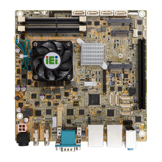
KINO-DQM170 package includes the following items:
1 x 1 x KINO-DQM170 motherboard
1 x I/O shielding
2 x SATA cable
1 x One Key Recovery CD
1 x Utility CD
1 x QIG (Quick Installation Guide)
HD Audio and RoHS
KINO-DQM170
Version 1.0
Sep 3, 2016.
Package List
©2016 Copyright by IEI Integration corp.
All rights reserved.
1
Advertisement
Chapters
Table of Contents

Subscribe to Our Youtube Channel
Related Manuals for IEI Technology KINO-DQM170


Summary of Contents for IEI Technology KINO-DQM170
- Page 1 M.2, SATA 6Gb/s, dual Intel® GbE, USB 3.0, PCIe Mini, HD Audio and RoHS KINO-DQM170 Quick Installation Guide Version 1.0 Sep 3, 2016. Package List KINO-DQM170 package includes the following items: 1 x 1 x KINO-DQM170 motherboard 1 x I/O shielding 2 x SATA cable ...
- Page 2 Specifications CPU: 6th generation Intel® Core™ mobile processor Intel® Core™ i7-6820EQ (3.5GHz, quad-core, 8M cache, TDP=45W) Intel® Core™ i5-6440EQ (3.4GHz, quad-core, 6M cache, TDP=45W) Intel® Core™ i3-6102E (1.90 GHz, dual core, 3M Cache, 25W) Intel® Celeron® G3902E (1.60 GHz, dual core, 2M Cache, 25W) ...
- Page 3 1 x KB/MS (1x 6 pin, P=2.00) 2 x RS-232/422/485 (1x9 pin, P=1.25) 3 x RS-232 (1x9 pin, P=1.25) 4 x SATA 6G/s with 5V SATA power connector 4 x USB 2.0 (2x4 pin, P=2.0) EC: IT8528E/FX Digital I/O: 1 x 8-bit digital I/O (2x5 pin) ...
- Page 4 12V@5.08A (Intel® Core™ i7-6820EQ, 3.5GHz CPU with 16 GB (two 8 GB) 2133 MHz DDR4 memory) Operation Temperature: -20°C ~ 60°C Operation Humidity: 5% ~ 95%, non-condensing Dimensions: 170mm x 170mm Weight GW/NW: 900g / 450g...
- Page 5 Ordering Information KINO-DQM170-i7-R10: Mini-ITX SBC supports 6th Intel® Core™ i7-6820EQ processor(45W), HDMI 2.0, SATA 6Gb/s, dual Intel® GbE, USB 3.0, PCIe Mini, M.2, HD Audio and RoHS KINO-DQM170-i5-R10: Mini-ITX SBC supports 6th Intel® Core™ i5-6440EQ processor(45W), HDMI 2.0, SATA 6Gb/s, dual Intel® GbE, USB 3.0, PCIe Mini, M.2, HD Audio and RoHS ...
- Page 6 Jumpers setting and connectors LABEL FUNCTION Clear CMOS J_CMOS1 AT/ATX Power Mode Setting J_ATX_AT1 USB SW1 Power USB Power Setting USB SW2 Power J_FLASH1 Flash Descriptor Security Override LVDS1 Voltage Selection BL_MODE1 Backlight Mode Selection F_PANEL1 External Switches and Indicators panel HDMI2 HDMI 2.0 Connector HDMI1, HDMI3...
- Page 7 PWR1 Adapter connector SMB1 SMBus Connector I²C I²C Connector LED_LAN1 LAN Link LED Connector LED_LAN2 LAN Link LED Connector CHASSIS1 Chassis Status Connector (Rev1.06) SATA_PWR1/2 SATA Power CONNECTOR M.2 connector(A key) J_CMOS1: Clear CMOS button PIN NO. DESCRIPTION Normal Operation (default) Press button Clear CMOS Setup J_ATX_AT1 : AT/ATX Power Mode Setting...
- Page 8 J_FLASH1: Flash descriptor security override PIN NO. DESCRIPTION Short 1 - 2 Disabled (default) Short 2 - 3 Enabled JP1: LVDS1 Voltage Selection PIN NO. DESCRIPTION Short 1 - 2 +3.3 V LVDS (Default) Short 2 - 3 +5 V LVDS SW1: LVDS Panel Resolution Selection * ON=0, OFF=1;...
-
Page 9: Table Of Contents
HDMI1~3: HDMI Connector PIN NO. DESCRIPTION PIN NO. DESCRIPTION HDMI_DATA2 HDMI_DATA2# HDMI_SCL HDMI_DATA1 HDMI_SDA HDMI_DATA1# HDMI_DATA0 HDMI_HPD HDMI_GND HDMI_DATA0# HDMI_GND HDMI_CLK HDMI_GND HDMI_GND HDMI_CLK# LVDS1: LVDS Connector PIN NO. DESCRIPTION PIN NO. DESCRIPTION LVDS_DATA0 LVDS_DATA0# LVDS_DATA1 LVDS_DATA1# LVDS_DATA2 LVDS_DATA2# LVDS_CLK1 LVDS_CLK1# LVDS_DATA3 LVDS_DATA3#... - Page 10 INV1: Panel Power Supply PIN NO. DESCRIPTION PIN NO. DESCRIPTION BRIGHTNESS +V12S_LCD_BKL ENABLE BP USB1: External USB 3.0 Connector PIN NO. DESCRIPTION PIN NO. DESCRIPTION USB_DATA- USB_DATA- USB_DATA+ USB_ DATA+ USB3_RX- USB3_RX- USB3_RX+ USB3_ RX+ USB3_TX- USB3_TX- USB3_TX+ USB3_TX+ LAN1: RJ45 LAN Connector PIN NO.
-
Page 11: Pin No
USB1~2: Internal USB Connector PIN NO. DESCRIPTION PIN NO. DESCRIPTION USB_DATA- USB_DATA+ USB_DATA+ USB_DATA- COM1: External Serial Port Connector PIN NO. DESCRIPTION PIN NO. DESCRIPTION DCD1 RXD1 TXD1 DTR1 GND1 DSR1 RTS1 CTS1 COM2/3/4: Internal RS-232 Serial Port Connectors PIN NO. DESCRIPTION PIN NO. - Page 12 AUDIO_CV1: Audio Line-In/Out MIC Connector PIN NO. DESCRIPTION Line_In CD/DVD or other audio source input port (Blue) Line_Out Connect this port to headphone or speaker (Green) Microphone Connect this port to microphone (Ping) FRONT-PANEL1: Audio Source Connector PIN NO. DESCRIPTION PIN NO.
- Page 13 MPCIE1: MINI-PCIE card connector(support mSATA) PIN NO. DESCRIPTION PIN NO. DESCRIPTION PCIE_WAKE# +3.3V 1.5V CLK- CLK+ PCIRST# +3.3V PCIRST# PERN(SATA_RX+) 3VDual PERP(SATA_RX-) 1.5V SMBCLK PETN(SATA_TX-) SMBDATA PETP(SATA_TX+) USBD- USBD+ SATA_DET_R_N 1.5V MSATA_SEL# +3.3V...
- Page 14 MPCIE2 : MINI-PCIE Card Connector PIN NO. DESCRIPTION PIN NO. DESCRIPTION PCIE_WAKE# +3.3V 1.5V CLK- CLK+ PCIRST# +3.3V PCIRST# PERN(SATA_RX+) 3VDual PERP(SATA_RX-) 1.5V SMBCLK PETN(SATA_TX-) SMBDATA PETP(SATA_TX+) USBD- USBD+ SATA_DET_R_N 1.5V MSATA_SEL# +3.3V CPU_FAN1: CPU Fan Connector PIN NO. DESCRIPTION PIN NO.
-
Page 15: Description Hdmi_Data2
SYS_FAN1: System Fan Connector PIN NO. DESCRIPTION PIN NO. DESCRIPTION FANIO +12V (PWM) CPU12V1: +12V Power Connector PIN NO. DESCRIPTION PIN NO. DESCRIPTION +12V +12V PWR1: Adapter connector PIN NO. DESCRIPTION PIN NO. DESCRIPTION SMB1: SMBus Connector PIN NO. DESCRIPTION PIN NO. -
Page 16: Gnd
CHASSIS1: Chassis Status Connector (Rev1.06) PIN NO. DESCRIPTION PIN NO. DESCRIPTION +3.3VSB CHASSIS OPEN SATA_PWR1/2: SATA Power CONNECTOR PIN NO. DESCRIPTION PIN NO. DESCRIPTION 5V(support 1A) LVDS1: LVDS connector PIN NO. DESCRIPTION PIN NO. DESCRIPTION A_Y0 A_Y0# A_Y1 A_Y1# A_Y2 A_Y2# A_CK A_CK#... -
Page 17: Gnd
M2: M.2 connector(A key) DESCRIPTION DESCRIPTION +3.3V +3.3V USB_D+ USB_D- Connector Key Connector Key Connector Key Connector Key Connector Key Connector Key Connector Key Connector Key PCIE_TXP11_M2 PCIE_TXN11_M2 PCIE_RXP11_M2 PCIE_RXN11_M2 CK_M2_100M_DP CK_M2_100M_DN PLT_GATED_RST# +3.3V ACTIVE LOW PCIE_TXP10_M2... -
Page 18: Gnd
PCIE_TXN10_M2 PCIE_RXP10_M2 PCIE_RXN10_M2 CK_M2_100M_D10P +3.3V CK_M2_100M_D10N +3.3V... - Page 19 Board Layout: Jumper and Connector Locations for i7/i5(45W) (Unit: mm)
- Page 20 Board Layout: Jumper and Connector Locations for i3/Celeron(25W) (Unit: mm)
Need help?
Do you have a question about the KINO-DQM170 and is the answer not in the manual?
Questions and answers